

Page 1
Heating actuator 6-gang
Heating actuator 6-gang
Art.-No.: 2136 REG HZ
Operating instructions
1 Safety instructions
Electrical equipment may only be installed and fitted by electrically skilled persons.
Failure to observe the instructions may cause damage to the device and result in fire and
other hazards.
Danger of electric shock. Always disconnect before carrying out work on the devise or
load. At the same time, take into account all circuit breakers that supply dangerous
voltage to the device or load.
Danger of electric shock. Device is not suitable for disconnection from supply voltage.
The load is not electrically isolated from the mains even when the device is switched off.
These instructions are an integral part of the product, and must remain with the end
customer.
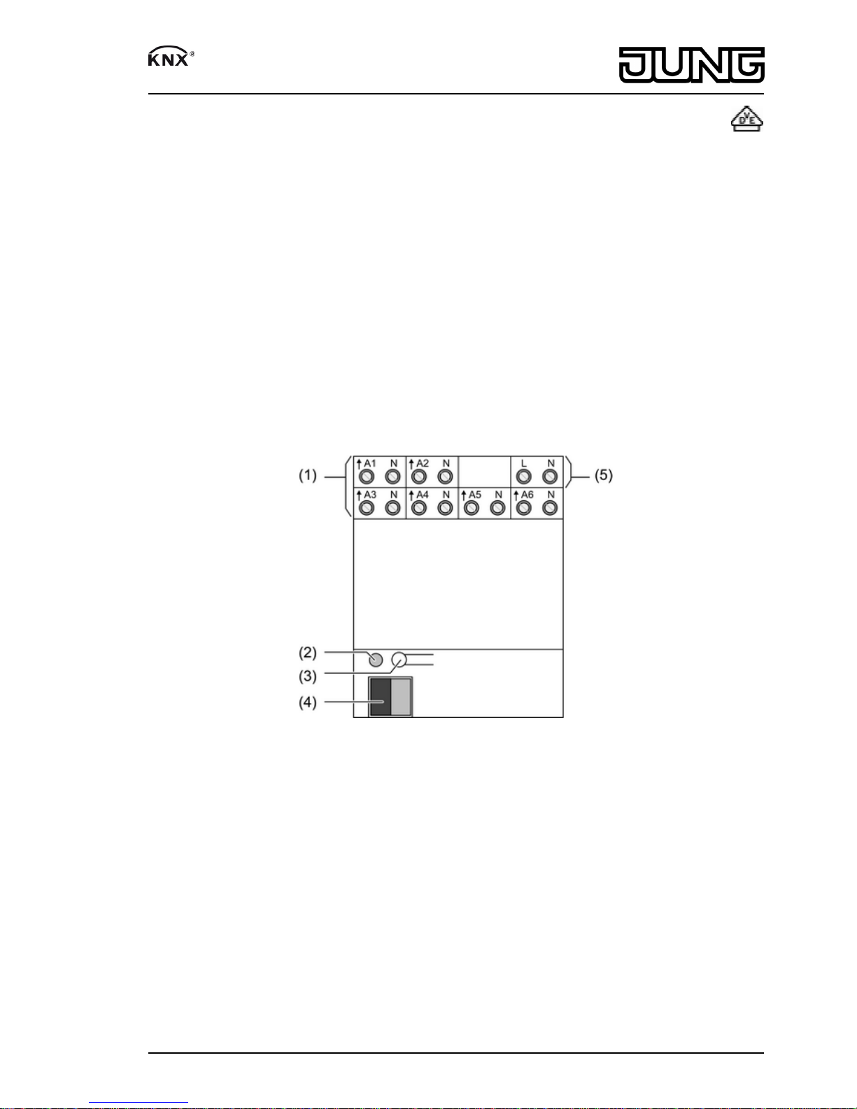
2 Device components
Figure 1
(1) Connection of electrothermal actuators
(2) Programming LED
(3) Programming button
(4) KNX connection
(5) Mains voltage connection
3 Function
System information
This device is a product of the KNX system and complies with the KNX directives. Detailed
technical knowledge obtained in KNX training courses is a prerequisite to proper
understanding.
The function of this device depends upon the software. Detailed information on loadable
software and attainable functionality as well as the software itself can be obtained from the
manufacturer´s product database. Planning, installation and commissioning of the device are
1/5
82543713
J:0082543713
20.12.2011
Page 2
carried out with the aid of KNX-certified software. The latest versions of product database and
the technical descriptions are available on our website.
Intended use
- Switching of electrothermal actuators for heaters or cooling ceilings
- Installation in distribution boxes on DIN rail according to DIN EN 60715
Product characteristics
- Switching operation or PWM operation
- Actuators with characteristics opened or closed without power
- Overload-protected, short circuit-protected
- Protection against jamming valves
- Forced position
- Various setpoints for forced position or emergency operation in case of bus failure for
summer or winter
- Cyclical monitoring of the input signals can be parameterized
- Feedback via bus, e.g. in case of mains failure, overload or sensor failure
i PWM operation: electrothermal actuators only have the positions "open" and "closed". In
PWM operation, switch-on and switch-off during the drive's cycle time achieves an almost
constant behaviour.
Overload protection
In order to protect the device and connected actuators, in case of overload the device
determines which output is involved and switches it off. Non-overloaded outputs continue to
work, which means that the rooms in question are still heated.
- In case of major overloads the actuator initially switches all off the outputs A1...A6 off.
- In the case of more minor overloads the actuators switches output groups A1...A3 and/or
A4...A6 off.
- The actuator determines the overloaded output in up to 4 test cycles.
- If in the event of only a minor overload it is not possible to unambiguously identify any
output as overloaded, then the actuator switches individual outputs off one after the other.
- The overload can be reported to the bus for each output.
4 Information for electrically skilled persons
4.1 Fitting and electrical connection
DANGER!
Electrical shock when live parts are touched.
Electrical shocks can be fatal.
Before carrying out work on the device or load, disengage all the
corresponding circuit breakers. Cover up live parts in the working environment.
Fitting the device
Observe the temperature range. Ensure adequate cooling.
o Mount device on DIN rail. Output terminals must be at the top.
2/5
82543713
J:0082543713
20.12.2011
Heating actuator 6-gang
Page 3

Connecting the device
Figure 2
Per output group A1...A3 and A4...A6 , connect only actuators of the same type.
Do not connect any mixed loads.
Connect actuators for frost-sensitive rooms to outputs A1 and A4 . These are switched off last
in the event of overload.
Do not exceed maximum number of actuators per output (see "Technical data").
Do not connect the neutral conductor from the output terminals through to additional devices.
Do not connect any inductive or capacitive loads.
o Connect the outputs according to connection diagram (figure 2).
o Connect the mains voltage (figure 2).
o Connect bus cable with connecting terminal.
Installing the cover
It is necessary to install a cover to protect the bus connection against hazardous voltages in the
connection area.
Figure 3: Installing the cover
o Route the bus cable towards the rear.
3/5
82543713
J:0082543713
20.12.2011
Heating actuator 6-gang
Page 4

o Install cover on top of the bus terminal so that it snaps into place (figure 3).
Removing the cover
Figure 4: Removing the cover
o Press the cover to the side and pull it off (figure 4).
4.2 Commissioning
Load the address and the application software
o Switch on the bus voltage
o Assign physical address.
o Load the application software into the device.
o Note the physical address on the device label.
5 Appendix
5.1 Technical data
Rated voltage AC 230 / 240 V ~
Mains frequency 50 / 60 Hz
Power loss approx. 2 W
Ambient conditions
Ambient temperature -5 ... +45 °C
Storage/transport temperature -25 ... +70 °C
Heating outputs
Contact type Semi-conductor (Triac), ε
Switching voltage AC 230 V / 240 V ~
Switching current 5 ... 50 mA
Switch-on current max. 1.5 A (2 sec)
Number of drives per output max. 4
Housing
Fitting width 72 mm / 4 modules
Connection of outputs
Connection mode Screw terminal
Single stranded 0.5 ... 4 mm²
finely stranded without conductor sleeve 0.5 ... 4 mm²
finely stranded with conductor sleeve 0.5 ... 2.5 mm²
KNX
KNX medium TP 1
Commissioning mode S-mode
Rated voltage KNX DC 21 ... 32 V SELV
4/5
82543713
J:0082543713
20.12.2011
Heating actuator 6-gang
Page 5

Power consumption KNX max. 125 mW
Connection type for bus Connection terminal
5.2 Troubleshooting
Actuators of an output or all outputs do not switch
Cause: An output is overloaded.
Determine cause of the overload switch-off. Eliminate short-circuits, replace defective
actuators. Check number of actuators connected to the output, reduce if necessary. Do not
exceed max. switching current.
Reset overload switch-off: disconnect device from mains completely for approx. 5 seconds,
switch off miniature circuit-breaker. Then switch on again.
i In case of overload, initially one or both output groups switch off for approx. 6 minutes.
After that the devices determines which output is overloaded and switches it off
permanently. This rest and test phase typically lasts 6...20 minutes.
i After resetting of the overload switch-off it is no longer possible for the device to determine
which output is overloaded. If the cause is not eliminated, overload switch-off will occur
again.
5.3 Accessories
Connection cover Art.-No.: 2050 K
5.4 Warranty
We reserve the right to make technical and formal changes to the product in the interest of
technical progress.
We provide a warranty as provided for by law.
Please send the unit postage-free with a description of the defect to our central customer
service office:
ALBRECHT JUNG GMBH & CO. KG
Service Center
Kupferstr. 17-19
D-44532 Lünen
Service-Line: +49 (0) 23 55 . 80 65 51
Telefax: +49 (0) 23 55 . 80 61 89
kundencenter@jung.de
ALBRECHT JUNG GMBH & CO. KG
Volmestraße 1
D-58579 Schalksmühle
Telefon: +49.23 55.8 06-0
Telefax: +49.23 55.8 06-1 89
E-mail: mail.info@jung.de
Internet: www.jung.de
www.jung-katalog.de
5/5
82543713
J:0082543713
20.12.2011
Heating actuator 6-gang
 Loading...