

Page 1
Binary input 8-gang, 24 V
Binary input 8-gang, 24 V
Art.-No.: 2128 REG
Operating instructions
1 Safety instructions
Electrical equipment may only be installed and fitted by electrically skilled persons.
Serious injuries, fire or property damage possible. Please read and follow manual fully.
Danger of electric shock. When connecting SELV/PELV systems, ensure safe isolation
from other voltages.
These instructions are an integral part of the product, and must remain with the end
customer.
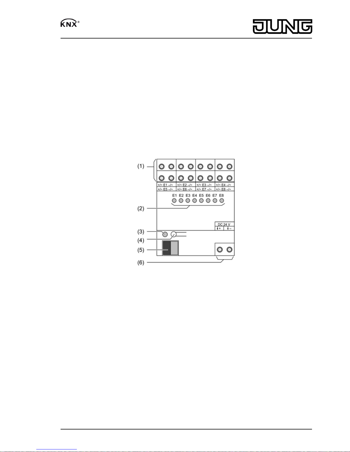
2 Device components
Figure 1: Binary input 8gang 24 V
(1) Connection for inputs
(2) Status LED inputs, yellow
On: voltage for signal level '1' present.
Off: voltage for signal level '0' present.
(3) Programming LED
(4) Programming key
(5) KNX connection
(6) Voltage output for potential-free contacts
3 Function
System information
This device is a product of the KNX system and complies with the KNX directives. Detailed
technical knowledge obtained in KNX training courses is a prerequisite to proper
understanding.
The function of this device depends upon the software. Detailed information on loadable
software and attainable functionality as well as the software itself can be obtained from the
manufacturer´s product database. Planning, installation and commissioning of the device are
carried out with the aid of KNX-certified software. The latest versions of product database and
the technical descriptions are available on our website.
1/6
82578403
J:0082578403
23.03.2012
Page 2

Intended use
- Polling of conventional switching or push-button contacts, glass break detectors etc. in
KNX systems, for reporting of states, operation of loads, etc.
- Mounting on DIN rail according to EN 60715 in distribution boxes
Product characteristics
- Status LED for each input
- Detection of voltage levels and changes on the input
- Transmitting the input state to the bus
- Transmission behaviour freely settable
- Functions: switching, dimming, blinds up/down, brightness values, temperatures, calling up
and saving scenes
- Inputs can be disabled separately
- External AC and DC voltages can be connected
- Auxiliary voltage output for polling potential-free contacts
- No separate power supply required.
- Separate reference potentials for inputs
4 Information for qualified electricians
4.1 Fitting and electrical connection
DANGER!
Electrical shock when live parts are touched.
Electrical shocks can be fatal.
Before carrying out work on the device or load, disengage all the
corresponding circuit breakers. Cover up live parts in the working environment.
Fitting the device
Observe the temperature range. Ensure adequate cooling.
o Mount device on DIN rail.
Connect 24 V binary input
Figure 2: Connection example – contacts supplied internally
2/6
82578403
J:0082578403
23.03.2012
Binary input 8-gang, 24 V
Page 3

Figure 3: Connection example – contacts supplied externally
(A.) 1 NO contact, internally supplied, DC
(B.) 1 NC contact, internally supplied, DC
(C.) NO contact, internally supplied, DC
(D.) NC contact, internally supplied, DC
(E.) NO contact, externally supplied, DC
(F.) NC contact, externally supplied, DC
(G.) NO contact, externally supplied, AC
(H.) NC contact, externally supplied, AC
For DC operation: observe polarity of the input voltage.
o Connect device as shown in the connection example.
i Use the output DC 24 V only for supplying its own inputs.
i If the output DC 24 V is used, no more than 4 switching events should take place
simultaneously on the supplied inputs. Otherwise the output could detect a fault and
generate an error message (see chapter 5.2. Troubleshooting).
Figure 4: Connection example – contacts supplied externally and internally
3/6
82578403
J:0082578403
23.03.2012
Binary input 8-gang, 24 V
Page 4

Connect SELV/PELV and FELV circuits together
Figure 5
FELV circuits do not have a safe separation for hazardous voltages. Therefore, they must be
insulated from safe extra low voltages SELV/PELV like mains circuits are.
o Leave two inputs unused (figure 5) between the inputs wired with SELV/PELV and FELV
circuits.
i Only use inputs supplied by auxiliary voltage DC 24 V for SELV/PELV circuits.
Installing the cover
It is necessary to install a cover to protect the bus connection against hazardous voltages in the
connection area.
Figure 6: Installing the cover
o Route the bus cable towards the rear.
o Install cover on top of the bus terminal so that it snaps into place (figure 6).
4/6
82578403
J:0082578403
23.03.2012
Binary input 8-gang, 24 V
Page 5

Removing the cover
Figure 7: Removing the cover
o Press the cover to the side and pull it off (figure 7).
4.2 Commissioning
Load the address and the application software
o Switch on the bus voltage
o Assign physical address.
o Load the application software into the device.
o Note the physical address on the device label.
5 Appendix
5.1 Technical data
KNX
KNX medium TP 1
Commissioning mode S-mode
Rated voltage KNX DC 21 ... 32 V SELV
Power consumption KNX max. 350 mW
Standby max. 200 mW
Connection type for bus Connection terminal
Ambient temperature -5 ... +45 °C
Storage/transport temperature -25 ... +70 °C
Inputs
Rated voltage AC/DC 12 ... 48 V
Signal level "0" signal AC/DC -48...+2 V
Signal level "1" signal AC/DC 8...48 V
Input voltage at nominal voltage 2 mA
Signal duration min. 30 ms
Rated frequency AC signal 30 ... 60 Hz
Number of contacts per input
NO contacts unlimited
NC contacts max. 20
Output DC 24 V
Output voltage DC 24 V SELV
Housing
Fitting width 72 mm / 4 modules
Power consumption
5/6
82578403
J:0082578403
23.03.2012
Binary input 8-gang, 24 V
Page 6

Standby max. 200 mW
Power loss max. 1 W
Connection
single stranded 0.2 ... 4 mm²
finely stranded without conductor sleeve 0.34 ... 4 mm²
finely stranded with conductor sleeve 0.14 ... 2.5 mm²
Cable length max. 100 m
5.2 Troubleshooting
All LEDs flash
Cause 1: Installation error, output voltage 24 V is short-circuited.
Eliminate short-circuit.
Cause 2: Installation error, the power supply voltage or another external voltage is connected at
the output DC 24 V.
Correct the connection, disconnect output terminal.
Cause 3: The output DC 24 V supplies more than 4 inputs that are impinged simultaneously
with the '1-'level during operation.
Correct connection. Use an additional external power supply if necessary.
5.3 Warranty
We reserve the right to make technical and formal changes to the product in the interest of
technical progress.
We provide a warranty as provided for by law.
Please send the unit postage-free with a description of the defect to our central customer
service office.
ALBRECHT JUNG GMBH & CO. KG
Volmestraße 1
58579 Schalksmühle
Telefon: +49.23 55.8 06-0
Telefax: +49.23 55.8 06-2 04
kundencenter@jung.de
www.jung.de
Service Center
Kupferstr. 17-19
44532 Lünen
Germany
6/6
82578403
J:0082578403
23.03.2012
Binary input 8-gang, 24 V
 Loading...