

Page 1
KNX Binary input
Ref.-nr.: 2114 REG, 2118 REG,
2126 REG
Operating Instructions
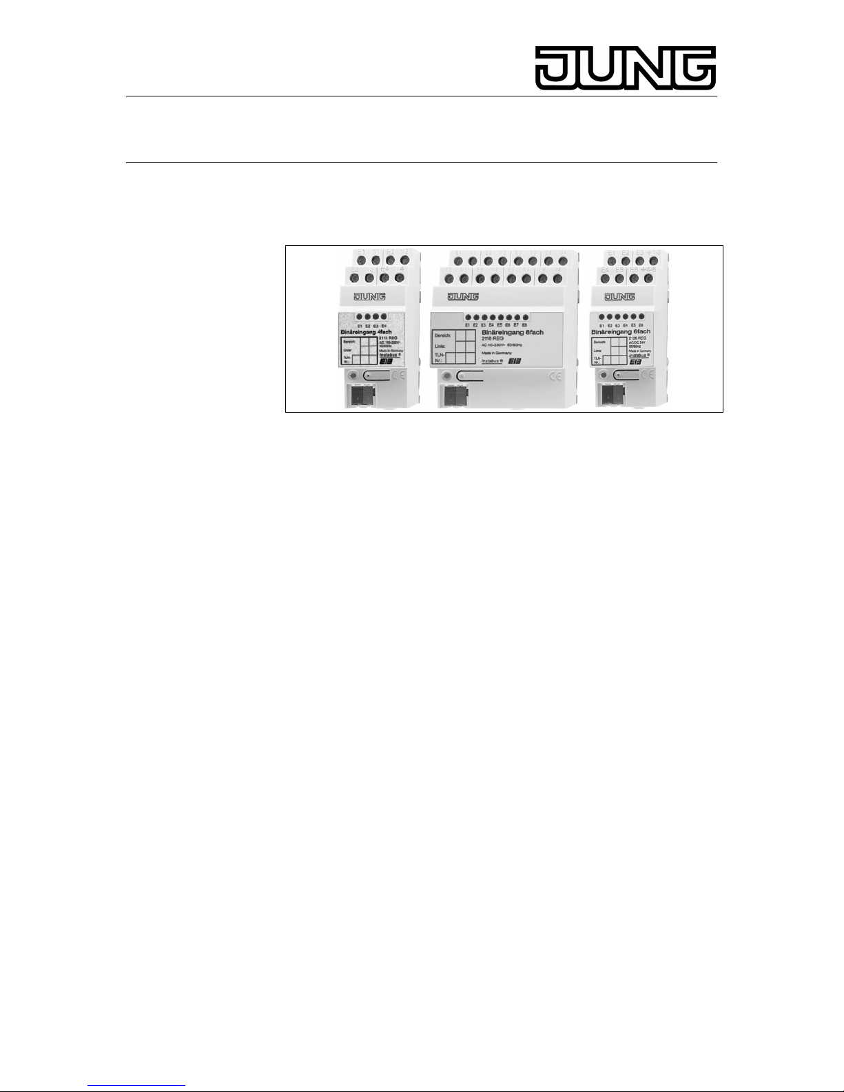
Binary input 4-, 6-, 8- channel
1. System information
This unit is a product of the instabus-EIB-System and corresponds to the
EIBA Guidelines. Detailed technical knowledge acquired in instabus
training courses is a prerequisite for the understanding of the system.
The functions of the device are software-dependent. Detailed information
on the software and the functions implemented and the software itself are
available from the manufacturer’s product data bank.
Planning, installation and commissionning of the device are effected with
the help of EIBA-certified software.
For the productdatabase and technical descriptions please refer to the
internet at www.jung.de offering up-to-date information..
2. Function
The binary inputs can detect the presence and the change of signal
voltages at their signal inputs.
Binary inputs can therefore be used to request the status of conventional
pushbuttons/switches, auxiliary contacts, door and window contacts and depending on programmed parameters - to transmit the switching status
as digital information to the instabus EIB.
The inputs can be used independent of each other. Each input is
equipped with an LED indicating the status of the contact connected.
Signal voltages can be applied to all inputs at the same time (100% duty
cycle).
The signal voltages of 24 V AC/DC or 230 V AC to be supervised must
be available externally.
3. Safety instructions
Attention: Electrical equipment must be installed and fitted by
qualified electricians only.
Non-observance of the installation instructions may cause fire or
other hazards.
Disconnect the mains voltage before connecting the inputs.
Stand: Mai-07 825 404 03
Page 2
KNX Binary input
Ref.-nr.: 2114 REG, 2118 REG,
2126 REG
4. Features
• Status indication for each input
• Different phases possible with the 230 V versions
• Separate reference potential for each input with 230 V versions
• Separate reference potentials (GND) for inputs 1 through 3 and 4
through 6 with the 24 V versions
• Supplementary software-independent debouncing circuits for the
inputs integrated
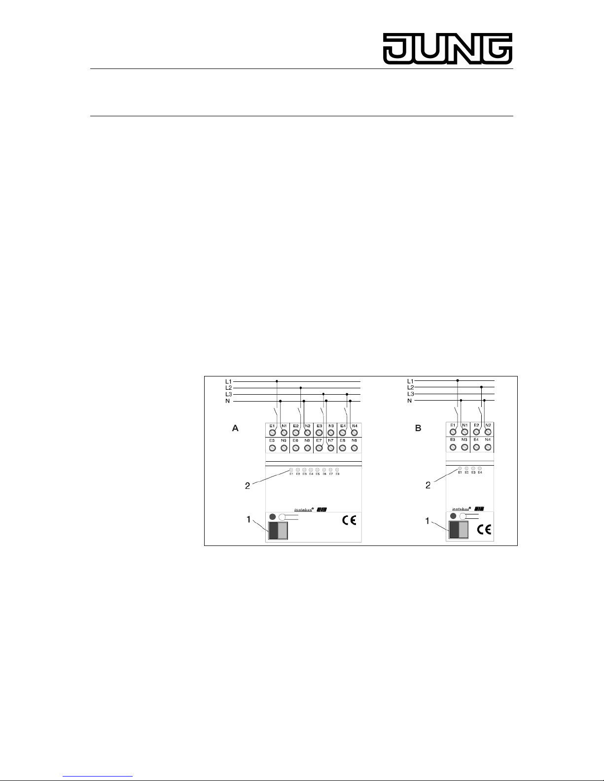
5. Connection
8-channel binary input 230 V (fig. A)
4-channel binary input 230 V (fig B)
The bus is connected via the bus connection terminal (1).
The contacts are connected as shown in fig. A or fig. B.
The reference potential N must be connected separately for each input.
The inputs (E1 through En) can be connected to different phase
conductors.
A signal at the input is indicated by the corresponding LED (2).
6-channel binary input 24 V (fig. C)
The bus is connected via the bus connection terminal (1). The cont acts
are connected as shown in fig. C.
Reference potential GND must be connected separately for inputs 1
through 3 and 4 through 6.
In DC operation, the (E1 through E6) are independent of polarity.
When a signal is present at one of the inputs, the corresponding LED (2)
is lit up.
L Important: For 24 V and 230 V voltages separate cables must be
used.
2
Page 3

KNX Binary input
Ref.-nr.: 2114 REG, 2118 REG,
2126 REG
6. Cap
Slide the cap with the bus wires at the bottom over the bus terminal (fig.
D) until it is heard to engage.
To remove the cap, push sideways and withdraw (fig. E).
The cap can be supplied as an extra part (Art. no. 2050 K).
7. Technical Data
General:
instabus EIB supply : 21 - 32 V DC
instabus EIB power consumption
4-channel binary input 230 V: max. 150 mW
8-channel binary input 230 V: max. 240 mW
6-channel binary input 24 V: max. 225 mW
Installation space requirements
4-channel binary input 230 V: 36 mm (2 module)
8-channel binary input 230 V: 72 mm (4 module)
6-channel binary input 24 V: 36 mm (2 module)
Ambient temperature : -5 °C ... +45 °C
Storage temperature : -25 °C ... +75 °C
3
Page 4

KNX Binary input
Ref.-nr.: 2114 REG, 2118 REG,
2126 REG
KNX
instabus EIB connection : instabus connecting terminal
Binary input connection : screw-type terminals
∅ for binary inputs 230 V : 0,75 to 4 mm² single-wire or
2 x 1,5 to 2,5 mm² single-wire
0,75 to 4 mm² stranded wire
without ferrule or
0,75 to 2,5 mm² stranded wire
with ferrule
∅ for binary inputs 24 V : 0,2 to 4 mm² single-wire or
2 x 0,2 to 2,5 mm² single-wire
0,75 to 4 mm² stranded wire
without ferrule or
0,5 to 2,5 mm² stranded wire
with ferrule
General specification of inputs:
Minimum signal duration
for pulse counting : 200 ms at 5 Hz signal clock
with mark-to-space ratio 1:1
Signal delay (software-independent)
rising edge : ca. 2 ms
falling edge : ca. 40 ms
Length of input line : max. 100 m (unshielded)
Universal binary input 4-channel 230 V / 8-channel 230 V:
Signaalspanning : 110 tot 230 V AC, 50 / 60 Hz
Ingangsstroom / kanaal : ca. 7 mA bij 230 V AC
Signaalniveau
‘0’-signaal : 0 tot 70 V AC
‘1’-signaal : 90 tot 253 V AC
Universal binary input 6-channel 24 V:
Signal voltage : 8 to 42 V AC/DC
Input current / channel : appr. 4 mA at 24 V AC/DC
Signal level
‘0’ signal : 0 to 1,8 V AC / -42 to +1,8 V DC
‘1’ signal : 8 to 42 V AC/DC
Technical specifications subject to change
4
Page 5

KNX Binary input
Ref.-nr.: 2114 REG, 2118 REG,
2126 REG
8. Guarantee
Our products are under guarantee within the scope of the statutory
provisions.
Please return the unit postage paid to our central service
department giving a brief description of the fault:
ALBRECHT JUNG GMBH & CO. KG
Service-Center
Kupferstr. 17-19
D-44532 Lünen
Service-Line: +(49) 23 55 . 80 65 51
Telefax: +(49) 23 55 . 80 61 65
E-Mail: mail.vka@jung.de
General equipment
Service-Line: +(49) 23 55 . 80 65 55
Telefax: +(49) 23 55 . 80 62 55
E-Mail: mail.vkm@jung.de
KNX equipment
Service-Line: +(49) 23 55 . 80 65 56
Telefax: +(49) 23 55 . 80 62 55
E-Mail: mail.vkm@jung.de
The
-Sign is a free trade sign addressed exclusively to the
authorities and does not include any warranty of any properties.
5
 Loading...