

Page 1

KNX Room actuator 230 V
Ref.-no.: RA 23024 REGHE
Operating instructions
Room actuator 230 V
Table of contents
1 Safety instructions 2
2 Device layout 2
3 Function 2
3.1 System Information 2
3.2 Designated use 3
4 Operation 4
4.1 Controls 4
4.2 Status indication 4
4.3 Modes of operation 4
4.4 Blind/shutter control priorities 5
5 Fitting and electrical connection 7
5.1 Installing the device 7
5.2 Connecting the device 8
5.3 Connecting switched loads 8
5.4 Connecting blind/shutter drives 8
5.5 Connecting 230 V valve drives 9
5.6 Attaching the bus terminal cap 9
6 Start-up 10
6.1 Measuring the blind/shutter and slat running times 10
6.2 Loading the physical address and the application software 10
7 Technical data 10
8 Help in case of trouble 12
9 Accessories 12
10 Guarantee 13
Page 2
KNX Room actuator 230 V
Ref.-no.: RA 23024 REGHE
1 Safety instructions
Electrical equipment must be installed and fitted by qualified
electricians only. Observe the current accident prevention regulations.
Failure to observe the instructions may cause damage to the device
and result in fire or other hazards.
The device is not suited for safe disconnection of the mains supply.
Do not connect consumers for SELV / PELV voltages..
Connect only electro-thermal valve drives to the heating outputs. Do
not connect inductive or capacitive loads.
Do not operate electro-thermal valve drives with DC voltage. Do not
connect three-phase AC motors.
These operating instructions are part of the product and must be left
with the final customer.
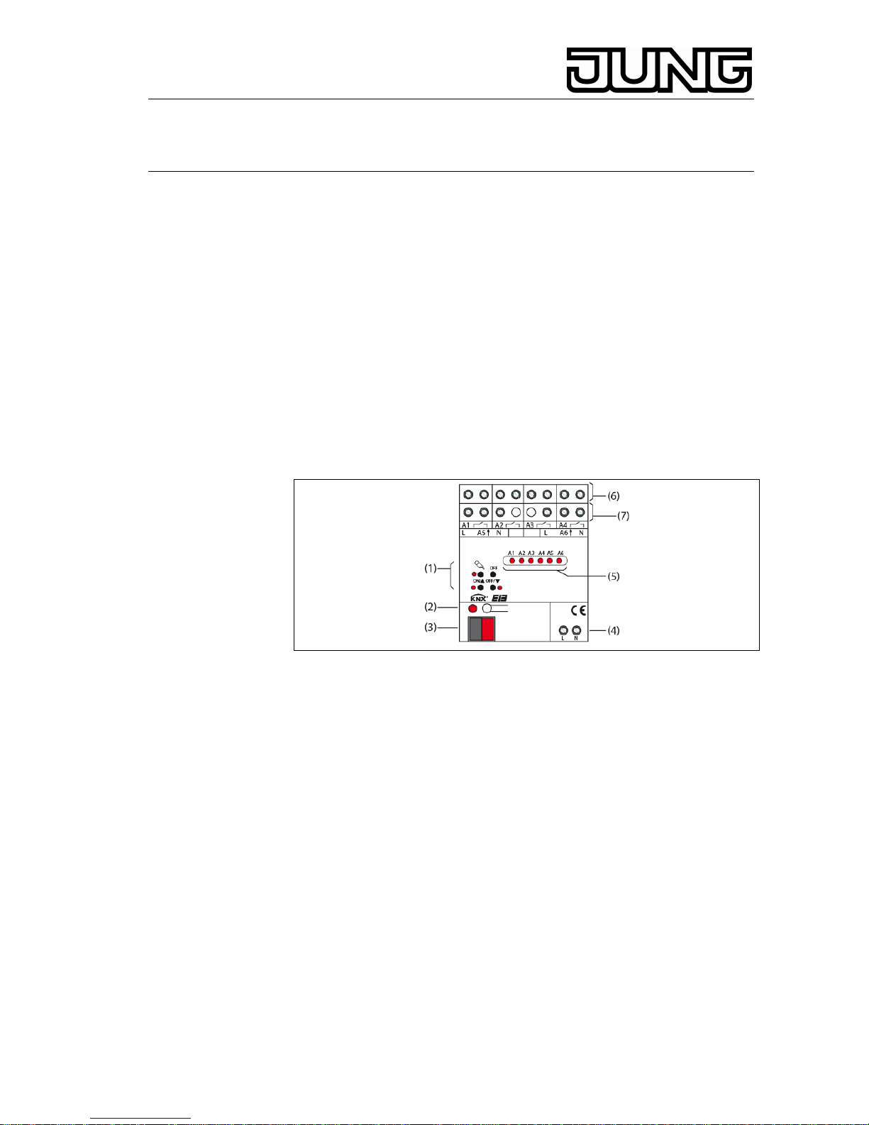
2 Device layout
Fig.1: Device layout of room actuator 230 V
(1) keypad for manual control
(2) programming button and LED
(3) KNX connection
(4) mains supply connection
(5) output status LEDs
(6) connecting terminals for consumers / blinds/shutters
(7) connecting terminals for 230 V valve drives
3 Function
3.1 System Information
This device is a product of the KNX system and complies with KNX
directives. Detailed technical knowledge obtained in KNX training courses is
a prerequisite to proper understanding.
The functionality of this device depends on the software.
Detailed information on loadable software and attainable functionality as
well as the software itself can be obtained from the manufacturer‘s product
database.
Planning, installation and commissioning of the unit is effected by means of
KNX-certified software. The full functionality is available with KNX
2
Page 3

KNX Room actuator 230 V
Ref.-no.: RA 23024 REGHE
3
commissioning software from version ETS3.0d onwards.
The product database, technical descriptions, conversion programs and
other utilities are available in their latest version on our Internet page.
3.2 Designated use
• Switching of electrical consumers AC 230 V with potential-free contacts
• Switching of electrically operated blinds, shutters, awnings and similar
curtains
• Heating outputs: electronic outputs for switching electro-thermal valve
drives
• - Installation on DIN rails in small distribution boards
Product features
• Manual output control, provisional operation
• Feedback in manual control mode and in bus operation
• Scene function
• Disabling of individual outputs by hand or via the bus
Switching function
• Make-contact and break-contact operation
• Logic operation and forcing function
• Feedback function
• Central switching function with group feedback
• Time functions: ON-delay, OFF-delay, staircase lighting timer with early-
warning function
Blind/shutter function
• Suitable for AC motors 230 V
• Direct control of blind/shutter position
• Direct control of slat position
• Checkback of running state, blind/shutter position and slat position
• Forced-control position from primary control
• Safety function: 3 independent wind alarms, rain alarm, frost alarm
• Sun protection function
Control of valve drives
• Switching or PWM operation
• Control of valve drives with working characteristics „normally open“ or
„normally closed“
• Overload and short-circuit protection
• Emergency operation in the event of bus failure for summer and winter
• Protection against jamming valves
• Forced-control position
• Cyclical monitoring of input signals parametrizable
L PWM operation: Electro-thermal valve drives only have an „open“ and a
„closed“ position. In PWM operation, these devices have quasicontinuous characteristics due to fast switching within the cycle time.
Page 4
KNX Room actuator 230 V
Ref.-no.: RA 23024 REGHE
4 Operation
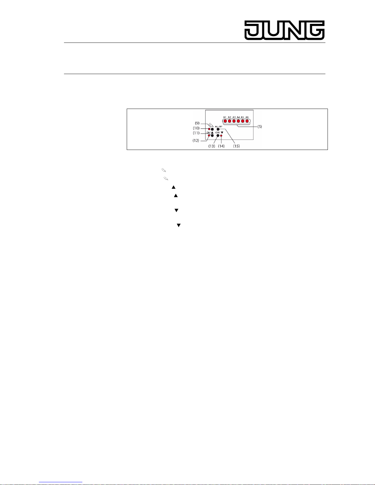
4.1 Controls
Fig.2: Controls – layout
(5) output status LEDs
(9) key : Manual control
(10) LED
: permanent manual control indicator
(11) key ON/ : switching on or opening a valve or raising a curtain / stop
(12) LED ON/ : lit up: switched on or blind/shutter moving upwards,
manual control mode
(13) key
OFF/ : switching off or closing a valve or lowering the
blind/shutter / stop
(14) LED
OFF/ : lit up: switched off or blind/shutter moving down,
manual control mode
(15) ALL OFF key: all outputs off, closing all valves and stopping all
drives
4.2 Status indication
The status LEDs A1...A6 (Fig. 2, 5) indicate the output states.
• Off: output is off
• On: output is on
• Flashing slowly: output in manual control mode
• Flashing fast: output disabled by permanent manual control mode
Heating outputs A5 and A6: The LED does not indicate the characteristics
of the valve drive, but the state of the output. ON = supplying current; OFF =
not supplying current.
In the PWM mode of operation, the LED indication cannot be interpreted as
representing the state of the valve drives connected and of the valves
controlled
4.3 Modes of operation
• Bus operation: operation via touch sensors or other bus devices
• Temporary manual control: manual operation locally with keypad,
automatic return to bus operation
• Permanent manual control mode: only manual operation locally on
device
L Bus operation in manual control mode disabled.
L Manual operation in the event of bus failure enabled.
L After failure and return of bus voltage, the device switches over to bus
operation.
4
Page 5

KNX Room actuator 230 V
Ref.-no.: RA 23024 REGHE
L After failure and return of mains voltage, the device switches over to bus
operation.
L Manual control mode can be disabled in operation via bus telegram.
4.4 Blind/shutter control priorities
• Highest priority: manual control
• 2nd priority: forced-control position
• 3rd priority: safety function
• 4th priority: sun protection
• Lowest priority: bus operation: raising / lowering, slat adjustment,
scenes, positioning
Activating the temporary manual control mode
Keypad operation must have been programmed beforehand
and not be disabled.
• Press the
key briefly, < 1 s,
LED A1 flashing, LED remains off.
L After 5 s without key-press, the actuator returns automatically to the bus
mode.
Deactivating the temporary manual control mode
The device must be in the temporary manual control mode.
• No key-press for 5 s.
- or -
• Press the
key briefly, < 1 s, several times until the desired output
status.
LEDs A1...A6 are no longer flashing, but indicating the output status.
Switching outputs: Depending on programming, the output relays switch
over to the position active at the time of deactivation of the manual
control mode, e.g. to forcing and logic operation.
Shutter outputs: Depending on programming, the blinds/shutters move to
the position active at the time of deactivation of the manual control
mode, e.g. forced-control position, safety or sun protection position.
Heating outputs: Depending on programming, the outputs switch over to
the position active at the time of deactivation of the manual control
mode, e.g. to forcing and logic operation.
Activating the permanent manual control mode
Keypad operation must have been programmed beforehand and not be
disabled.
• Press the
key for at least 5 s.
LED is on , LEDs A1 is flashing, the permanent manual control mode
is activated.
Deactivating the permanent manual control mode.
The device is in the permanent manual control mode.
• Press the
key for at least 5 s.
The
LED is off, bus operation is activated.
Switching outputs: Depending on programming, the output relays switch
5
Page 6

KNX Room actuator 230 V
Ref.-no.: RA 23024 REGHE
over to the position active at the time of deactivation of the manual
control mode, e.g. to forcing or logic operation.
Shutter outputs: Depending on programming, the blinds/shutters move to
the position active at the time of deactivation of the manual control
mode, e.g. forced-control, safety or sun protection
position.Zwangsstellung, Sicherheits-, Sonnenschutzposition.
Heating outputs: Depending on programming, the outputs switch over to
the position active at the time of deactivation of the manual control
mode, e.g. to forcing or logic operation.
Operating the outputs
The device must in the permanent or temporary manual control mode.
• Press the
key briefly, < 1 s, several times until the desired output is
selected.
The LED of the selected output A1...A6 flashes.
The ON/ und OFF/ LEDs indicate the status.
• Operate the output with the ON/
or OFF/ key.
Switching outputs: switching on or off.
Shutter outputs:
Brief press: blind/shutter stop
Long press: raising/lowering the blind/shutter
Heating outputs: opening or closing the valve
The selected output executes the respective commands.
The ON/
and OFF/ LEDs indicate the status.
L Heating outputs with PWM: After switching on with ON /▲ , the output is
regulated to the programmed fixed value. The LEDs only indicate the
state of the output, but not the state of the heating function.
L Temporary manual control: After all outputs have been selected one
after another, the device quits the manual control mode with the next
brief press.
Switching off all outputs
The device is in the permanent manual control mode.
Press the ALL OFF key.
All outputs will be switched off. All blinds/shutters will be stopped. All
heating valves will be closed.
Disabling individual outputs
The device is in the permanent manual control mode.
• Press the
key briefly, < 1 s, several times until the desired output is
selected.
The LED of the selected output A1...A6 flashes.
• Press the keys ON /▲ and OFF / ▼ simultaneously for at least 5 s. The
selected output is disabled.
All status LEDs of the selected output A1...A6 are flashing fast.
• Activate the bus mode (deactivate the permanent manual control mode).
L A disabled output can be operated in the manual control mode.
L If a disabled output is selected in the manual control mode, the LEDs are
6
Page 7

KNX Room actuator 230 V
Ref.-no.: RA 23024 REGHE
flashing twice briefly at intervals.
Re-enabling the outputs
The device must in the permanent manual control mode.
• Press the
key briefly, < 1 sseveral times until the desired output is
selected.
The status LEDs of the selected outputs A1...A6 flashes twice briefly at
intervals.
• Press the keys ON /▲ and OFF / ▼ simultaneously for at least 5 s.
The selected output A1...A6 is enabled.
The LED of the selected output A1...A6 is flashing slowly.
• Activate the bus mode (deactivate the permanent manual control mode).
Information for qualified electricians
Danger!
Electric shock in case of accidental contact with live parts. Electric
shocks can be fatal. Before working on the device, cut out the
mains supply and cover up live parts in the surroundings.
5 Fitting and electrical connection
5.1 Installing the device
• Snap the device onto a mounting rail as per EN 60715. The connecting
terminals must be at the top.
L The device warms up in operation. Observe the max. operating
temperature. Ensure sufficient cooling.
7
Page 8

KNX Room actuator 230 V
Ref.-no.: RA 23024 REGHE
5.2 Connecting the device
Fig.3: Connection
• Connect the bus line to the bus terminal.
• Connect the mains voltage supply.
• Connect the loads as described in the following chapters.
L Delivery state: provisional operation possible, output control via keypad
enabled, All outputs are configured as shutter outputs.
5.3 Connecting switched loads
Fig. 4: Connection of switched loads
The output must be parameterized as switching output.
• Connect the switched loads (Fig. 4). Do not exceed the permissible load
ratings (Technical data).
5.4 Connecting blind/shutter drives
For blind/shutter operation, two adjacent relay outputs are used as a
blind/shutter output. The left relay output A1, A3 is intended for the upward
direction and the right relay output A2, A4 for the downward direction.
8
Page 9

KNX Room actuator 230 V
Ref.-no.: RA 23024 REGHE
Fig. 5: Connection of blind/shutter motors
Observe the permissible load ratings (Technical data).
The output must have been parameterized as switching output.
Caution!
Risk of irreparable damage if several drives are connected in parallel
to one output.
Limit switch contacts can weld together and drives, blinds/shutters
and the shutter actuator can be irreparably damaged. Use an isolating
relay.
• Connect the drives (Fig 5).
5.5 Connecting 230 V valve drives
Fig. 6: Connection of electro-thermal
230 V valve drives
• Connect the valve drives (Fig. 6). Connect 4 valve drives maximum to
one output.
L Connect only electro-thermal valve drives.
L In the case of electro-thermal valve drives, attention must be paid to the
working characteristics normally open or normally closed (see project
design data).
5.6 Attaching the bus terminal cap
Connecting terminal for bus line to insert
Fig. 7: Protective cap
9
Page 10

KNX Room actuator 230 V
Ref.-no.: RA 23024 REGHE
10
To protect the bus line against dangerous voltages at the connecting
terminal, slide on the protective cap.
• Lead bus lines towards the rear of the device.
• Snap the cap onto the bus terminal (Fig. 7, A).
Removing the bus terminal cap
• Press the sides and pull out the cap (Fig. 7, B).
6 Start-up
6.1 Measuring the blind/shutter and slat running times
The blind/shutter running time is important for positioning
and scene moves. With Venetian blinds, the slat adjusting time is - for
technical reasons - part of the overall running time of blinds/shutters. The
opening angle of the slats is therefore defined as the running time required
between the ‚open‘ and ‚closed‘ positions.
The upward move is generally longer than the downward move and is
accounted for as running time prolongation in percent.
• Measure the UP and DOWN running times of the blind/shutter.
• Measure the slat adjusting time.
• Enter the measured values into the parameter settings list.
6.2 Loading the physical address and the application
software
• Switch on the bus voltage.
• Assign a physical address and download the application software (with
commissioning software).
• Switch on the mains voltage at the outputs.
Appendix
7 Technical data
KNX-medium TP1
Commissioning mode S-mode
KNX supply 21...32 V DC
KNX power consumption max. 150 mW
Rated voltage AC 230 / 240 V~
Mains frequency 50/60 Hz
Heat dissipation max. 6 W
Ambient temperature -5 °C...+45 °C
Storage temperature -25 °C...+70 °C
Fitting width 72 mm (4 TE)
Weight approx. 290 g
Connection
KNX connecting terminal
230 V supply and outputs screw terminals
Page 11

KNX Room actuator 230 V
Ref.-no.: RA 23024 REGHE
11
Connecting cross-section
Single-wire 0.5...4 mm²
stranded wire without ferrule 0.35...4 mm²
stranded wire with ferrule 0.14...2.5 mm²
Heating outputs
Contact type semiconductor, ε
Switching voltage AC 230/240 V
Switching current 5 mA … 50 mA
Inrush current max. 1.5 A, 2 s
Number of drives per output max. 4
Relay outputs
Contact type potential-free n.o. contact
(μ-contact)
Switching voltage AC 230/240 V
Switching capacity AC1 (cos ϕ > 0.8) 16 A
Switching capacity AC3 (cos ϕ < 0.8) 6 A
Switching capacity AX (fluorescent lamps) 16 AX
Max. inrush current 200 μs 800 A
Max. inrush current 20 ms 165 A
Load rating of relay outputs
Resistive load 3000 W
Capacitive load: (max. 140 μF) 16 A
Motors 1380 VA
Lamp loads
Incandescent lamps: 3000 W
230 V halogen lamps 2500 W
TRONIC transformers 1500 W
Inductive transformers: 1200 VA
Fluorescent lamps
non-compensated 1000 W
parallel compensated (max. 140 μF) 1160 W
lead-lag circuit (max. 140 μF) 2300 W
Compact fluorescent lamps
non-compensated 1000 W
parallel compensated (max. 140 μF) 1160 W
Mercury vapour lamps
non-compensated 1000 W
parallel compensated (max. 140 μF)
Electronic Ballasts see product
documentation
Technical specifications subject to change.
Page 12

KNX Room actuator 230 V
Ref.-no.: RA 23024 REGHE
12
8 Help in case of trouble
Manual control with keypad not possible
Manual operation not parameterized.
Parameterize manual operation.
Manual operation disabled via the bus.
Enable the manual control mode.
No mains voltage.
Switch on the mains voltage.
Check the fuses.
Output control not possible
Output disabled.
Cancel the state of disabling.
None of the outputs operational
All outputs are disabled.
Cancel the state of disabling.
Permanent manual control mode active.
Deactivate the permanent manual control mode (switch this mode off).
Application software stopped, programming LED flashes.
Make a reset: Disconnect the device from the bus,
reconnect after ca. 5 s.
Operation via the bus impossible
No bus voltage.
Switch on the bus voltage; have the installation
checked by a qualified electrician.
Application software stopped, programming LED flashes.
Make a reset: Disconnect the device from
the bus, reconnect after ca. 5 s..
9 Accessories
Protective cap Ref.-no.: 2050 K
Isolating relay AP Ref.-no.: TR-S
Isolating relay UP Ref.-no.: TR-S REG
Isolating relay UP Ref.-no.: TR-S UP
Thermal valve drive 230 V Ref.-no.: TVA 110 WW
Page 13

KNX Room actuator 230 V
Ref.-no.: RA 23024 REGHE
10 Guarantee
Our products are under guarantee within the scope of the statutory
provisions.
Please return the unit postage paid to our central service department
giving a brief description of the fault:
ALBRECHT JUNG GMBH & CO. KG
Service Center
Kupferstr. 17-19
D-44532 Lünen
Service-Line: +49 (0) 23 55 . 80 65 51
Telefax: +49 (0) 23 55 . 80 61 89
mail.vki@jung.de
General equipment
Service-Line: +49 (0) 23 55 . 80 65 55
Telefax: +49 (0) 23 55 . 80 62 55
mail.vkm@jung.de
KNX equipment
Service-Line: +49 (0) 23 55 . 80 65 56
Telefax: +49 (0) 23 55 . 80 62 55
mail.vkm@jung.de
The -Sign is a free trade sign addressed exclusively to the authorities and
does not include any warranty of any properties
13
 Loading...