

Page 1
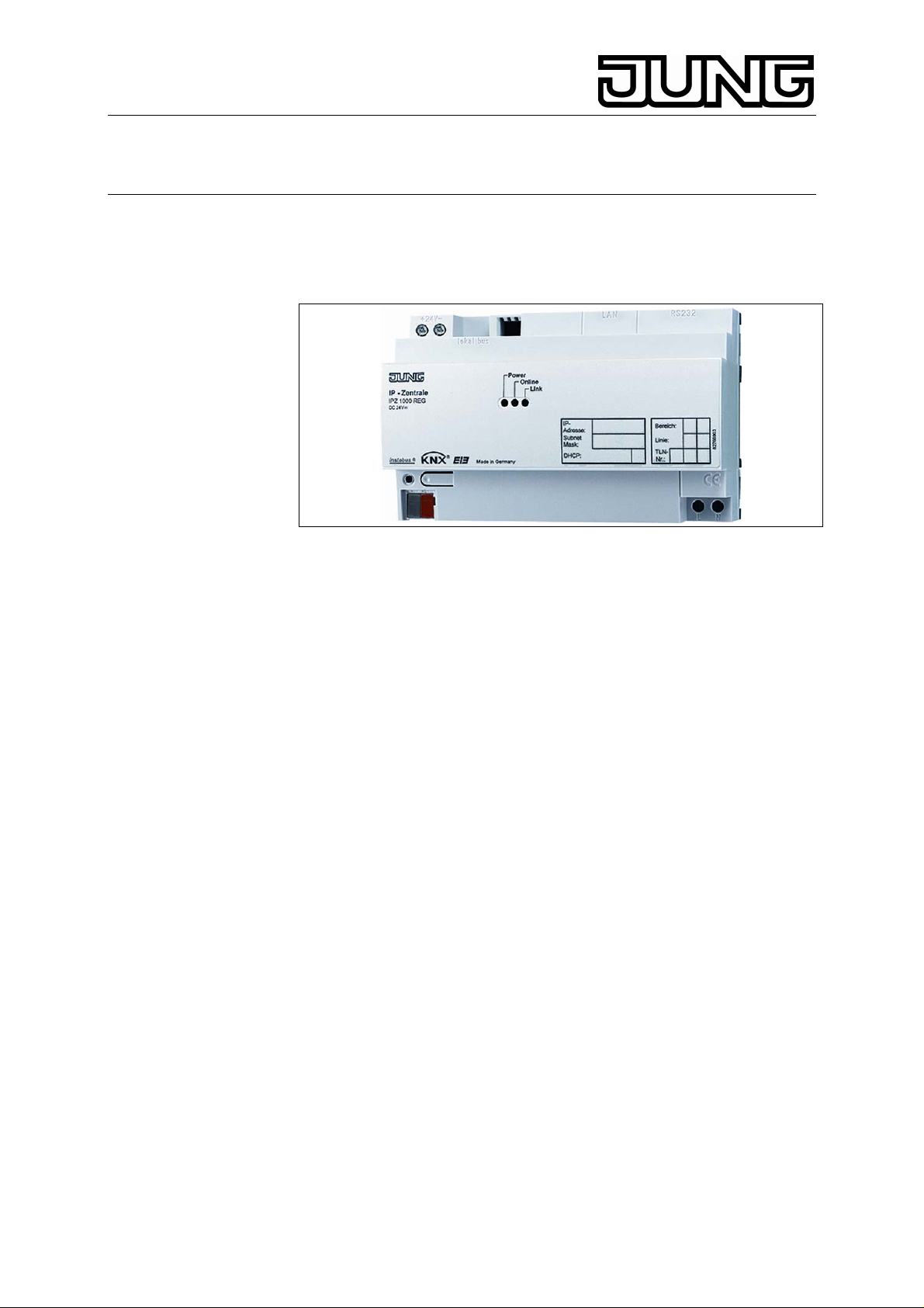
KNX IP Central Unit
Ref.-no.: IPZ 1000 REG
Operating Instructions
IP Central Unit
1. System information
This device is a product of the instabus EIB system and complies with
EIBA directives. Detailed technical knowledge obtained in instabus
training courses is a prerequisite to proper understanding. The
functionality of this device depends on the software. Detailed information
on loadable software and attainable functionality as well as the software
itself can be obtained from the manufacturer’s product database.
Planning, installation and commissioning of the unit is done by means of
EIBA-certified software. The latest version of the product database and of
the technical descriptions are always available in the Internet under
www.jung.de
2. Safety warnings
Attention
Electrical equipment must be installed and fitted by qualified
electricians only and in strict observance of the relevant accident
prevention regulations. Failure to observe any of the installation
instructions may cause fire and other hazards
Important: The present installation instructions are to give a first
overview of the use and information on the connection of the IP central
unit. A detailed description of the product and configuration of the
necessary devices can be found in the respective EIB product
documentation.
Stand: Aug-07 325 491 03
3. Function
The IP central unit is the interface between the Ethernet LAN (Local Area
Network) and the instabus EIB, and in future also the e2i system. With an
Ethernet connection, the user has access from the local PC of his LAN or
also via the Internet to his instabus EIB or to his e2i system. The Internet
connection can be established via DSL, LAN (RJ45-port) or also with a
V90 modem / ISDN-adapter (RS232 port). The IP central unit acts as a
server and can be comfortably operated as a central control, reporting
Page 2
KNX IP Central Unit
Ref.-no.: IPZ 1000 REG
and checking unit with the web browser of a PCs (Microsoft
Explorer from V 5.5 onwards) or other suitable LAN devices as, for
instance, a PDA.
© Internet
4. Characteristics
User-controlled commissioning and configuration assistant, system clock
functions, central year timer switch with astro function and day profiles,
presence simulation, logic functions, event reporting function via e-mail,
integrated e-mail address book, central functions, lightscenes, scenes for
HVAC and alarm system applications, etc.
4.1. Directory server
Data exchange with the IP central unit via the Internet requires the use of
a directory server. A directory server is a server which can be reached via
Internet and which is the interface between a PC and the IP central unit.
When accessed from the web browser, a web page of the directory
server opening up a portal is first called up. The directory server checks
the connection or establishes the connection with the IP central unit.
When the connection has been established, access via the open portal to
the IP central unit is possible after verification of the access data.
5. Modes of operation
Depending on the existing system equipment, the IP central unit can be
operated in different modes.
• operation in an LAN
• operation in an LAN via a dedicated phone line to the Internet
• operation in an LAN with dial-in connection to the Internet and
triggering via modem (analog or ISDN)
• operation in an LAN with triggering or a-b port behind a telephone
system
• operation in a telephone system with dial-in to the Internet via
modem (analog or ISDN)
The Connection required in each case is shown in the pictures below.
2
Page 3
KNX IP Central Unit
Ref.-no.: IPZ 1000 REG
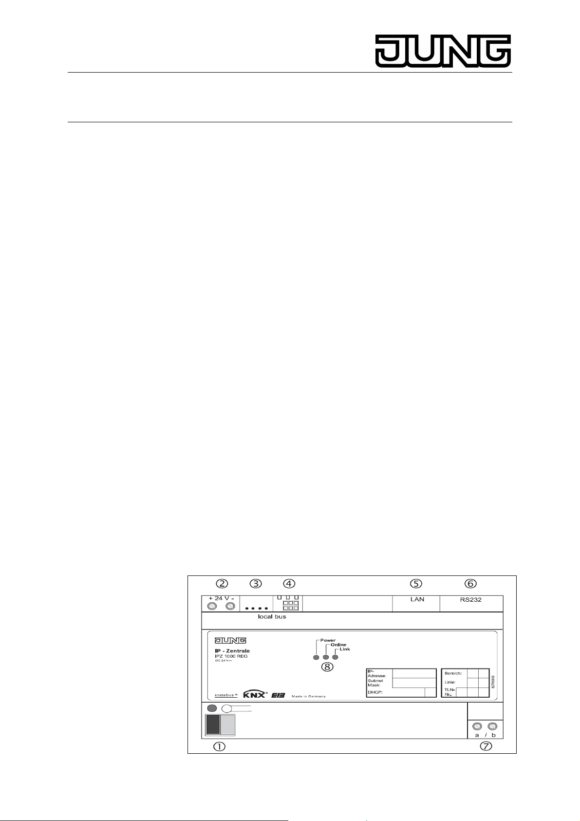
Designation and function of the connecting ports
(1) bus connection terminal for EIB connection
(2) screw terminals for polarity-independent 24 V DC connection, e.g.
from the unchoked output of the EIB power supply unit
(3), (4) e2i system contacts for future e2i applications (presently not
supported)
(5) RJ45 socket for LAN connection
(6) 9-pole SUB-D plug for V90 modem or ISDN adapter
(7) screw terminals for a-b trigger input
(8) 3 LEDs:
power (green) => lit up after initialization and presence of 24 V supply
voltage
online (yellow) => signals active connection via the RS232 interface
link (yellow) => lit up when connection to LAN (Ethernet connection
point, ECP) is established, flickers during data transmission via LAN
port
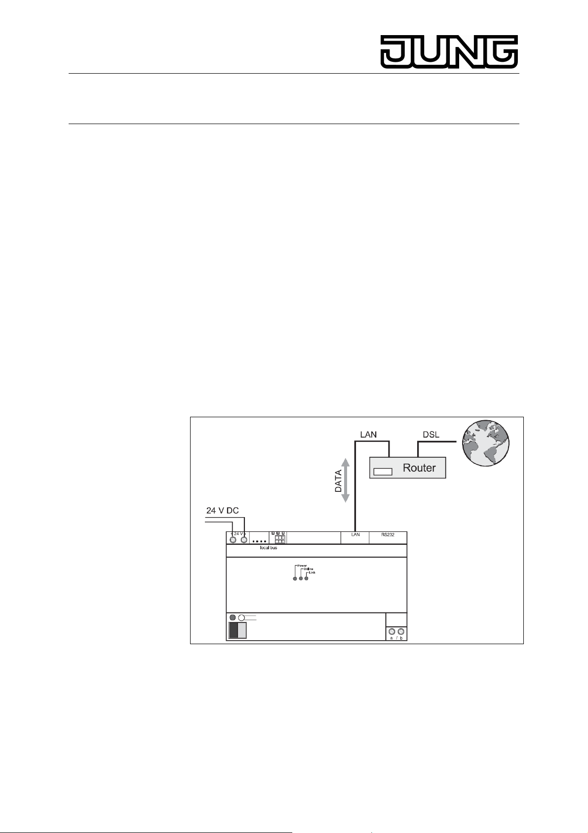
5.1. Operation in LAN
Access to the IP central unit is via a local Ethernet (LAN) from a local PC.
Operation in LAN with dedicated phone line
A local Ethernet (LAN) establishes – e.g. by means of a router – a
permanent connection with the Internet. This is useful in the event of a
flat-rate tariff. With „keep-alive“ telegrams, the IP central unit ensures that
the router does not disconnect the link. After a forced disconnection by
the service provider, the directory server is informed about the new IP
address when the link is reestablished. Access from outside is by means
of an external PC and its brower interface after passwort entry via a safe
Internet connection. After successful log-in, the web page of the IP
central unit appears. The EIB system can then be monitored and
operated directly.
3
Page 4

KNX IP Central Unit
Ref.-no.: IPZ 1000 REG
Operation in LAN with dial-in, triggering via modem
A local Ethernet (LAN) establishes – e.g. by means of a router – a
connection with the Internet on request. This type of connection is useful
with a time/volume tariff. In the event of an access from outside, e.g. via
external PC, the user interface of the browser initiates a trigger request
by the directory server to a specific phone number. The trigger request
from the directory server via modem/ISDN adapter causes the IP central
unit to establish a safe connection to the Internet via LAN and router. As
soon as the connection is established, the IP central unit logs in with the
directorty server.
Operation in LAN, triggering via a-b port behind telephone system
4
Page 5

KNX IP Central Unit
Ref.-no.: IPZ 1000 REG
A local Ethernet (LAN) establishes – e.g. by means of a router – a
connection with the Internet on request. This type of connection is useful
with a time/volume tariff. In the event of an access from outside, e.g. via
external PC, the user interface of the browser initiates a trigger request
by the directory server to a specific phone number. The trigger request
from the directory server via the a-b input of the IP central unit causes the
IP central unit to establish a safe connection to the Internet via LAN and
router. As soon as the connection is established, the IP central unit logs
in with the directory server.
Important: The request from the directory server to the a-b port does not
establish a telephone connection so that there are no connection
charges. The IP central unit detects the „ringing“ signal at the a-b
terminals. The calling number is not identified (CLI). For this reason, each
call on the connected line will be detected as a trigger signal. IIf this is
undesired, a separate MSN can be assigned to the telephone system in
an ISDN structure. In an analog structure, a separate connection is
necessary in this case.
5.2. Operation in a telephone system
Dial-in into the Internet via the LAN is not possible. The LAN interface
thus only offers access via PC, PDA, etc. for browser use. If the IP
central unit is to accessed from outside, the directory server must send a
trigger signal together with caller identification (CLI) to a specific phone
number via the connected modem/ISDN adapter (CLIP function
required). The IP central unit identifies the directory server by th
transmitted phone number, there is no call set-up. The IP central unit
dials in with a service provider via modem/ISDN adapter. As soon as a
safe connection with the Internet is established, the IP central unit logs in
with the directory server.
Important: After dial-in of the IP central unit into the Internet, telephone
charges depending on the specific online tariff will become due.
5
Page 6

KNX IP Central Unit
Ref.-no.: IPZ 1000 REG
6. Cap
Slide the cap with the bus wires at the bottom over the bus terminal (fig.
A) until it is heard to engage.
To remove the cap, push sideways and withdraw (fig. B).
The cap is available as an accesory (Art. No. 2050 K)
7. Technische Daten
Supply : 21 – 32 V DC, (e.g. via
unchoked EIB voltage output)
Power consumption : ca. 3 W without e2i
ca. 6 W with e2i
Connections
24 V supply : screw terminals
and a-b trigger input 0.5 –4 mm
0.34 – 4 mm
without ferrule or
0.14– 2.5 mm2 stranded wire with
ferrule
instabus EIB : instabus connecting terminal
Ethernet / LAN : RJ45 socket
(10/100 MBit/s Fast Ethernet)
Serial RS232 : SUB-D plug, 9-pole
e2i (presently not supported)
external : e2i plug, 4-pole
internal : e2i strip connector, 6-pole
Ambient temperature : -5 °C … +45 °C
Storage temperature : -25 °C … +70 °C
Installation width : 144 mm (8 modules)
Technical specifications subject to change
2 single wire or
2 stranded wire
6
Page 7

KNX IP Central Unit
Ref.-no.: IPZ 1000 REG
8. Guarantee
Our products are under guarantee within the scope of the statutory
provisions.
Please return the unit postage paid to our central service
department giving a brief description of the fault:
ALBRECHT JUNG GMBH & CO. KG
Service-Center
Kupferstr. 17-19
D-44532 Lünen
Service-Line: +(49) 23 55 . 80 65 51
Telefax: +(49) 23 55 . 80 61 65
E-Mail: mail.vka@jung.de
General equipment
Service-Line: +(49) 23 55 . 80 65 55
Telefax: +(49) 23 55 . 80 62 55
E-Mail: mail.vkm@jung.de
KNX equipment
Service-Line: +(49) 23 55 . 80 65 56
Telefax: +(49) 23 55 . 80 62 55
E-Mail: mail.vkm@jung.de
The
authorities and does not include any warranty of any properties.
-Sign is a free trade sign addressed exclusively to the
7
 Loading...