

Page 1

Bedienungsanleitung
Schaltaktor 4-fach
Art. Nr. 2134.16 REG
Schaltaktor 4-fach C-Last
Art. Nr. 2134.16 C REG
Schaltaktor 6-fach
Art. Nr. 2136.6 REG
Schaltaktor 8-fach
Art. Nr. 2138.10 REG
Schaltaktor 8-fach C-Last
Art. Nr. 2138.16 C REG
325 064 13 06.03
J:0082506413
D
GB NL
F N E
Page 2
D
Dieses Gerät ist ein Produkt des instabus-EIB-Systems und entspricht den EIBA-Richtlinien. Detaillierte Fachkenntnisse durch
instabus-Schulungen werden zum Verständnis vorausgesetzt.
Die Funktion des Gerätes ist softwareabhängig. Detaillierte Informationen, welche Software geladen werden kann und welcher
Funktionsumfang sich damit ergibt sowie die Software selbst,
sind der Produktdatenbank des Herstellers zu entnehmen.
Planung, Installation und Inbetriebnahme des Gerätes erfolgen
mit Hilfe einer von der EIBA zertifizierten Software.
Die Produktdatenbank und die technischen Beschreibungen finden
Sie stets aktuell im Internet unter www.jung.de.
Systeminformation
Gefahrenhinweise
Gefahrenhinweise
Achtung! Einbau und Montage elektrischer Geräte dürfen
nur durch eine Elektrofachkraft erf olgen. Dabei sind die geltenden Unfallverhütungsvorschriften zu beachten.
Zur Vermeidung eines elektrischen Schlages, vor Arbeiten am
Gerät freischalten (Sicherungsautomat abschalten).
Bei Nichtbeachtung der Installationshinweise können Schäden am Gerät, Brand oder andere Gefahren entstehen.
Bei Auslieferung ist der Schaltzustand der Ausgänge nic ht
definiert.
D
Page 3
D
Die Schaltaktoren 4-fach, 4fach C-Last, 6-fach, 8-f ach und 8fach CLast schalten mit ihren potenzialfreien Kontakten elektrische Verbraucher über den instabus EIB.
Schaltbefehle erfolgen durch Betätigung v on Tastsensoren oder Binäreingängen des instabus EIB-Systems.
Die Schaltaktoren 4fach, 4fach C-Last, 8fach und 8fach C-Last
(Ausgänge A1 - A4) verfügen über Schaltstellungsanzeigen. Sie
dienen gleichzeitig der manuellen Betätigung der Relais unabhängig vom instabus EIB.
Die Schaltkontakte der C-Last Schaltaktoren sind speziell für Lasten
mit kapazitivem Charakter und dadurch bedingten hohen Einschaltströmen ausgelegt (siehe technische Daten).
Die Geräte benötigen keine zusätzliche Stromversorgung.
Funktion
Hinweise
• Die maximale Schaltleistung der Ausgänge A1 - A4 und A5 - A8 des
Schaltaktor 8-fach sind unterschiedlich. Beachten Sie die Angaben in den technischen Daten.
• Die Relaisausgänge eines Aktors schalten bei Ansteuerung über
ein Zentraltelegramm mit geringer zeitlicher Verzögerung.
• Keine Drehstrommotoren anschließen.
• Die manuelle Betätigung der Relais ist busunabhängig und wird
nicht in die Schaltobjekte übernommen. Dadurch kann ein per
Software gesperrter Ausgang dennoch per Hand geschaltet werden.
• Eine Belegung von 230 V und SELV an verschiedenen Ausgängen eines Aktors ist nicht zulässig.
D
Page 4
D
A B
Anschluss
Anschluss
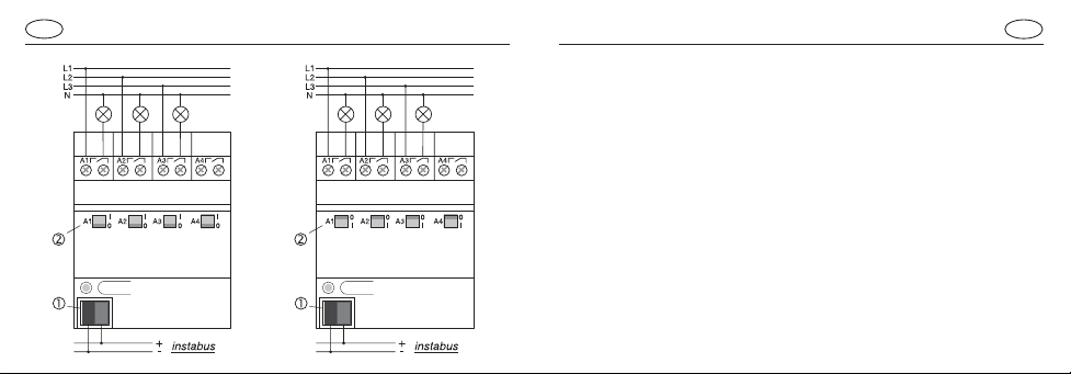
D
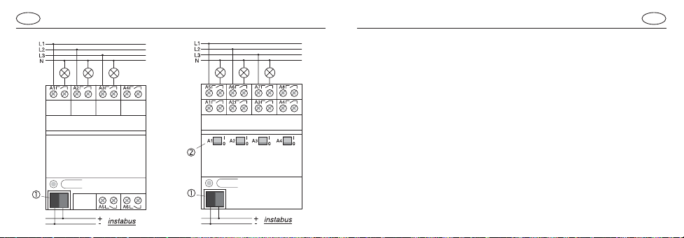
Schaltaktor 4fach (Bild A), Schaltaktor 4fach C-Last (Bild B).
Der Busanschluss erfolgt mit der Busanschlussklemme .
Die Schaltzustände der Relais werden durch die Schaltstellungs-
anzeigen angegeben. Sie dienen gleichzeitig der manuellen Betätigung der Relais unabhängig vom EIB.
Hinweis: Beachten Sie, dass die Schaltstellungsanzeigen beim
C-Last Aktor (im Bild rechts) konstruktionsbedingt invertiert sind.
Der Anschluss erfolgt gemäß Schaltbild.
Es können verschiedene Außenleiter an den Geräten angeschlos-
sen werden.
Page 5
D
C D
Anschluss
Anschluss
D
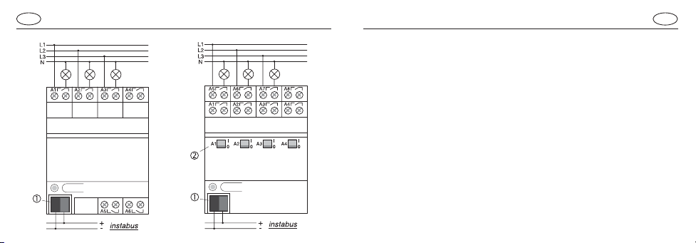
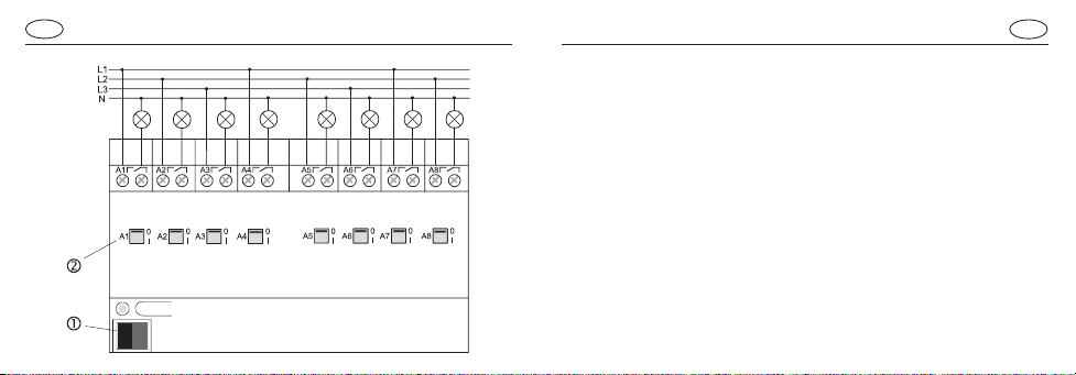
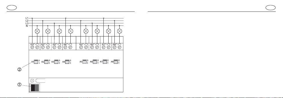
Schaltaktor 6fach (Bild C), Schaltaktor 8fach (Bild D).
Der Busanschluss erfolgt mit der Busanschlussklemme .
Beim Schaltaktor 8fach werden die Schaltzustände der Relais für die
Ausgänge A1 - A4 durch die Schaltstellungsanzeigen angegeben.
Sie dienen gleichzeitig der manuellen Betätigung der Relais für die
Ausgänge A1 - A4 des Schaltaktor 8fach unabhängig vom EIB .
Der Anschluss erfolgt gemäß Schaltbild.
Es können verschiedene Außenleiter an den Geräten angeschlos-
sen werden.
Page 6
D
E
Anschluss
Anschluss
Schaltaktor 8fach C-Last (Bild E).
D
Der Busanschluss erfolgt mit der Busanschlussklemme .
Beim Schaltaktor 8fach werden die Schaltzustände der Relais
durch die Schaltstellungsanzeigen angegeben. Sie dienen gleichzeitig der manuellen Betätigung der Relais unabhängig vom EIB.
Hinweis: Beachten Sie, dass die Schaltstellungsanzeigen beim
C-Last Aktor konstruktionsbedingt invertiert sind.
Der Anschluss erfolgt gemäß Schaltbild.
Es können verschiedene Außenleiter an den Geräten angeschlos-
sen werden.
Page 7

D
F
G
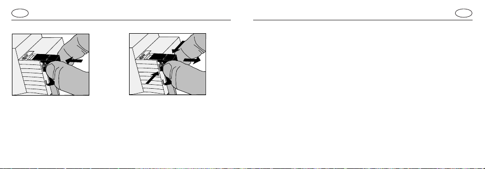
Abdeckkappe
Die Abdeckkappe mit nach unten herausgeführten Busleitungen
über die Busklemme schieben (Abb. F) bis sie spürbar einrastet.
Entfernen Sie die Abdeckkappe durch seitliches Drücken
und Abziehen (Abb. G).
Die Abdeckkappe ist als Zubehör (Art. Nr. 2050 K) lieferbar.
Technische Daten
Allgemeines
Versorgung instabus EIB : 21 - 32 V DC
Leistungsaufnahme instabus EIB : typ. 150 mW
Anschluss instabus EIB : instabus Anschlussklemme
Anschluss Netz : Schraubklemmen
1,5 – 4 mm² eindrähtig oder
2 x 1,5 – 2,5 mm² eindrähtig
0,75 – 4 mm² feindrähtig
ohne Aderendhülse oder
0,5 – 2,5 mm² feindrähtig
mit Aderendhülse
D
Page 8

D
Allgemeines
Kontaktart Ausgänge : potenzialfreie Schließer
(µ-Kontakt)
Umgebungstemperatur : -5 °C bis +45 °C
Lagertemperatur : -25 °C bis +70 °C
Einbaubreite
nur Schaltaktor 8fach C-Last : 144 mm (8 TE)
alle anderen Aktoren : 72 mm (4 TE)
Technische DatenTechnische Daten
Ausgänge Schaltaktor 4fach und 8fach (Ausgänge A1 – A4)
Schaltspannung : 230 V AC, 400 V AC
Schaltvermögen 230 V AC : 16 A / AC1; 10 A / AC3
Schaltvermögen 400 V AC : 10 A / AC1; 6 A / AC3
Schaltleistung
Glühlampen : 2500 W
Leuchtstofflampen
unkompensiert : 2500 W
parallelkompensiert : 1300 W / 140 µF
Duo-Schaltung : 2 x 2500 W
HV-Halogenlampen: : 2500 W
NV-Halogenlampen: : 500 VA
Tronic Trafos : 1300 VA
D
Page 9

D
Ausgänge Schaltaktor 6fach und 8fach (Ausgänge A5 – A8)
Schaltspannung : 230 V AC
Schaltvermögen 230 V AC : 6 A / AC1
Schaltleistung
Glühlampen : 1000 W
Leuchtstofflampen
unkompensiert, cos ϕ = 0,5 : 500 W
parallelkomp., cos ϕ = 1 : 2 x 58 W / 14 µF
3 x 36 W / 14 µF
6 x 18 W / 14 µF
Duo-Schaltung, cos ϕ = 1 : 1000 W
Siemens EVG
58 W Leuchtstofflampe : 10 Stk.
36 W Leuchtstofflampe : 15 Stk.
18 W Leuchtstofflampe : 15 Stk.
Technische DatenTechnische Daten
Ausgänge Schaltaktor 4fach C-Last und 8fach C-Last
Schaltspannung : 230 V AC, 400 V AC
Schaltvermögen 230 V AC : 16 A / AC1; 10 A / AC3
Schaltvermögen 400 V AC : 10 A / AC1; 6 A / AC3
Schaltleistung
Glüh-, HV-Halogenlampen : 3680 W
NV-Halogenlampen : 2000 VA
Tronic Trafos : 2500 W
Leuchtstofflampen
unkompensiert, cos ϕ = 0,5 : 3680 W
parallelkomp., cos ϕ = 1 : 2500 W / 200 µF
Duo-Schaltung, cos ϕ = 1 : 2 x 3680 W
Quecksilber-/Natriumdampflampen
unkompensiert; parallelkomp . : 3680 W / 200 µF
T echnische Änderungen vorbehalten
D
Page 10
D
Gewährleistung
Wir leisten Gewähr im Rahmen der gesetzlichen Bestimmungen.
Bitte schicken Sie das Gerät portofrei mit einer Fehlerbeschreibung
an unsere zentrale Kundendienststelle:
ALBRECHT JUNG GMBH & CO. KG
Service Center
Kupferstr. 17-19
D-44532 Lünen
Service-Line: +49 (0) 23 55 . 80 65 51
Telefax: +49 (0) 23 55 . 80 61 89
E-Mail: mail.vki@jung.de
Technik (allgemein) Technik (instabus EIB)
Service-Line: +49 (0) 23 55 . 80 65 55 Service-Line: +49 (0) 23 55 . 80 65 56
Telefax: +49 (0) 23 55 . 80 62 55 Telefax: +49 (0) 23 55 . 80 62 55
E-Mail: mail.vkm@jung.de E-Mail: mail.vkm@jung.de
Operating Instructions
4-channel switching actuator
Art. Nr. 2134.16 REG
4-channel C-load switching actuator
Art. Nr. 2134.16 C REG
6-channel switching actuator
Art. Nr. 2136.6 REG
8-channel switching actuator
Art. Nr. 2138.10 REG
8-channel C-load switching actuator
Art. Nr. 2138.16 C REG
GB
NL
D
F N E
Page 11
This unit is a product of the instabus-EIB-System and corresponds
to the EIBA Guidelines. Detailed technical knowledge acquired in
instabus training courses is a prerequisite for the understanding of
the system. The functions of the device are software-dependent.
Detailed information on the software and the functions implemented
and the software itself are available from the manuf acturer’ s product
data bank.
Planning, installation and commissionning of the device are effected
with the help of EIBA-certified software
For the productdatabase and technical descriptions please refer to
the internet at www.jung.de offering up-to-date information.
Safety warningsSystem information
GBGB
Safety warnings
Attention: Electrical equipment must be installed and fitted only
by qualified electricians and in observance of the applicable
accident prevention regulations.
To pre vent electric shocks, disconnect the power supply before
working on the device (by cutting out the circuit breaker).
Any non-observance of the fitting instructions may cause fire or
other hazards.
On delivery, the switc hing status of the outputs is undefined.
Page 12

The 4-channel, 4-channel C-load, 6-channel, 8-channel and 8channel C-load switching actuators with potential-free contacts can
be used for switching electrical consumers via the instabus EIB.
The switching commands come from touch sensors or from binary
inputs of the instabus EIB system.
The 4 channel, 4 channel C-load, 8-channel C-load and 8-channel
switching actuators (outputs A1 - A4) are equipped with switching
status indicators which are used at the same time for manual
operation of the relays independent of the instabus EIB.
The switching contacts of C-load switching actuators are designed
especially for capacitive loads and the corresponding high inrush
currents (see technical specifications).
The devices do not require an addtional power supply.
InstructionsFunction
GBGB
• The outputs A1 - A4 and A5 - A8 of the 8-channel actuator have
different maximum switching capacities.
• In the event of control from a central telegram, the rela y outputs of
an actuator switch with a slight delay.
• Do not connect three-phase motor to the actuators.
• Manual operation of the relays is independent of bus conditions
and not affecting the switching objects. For this reason, a softwaredisabled output can nevertheless be switched by hand.
• The use of 230 V and SELV at different outputs of an actuator is
not permitted.
Page 13

GB
A B
Connection
Connection
GB
4-channel switching actuator (fig. A), 4-channel C-load switching
actuator (fig. B).
Connection to the bus is by means of the bus connector .
The switching statuses of the relays are indicated by the switch
position indicators . They are used at the same time for manual
operation of the relays independent of the EIB.
Important: Observe that switch status indicators in the C-load actuator
(shown on the right) are inverted for constructional reasons.
The actuators are connected as shown in the schematic.
The actuator outputs can be connected to different phase conductors.
Page 14
GB
Connection
Connection
GB
6-channel actuator (fig. C), 8-channel actuator (fig. D).
Bus connection is by means of the bus connector .
In the 8-channel actuator, the switching statuses of the relays of
outputs A1 - A4 are indicated by the switch position indicators . They
are used at the same time for manual operation of the relay outputs
DC
A1 – A4 of the 8-channel actuator independent of the EIB.
The actuators are connected as shown in the schematic.
The actuator outputs can be connected to different phase conductors.
Page 15
ConnectionGBCap
E
Connection
8-channel C-load switching actuator (fig. E).
GB
Bus connection is by means of the bus connector .
In the 8-channel actuator, the switching statuses of the relays are
indicated by the switch position indicators . These are used at the
same time for manual operation of the relays independent of the EIB
Important: Observe that the switching status indicators in the C-
load actuator are inverted for constructional reasons.
The actuators are connected as shown in the schematic.
The actuator outputs can be connected to different phase conductors.
Page 16
F
G
Slide the cap over the bus terminal with the bus line at the bottom
(fig. F) until it is heard to engage.
Remove the cap by pressing against the sides and by pulling it out
at the same time (fig. E).
The cap can be supplied as an extra part (Art. no. 2050 K).
Technical characteristics
General
instabus EIB supply voltage : 21 - 32 V DC
instabus EIB power rating :typically 150 mW
instabus EIB Connection :instabus connector
Mains connection :screw terminals
1.5 – 4 mm² solid wire or
2 x 01.5 – 2.5 mm² solid wire
0.75 – 4 mm² stranded
without wire end ferrule or
0.5 – 2.5 mm² stranded
with wire end ferrule
GBGB
Page 17
General
Output contact type : potential-free n.o. contacts
(µ-Contact)
Ambient temperature : -5 °C ... +45 °C
Storage temperature : -25 °C ... +70 °C
Mounting width
only 8-channel C-load
switching actuator : 144 mm (4 modules)
all other actuator : 72 mm (4 modules)
Technical characteristicsTechnical characteristics
Switching actuator outputs, 4-channel and 8-channel
(outputs A1 – A4)
Switched voltage : 230 V AC, 400 V AC
Switched current at 230 V AC : 16 A / AC1; 10 A / A C3
Switched current at 400 V AC : 10 A / AC1; 6 A / AC3
Switching capacity
incandescent lamps : 2500 W
fluorescent lamps
non-compensated : 2500 W
parallel compensation : 1300 W / 140 µF
lead-lag circuit : 2 x 2500 W
HV halogen lamps : 2500 W
L V halogen lamps : 500 V A
Tronic transformers : 1300 VA
GBGB
Page 18

Switching actuator outputs, 6-channel and 8-channel
(outputs A5 – A8)
Switched voltage : 230 V AC
Switched current at 230 V AC : 6 A / AC1
Switching capacity
incandescent lamps : 1000 W
fluorescent lamps
non-compensated, cos ϕ= 0.5 : 500 W
parallel compensation, cos ϕ = 1 : 2 x 58 W / 14 µF
lead-lag circuit, cos ϕ = 1 : 1000 W
Siemens electronic ballast
58 W fluorescent lamp : 10 units
36 W fluorescent lamp : 15 units
18 W fluorescent lamp : 15 units
3 x 36 W / 14 µF
6 x 18 W / 14 µF
Technical DataTechnical Data
4-channel C-load and and 8-channel C-load switching
actuator outputs
Switched voltage : 230 V AC, 400 V AC
Switched current at 230 V AC : 16 A / AC1; 10 A / AC3
Switched current at 400 V AC : 10 A / AC1; 6 A / AC3
Switching capacity
incandescent, HV halogen lamps : 3680 W
L V halogen lamps : 2000 V A
T ronic transformers : 2500 W
fluorescent lamps
non-compensated, cos ϕ = 0.5 : 3680 W
parallel compensation, cos ϕ = 1 : 2500 W / 200 µF
lead-lag circuit, cos ϕ = 1 : 2 x 3680 W
Mercury / sodium vapour lamp
non-compensated; parallel compensation : 3680 W / 200 µF
T echnical specifications subject to change
GBGB
Page 19

GB
Acceptance of guarantee
Our products are under guarantee within the scope of the statutory provisions.
Please return the unit postage paid to our central service
department giving a brief description of the fault:
ALBRECHT JUNG GMBH & CO. KG
Service Center
Kupferstr. 17-19
D-44532 Lünen
Service-Line: +49 (0) 23 55 . 80 65 53
Telefax: +49 (0) 23 55 . 80 61 65
E-Mail: mail.vka@jung.de
Generel equipment instabus EIB equipment
Service-Line: +49 (0) 23 55 . 80 65 55 Service-Line: +49 (0) 23 55 . 80 65 56
Telefax: +49 (0) 23 55 . 80 62 55 Telefax: +49 (0) 23 55 . 80 62 55
E-Mail: mail.vkm@jung.de E-Mail: mail.vkm@jung.de
Installatie-instructies
Schakelactor 4-voudig
Art. Nr. 2134.16 REG
Schakelactor 4-voudig C-last
Art. Nr. 2134.16 C REG
Schakelactor 6-voudig
Art. Nr. 2136.6 REG
Schakelactor 8-voudig
Art. Nr. 2138.10 REG
Schakelactor 8-voudig C-last
Art. Nr. 2138.16 C REG
NL
GB
D
F N E
Page 20

Dit apparaat is een product van het instabus-EIB-systeem en
voldoet aan de EIBA-richtlijnen.
Gedetailleerde vakkennis via instabus-trainingen is voor een goed
begrip een eerste vereiste.
De werking van het apparaat is van de gebruikte software afhankelijk.
Gedetailleerde informatie, welke software kan worden geladen en
welke functies hiermee mogelijk zijn, alsmede informatie over de
software zelf, vindt u in de productdatabase van de fabrikant.
Planning, installatie en inbedrijfstelling van het apparaat geschieden met behulp van door de EIBA gecertificeerde software.
De Produktdatabase en de technische beschrijvingen vindt u steeds
actueel op het Internet: www.jung.de.
VeiligheidsinstructiesSysteminformatie
NLNL
Attentie!
Installatie en montage van elektrische apparaten mogen
uitsluitend door een landelijk erkend installatiebedrijf worden
uitgevoerd. Daarbij de geldende ongevallen-preventie-voorschriften naleven.
Ter vermijding van elektrische schok het toestel voorafgaand
aan de werkzaamheden altijd eerst spanningvrij schakelen
(veiligheidsautomaat uitschakelen).
Bij veronachtzaming van de installatie-instructies kunnen brand
of andere gevaren optreden.
Bij levering is de schakeltoestand van de uitgangen niet
gedefinieerd.
Page 21

De schakelactoren 4-voudig, 4-voudig C-last, 6-voudig, 8-voudig
en 8-voudig C-last schakelen met hun potentiaalvrije contacten
elektrische verbruikers via de instabus EIB.
Schakelcommando’s geschieden met behulp van toetssensors of
binaire ingangen van het instabus EIB-systeem.
De schakelactors 4-voudig, 4-voudig C-last, 8-voudig C-last en 8voudig (uitgangen A1 - A4) hebben schakelstandindicators. Deze
dienen tevens v oor handmatige bediening van de relais onafhankelijk
van de EIB.
De schakelcontacten van de C-last schakelactors zijn speciaal voor
capacitieve lasten en daardoor hoge inschakelstromen ontworpen
(zie technische gegevens).
De toestellen benodigen geen aanvullende voeding.
AanwijzingenFunctie
NLNL
• De maximale schakelvermogens van de uitgangen A1 - A4 en
A5 - A8 van de schakelactor 8-voudig verschillen. Let op de
specificaties in de sectie Technische gege vens.
• De relaisuitgangen van een actor schakelen bij aansturing via een
centraal radiogram met een geringe tijdsvertraging.
• Geen draaistroommotoren aansluiten.
• Handmatige bediening van de relais is busonafhankelijk en wordt
niet in de schakelobjecten overgenomen. Daardoor kan een
softwarematig geblokkeerde uitgang toch met de hand geschakeld
worden.
• Aansluiting van 230 V en SELV op verschillende uitgangen van
een actor is niet toegestaan.
Page 22

NL
A B
Aansluiting
Aansluiting
NL
Schakelactor 4-voudig (afbeelding A), schakelactor 4-voudig C-last
(afbeelding B).
De busaansluiting geschiedt met de busaansluitklem .
De schakeltoestanden van de relais worden door de schakelstand-
indicators aangegeven. Deze dienen tevens voor handmatige
bediening van de relais onafhankelijk van de EIB.
N.B.: De schakelstandindicators bij de C-last actor (in de afbeelding
rechts) zijn op grond van de constructie geïnverteerd!
De aansluiting geschiedt overeenkomstig het aansluitschema.
Er kunnen verschillende buitenleiders op de toestellen worden
aangesloten.
Page 23

NL
Aansluiting
Aansluiting
NL
Schakelactor 6-voudig (afbeelding C), schakelactor 8-voudig
(afbeelding D).
De busaansluiting geschiedt met de busaansluitklem .
Bij de schakelactor 8-voudig worden de schakeltoestanden van de
relais voor de uitgangen A1 - A4 door de schakelstandindicators
DC
aangegeven. Deze dienen tevens voor handmatige bediening van
relais voor de uitgangen A1 - A4 van de schakelactor 8-voudig
onafhankelijk van EIB.
De aansluiting geschiedt overeenkomstig het aansluitschema.
Er kunnen verschillende buitenleiders op de toestellen worden
aangesloten.
Page 24

NL
Aansluiting
E
Aansluiting
Schakelactor 8-voudig C-last (afbeelding E).
NL
De busaansluiting geschiedt met de busaansluitklem .
Bij de schakelactor 8-voudig worden de schakeltoestanden van de
relais door de schakelstandindicators aangegeven. Deze dienen
tevens voor handmatige bediening van de relais onafhankelijk van
de EIB.
N.B.: De schakelstandindicators bij de C-last actor zijn op grond
van de constructie geïnverteerd.
De aansluiting geschiedt overeenkomstig het aansluitschema.
Er kunnen verschillende buitenleiders op de toestellen worden
aangesloten.
Page 25

Afdekkapje
F
G
Het afdekkapje met de aan de onderzijde naar buiten geleide buskabels over de busklem schuiven (afb. F) tot het voelbaar vastklikt.
Verwijder het afdekkapje door het op de zijvlakken in te drukken
en vervolgens los te trekken (afb. G).
Het afdekkapje is als toebehoren (Art. Nr. 2050 K) leverbaar.
Technische gegevens
Algemeen
V oeding instabus EIB :21 - 32 V DC
Vermogensopname instabus EIB :typ. 150 mW
Aansluiting instabus EIB :instabus aansluitklem
Aansluiting net :schroefklemmen
1,5 – 4 mm² enkeldraads of
2 x 1,5 – 2,5 mm² enkeldraads
0,75 – 4 mm² fijndraads
zonder draadafsluiting of
0,5 – 2,5 mm² fijndraads
met draadhuls
NLNL
Page 26

Algemeen
Contacttype uitgangen : potentiaalvrij maakcontacten
(µ-contact)
Omgevingstemperatuur : -5 °C tot +45 °C
Opslagtemperatuur : -25 °C tot +70 °C
Inbouwbreedte
Alleen schakelactor 8-voudig C-last : 144 mm (8 modulen)
Alle andere actors : 72 mm (4 modulen)
Technische gegevensTechnische gegevens
NLNL
Uitgangen schakelactor 4-voudig en 8-voudig (uitgangen A1 - A4)
Schakelspanning : 230 V AC, 400 V AC
Schakelvermogen 230 V AC : 16 A / AC1; 10 A / A C3
Schakelvermogen 400 V AC : 10 A / AC1; 6 A / A C3
Schakelvermogen
gloeilampen : 2500 W
fluorescentielampen
ongecompenseerd : 2500 W
parallelgecompenseerd : 1300 W / 140 µF
Duo-schakeling : 2 x 2500 W
HV-halogeenlampen: : 2500 W
NV-halogeenlampen: : 500 VA
Tronic trafo’s : 1300 VA
Page 27

Uitgangen schakelactor 6-voudig en 8-voudig (uitgangen A5 -A8)
Schakelspanning : 230 V AC
Schakelvermogen 230 V AC : 6 A / AC1
Schakelvermogen
gloeilampen : 1000 W
fluorescentielampen
ongecompenseerd, cos ϕ = 0,5 : 500 W
parallelgecomp., cos ϕ = 1 : 2 x 58 W / 14 µF
3 x 36 W / 14 µF
6 x 18 W / 14 µF
Duo-schakeling, cos ϕ = 1 : 1000 W
Siemens elektronisch voorschakelapparaat
58 W fluorescentielamp : 10 st.
36 W fluorescentielamp : 15 st.
18 W fluorescentielamp : 15 st.
Technische gegevensTechnische gegevens
Uitgangen schakelactor 4-voudig C-last en 8-voudig C-last
Schakelspanning : 230 V AC, 400 V AC
Schakelvermogen 230 V AC : 16 A / AC1; 10 A / AC3
Schakelvermogen 400 V AC : 10 A / AC1; 6 A / AC3
Schakelvermogen
gloei-, HV-halogeenlampen : 3680 W
NV-halogeenlampen : 2000 VA
Tronic trafo’s : 2500 W
fluorescentielampen
ongecompenseerd, cos ϕ= 0,5 : 3680 W
parallelgecomp., cos ϕ = 1 : 2500 W / 200 µF
Duo-schakeling, cos ϕ = 1 : 2 x 3680 W
Kwikzilver-/natriumdamplampen
ongecompenseerd; parallelgecomp., : 3680 W / 200 µF
NLNL
Page 28

NL
Garantie
Wij bieden garantie in het kader van de wettelijke bepalingen.
U gelieve het apparaat franco met een beschrijving van de fout/
storing aan onze centrale serviceafdeling te zenden:
ALBRECHT JUNG GMBH & CO. KG
Service Center
Kupferstr. 17-19
D-44532 Lünen
Service-Line: +49 (0) 23 55 . 80 65 53
Telefax: +49 (0) 23 55 . 80 61 65
E-Mail: mail.vka@jung.de
Technische dienst (allgemeen) Technische dienst (instabus EIB)
Service-Line: +49 (0) 23 55 . 80 65 55 Service-Line: +49 (0) 23 55 . 80 65 56
Telefax: +49 (0) 23 55 . 80 62 55 Telefax: +49 (0) 23 55 . 80 62 55
E-Mail: mail.vkm@jung.de E-Mail: mail.vkm@jung.de
Notice de service
Actionneur commutateur 4 canaux
Art. Nr. 2134.16 REG
Actionneur commutateur 4 canaux, charge C
Art. Nr. 2134.16 C REG
Actionneur commutateur 6 canaux
Art. Nr. 2136.6 REG
Actionneur commutateur 8 canaux
Art. Nr. 2138.10 REG
Actionneur commutateur 8 canaux, charge C
Art. Nr. 2138.16 C REG
D
GB NL
F
N E
Page 29

Cet appareil est un produit du système instabus-EIB et
correspond aux directives de l’EIBA. Il est supposé que les
connaissances détaillées nécessaires à la compréhension ont
été acquises dans le cadre de mesures de formation instabus.
Le fonctionnement de l’appareil est tributaire du logiciel. Des
informations détaillées sur le logiciel à charger et les
fonctionnalités ainsi obtenues ainsi que le logiciel même sont
disponibles dans la base de données des produits du fabricant.
La conception, l’installation et la mise en service de l’appareil
sont réalisées à l’aide d’un logiciel certifié par l’EIBA.
Consignes de securitéInformations sur le système
FF
Attention! La mise en place et le montage d’appareils électriques
doivent obligatoirement être effectués par un électricien
spécialisé et dans le respect de la règlementation sur la
prévention des accidents en vigueur.
Pour éviter des chocs électriques, déconnecter toujours
l’alimentation secteur (en déclenchant le disjoncteur) avant
d’intervenir sur l’appareil.
La non-observation des instructions de montage peut provoquer des incendies ou autres dangers.
A la livraison, l’état de commutation des sorties n’est pas défini.
Page 30

F
Fonction
Les actionneurs-commutateurs 4 canaux, 4 canaux charge C, 6 canaux
8 canaux et 8 canaux charge C sont destinés à commuter avec leurs
contacts libres de potentiel des consommateurs électriques via
l’instabus EIB.
Les commandes de commutation proviennent des capteurs à touche
ou des entrées binaires du système instabus EIB.
Les actionneurs-commutateurs 4 canaux, 4 canaux charge C, 8 canaux
charge C et 8 canaux (sorties A1 - A4) sont pourvus d’indicateurs de la
position de commutation. Ces indicateurs servent également à
l’actionnement manuel des relais indépendamment de l’instabus EIB.
Les contacts de commutation des actionneurs charge C sont
conçus spécialement pour des charges à caractère capacitif et
leurs courants de mise en circuit élevés (v. données techniques).
Les appareils n’ont pas besoin d’alimentation supplémentaire.
Informations
F
• Les puissances de coupure maxi des sorties A1 - A4 et A5 - A8 de
l’actionneur-commutateur 8 canaux sont différentes. Observez les
puissances indiquées dans les caractéristiques techniques.
• En cas de commande par un télégramme centralisé, les sorties
d’un actionneur commutent avec un petit retardement.
• Ne pas brancher des moteurs triphasés.
• L’actionnement des relais se fait indépendamment du bus et
n’affecte pas les objets de commutation. Pour cette raison, une
sortie bloquée par le logiciel peut néanmoins être commuté
manuellement.
• L’utilisation des tensions 230 V et SELV sur des sorties séparées
n’est pas permis.
Page 31

A B
ConnexionConnexion
FF
Actionneur-commutateur 4 canaux (fig. A), actionneur-comm utateur
4 canaux charge C (fig. B).
Le branchement du bus se fait à la borne bus .
Les états de commutation des relais sont visualisés par les indicateurs
de la position de commutation . Les indicateurs servent en même
temps à l’actionnement manuel des relais indépendamment du EIB.
Important: Observez que les indicateurs de la position de
commutation de l’actionneur à charge C (à droite dans la fig.) sont
invertis pour des raisons constructives.
Le branchement se fait selon le schéma.
Les appareils permettent le branchement de phases différentes.
Page 32

ConnexionConnexion
FF
Actionneur-commutateur 6 canaux (fig. C), actionneur-comm utateur
8 canaux (fig. D).
Le branchement du bus se fait à la borne bus .
Dans l’actionneur-commutateur 8 canaux les états de commutation
des relais des sorties A1 - A4 sont visualisés par les indicateurs de la
DC
position de commutation . Les indicateurs servent en même temps
à l’actionnement manuel des relais des sorties A1 - A4 de l’actionneurcommutateur 8 canaux indépendamment du EIB.
Le branchement se fait selon le schéma.
Les appareils permettent le branchement de phases différentes.
Page 33

ConnexionConnexion
E
Actionneur-commutateur 8 canaux charge C (fig. E).
FF
Le branchement du bus se fait à la borne bus .
Dans l’actionneur-commutateur 8 canaux, les états de commutation
des relais sont visualisés par les indicateurs de la position de
commutation . Les indicateurs servent en même temps à
l’actionnement manuel des relais indépendamment du EIB.
Important: Pour des raisons constructives, les indicateurs de la
position de commutation de l’actionneur à charge C sont invertis.
Le branchement se fait selon le schéma.
Les appareils permettent le branchement de phases différentes.
Page 34

Recouvrement
F
G
Glisser le recouvrement (les conducteurs bus sortant vers le bas)
sur les bornes de bus (fig. F) jusqu’à ce qu’il s’enclenche
audiblement. Pour enlever le recouvrement, bouger latéralement
et retirer (fig. G).
Le recouvrement peut être livré comme accessoire (No. d’art. 2050 K).
Caractêristiques techniques
Caractêristiques gênêrales
Alimentation instabus EIB : 21 - 32 V DC
Puissance absorbée instabus EIB :150 mW typiquement
Connexion instabus EIB : borne instabus
Connexion secteur : borne à fis
1,5 – 4 mm² fil unique ou
2 x 1,5 – 2,5 mm² fil unique
0,75 – 4 mm² fil multibrins
sans embouts de câblage
0,5 – 2,5 mm² fil multibrins
avec embout de câblage
FF
Page 35

Caractêristiques gênêrales
T ype de contact sorties : travail libre de potentiel
(µ-contact)
T empérature ambiante : -5 °C ... +45 °C
T empér ature de stoc kage : -25 °C ... +70 °C
Largeur de montage
actionneur-commutateur
8 canaux charge C seulement: : 144 mm (modules
tous les autres actionneurs : 72 mm (4 modules)
Caractêristiques techniquesCaractêristiques techniques
Sorties actionneur-commutateur 4 canaux et 8 canaux
(sorties A1 - A4)
Tension commutée : 230 V C.A. 400 V C.A.
Courant de coupure à 230 V C.A: : 16 A / AC1; 10 A / AC3
Courant de coupure à 400 V C.A. : 10 A / AC1; 6 A / AC3
Puissance de coupure
lampes incandescentes : 2500 W
lampes fluorescentes
non compensées : 2500 W
compensées en parallèle : 1300 W / 140 µF
couplage duo : 2 x 2500 W
lampes halogène 230 V : : 2500 W
lampes halogène TBT: : 500 VA
transformateurs T ronic : 1300 VA
FF
Page 36

Sorties actionneur-commutateur 4 canaux et 8 canaux
(sorties A5 – A8)
Tension commutée : 230 V C.A.
Courant de coupure à 230 V C.A. : 6 A / AC1
Puissance de coupure
lampes incandescentes : 1000 W
lampes fluorescentes
non compensées, cos ϕ= 0,5 : 500 W
compensées en parallèle, cos ϕ = 1 : 2 x 58 W / 14 µF
couplage duo, cos ϕ = 1 : 1000 W
Ballast électronique Siemens
lampe fluo 58 W : 10 unités
lampe fluo 36 W : 15 unités
lampe fluo 18 W : 15 unités
3 x 36 W / 14 µF
6 x 18 W / 14 µF
Caractêristiques techniquesCaractêristiques techniques
FF
Sorties actionneur-commutateur 4 canaux charge C et 8 canaux
charge C
Tension commutée : 230 V C.A. 400 V C .A.
Courant de coupure à 230 V C.A. : 16 A / AC1; 10 A / AC3
Courant de coupure à 400 V C .A. : 10 A / AC1; 6 A / AC3
Puissance de coupure
lampes incandescentes, halogène 230 V : 3680 W
lampes halogène TBT : 2000 VA
transformateurs T ronic : 2500 W
lampes fluorescentes
non compensées, cos ϕ= 0,5 : 3680 W
compensées en parallèle, cos ϕ = 1 : 2500 W / 200 µF
couplage duo, cos ϕ = 1 : 2 x 3680 W
Lampes à vapeur de mercure / sodium
non compensées; compensées en parallèle : 3680 W / 200 µF
Sous réserve de modifications techniques
Page 37

F
Prestation de garantie
Nous prêtons garantie dans le cadre de la législation en vigeur.
Veuillez envoyer l’appareil défectueux en port payé à notre service
après-vente central en joignant une description du défaut:
ALBRECHT JUNG GMBH & CO. KG
Service Center
Kupferstr. 17-19
D-44532 Lünen
Service-Line: +49 (0) 23 55 . 80 65 53
Telefax: +49 (0) 23 55 . 80 61 65
E-Mail: mail.vka@jung.de
Equipement technique général Equipment technique instabus EIB
Service-Line: +49 (0) 23 55 . 80 65 55 Service-Line: +49 (0) 23 55 . 80 65 56
Telefax: +49 (0) 23 55 . 80 62 55 Telefax: +49 (0) 23 55 . 80 62 55
E-Mail: mail.vkm@jung.de E-Mail: mail.vkm@jung.de
Bruksanvisning
Koplingsaktuator 4-dobbelt
Art. Nr. 2134.16 REG
Koplingsaktuator 4-dobbelt C-last
Art. Nr. 2134.16 C REG
Koplingsaktuator 6-dobbelt
Art. Nr. 2136.6 REG
Koplingsaktuator 8-dobbelt
Art. Nr. 2138.10 REG
Koplingsaktuator 8-dobbelt C-last
Art. Nr. 2138.16 C REG
D
GB NL
N
F
E
Page 38

Dette apparatet er et produkt av instabus -EIB-systemet og er i
samsvar med EIBA-direktivene. Detaljert fagkunnskap ved hjelp
av instabus -opplæring er en forutsetning for god forståelse.
Apparatets funksjon er programvare-avhengig. Detaljert
informasjon om hvilken programvare som kan lades og hvilket
funksjonsomfang denne gir samt om selve programvaren er å
finne i produsentens produktdatabase.
Planlegging, installasjon og idriftsettelse av apparatet utføres
ved hjelp av programvare som er sertifiser t av EIBA.
Informasjoner om farerSysteminformasjon
NN
OBS!
Innbygging og montasje av elektriske apparater må kun utføres
av en elektriker. Gjeldende ulykkesforebyggelses-for skrifter skal
følges.
For å unngå elektrisk støt skal apparatet frikoples før det utføres
arbeider på apparatet (slå av sikringsautomaten).
Ved ignorering av installasjonsveiledningen kan det oppstå brann
eller andre faresituasjoner.
Ved levering er kke utgangenes koplingstilstand definert.
Page 39

Med sine potensialfrie kontakter kopler koplingsaktuatorene 4dobbelt, 4-dobbelt C-last, 6-dobbelt, 8-dobbelt og 8-dobbelt C-last
elektriske forbrukere via instabus EIB.
Koplingskommandoer gis ved å aktivere tastesensorer eller binærinnganger i instabus EIB-systemet.
Koplingsaktuatorene 4-dobbelt, 4-dobbelt C-last, 8-dobbelt C-last
og 8-dobbelt (utganger A1 - A4) er utstyrt med koplingsstillingsindikatorer. Disse brukes også til manuell aktivering av reléene
uavhengig av instabus EIB.
Koplingskontaktene til C-last-koplingsaktuatoren er dimensjonert
spesielt for belastninger av kapasitiv karakter og dermed for høye
innkoplingsstrømmer (se tekniske data).
Apparatene krever ingen ekstra strømforsyning.
MerknaderFunksjon
NN
• Den maksimale koplingseffekten for utgangene A1 - A4 og A5 - A8
til den 8-dobbelte koplingsaktuatoren er forskjellig. Se verdiene
som er oppgitt under de tekniske data.
• Ved aktivering kopler aktuatorens reléutganger via et sentralt
telegram med en kort tidsforsinkelse.
• Trefasemotorer må ikke tilkoples.
• Den manuelle aktiveringen av reléene er bussuavhengig og
aksepteres ikke av koplingsobjektene. På denne måten kan en
utgang som er sperret via programvaren allikevel koples for hånd.
• Det er ikke tillatt å bruke 230 V og SELV på forskjellige utganger til
en aktuator.
Page 40

N
A B
Tilkopling
Tilkopling
N
Koplingsaktuator 4-dobbelt (figur A), koplingsaktuator 4-dobbelt Clast (figur B).
Busstilkoplingen utføres ved hjelp av busstilkoplingsklemmen .
Reléenes koplingstilstander indikeres ved hjelp av koplingsstillings-
indikatorene . Disse tjener samtidig til manuell aktivering av reléene
uavhengig av EIB.
Merknad: Vær oppmerksom på at koplingsstillingsaktuatorene av
konstruksjonsmessige årsaker er invertert for C-last aktuatoren (til
høyre i figuren).
Tilkoplingen skal gjøres som vist i k oplingsskjemaet.
Det kan koples forskjellige ytterledere til apparatene.
Page 41

N
Tilkopling
Tilkopling
N
Koplingsaktuator 6-dobbelt (figur C), koplingsaktuator 8-dobbelt
(figur D).
Busstilkoplingen utføres ved hjelp av busstilkoplingsklemmen .
For den 8-dobbelte koplingsaktuatoren indikeres reléenes
koplingstilstander for utgangene A1-A4 ved hjelp av
DC
koplingsstillingsindikatorene . Disse tjener samtidig til manuell
aktivering av reléene for utgangene A1-A4 til den 8-dobbelte
koplingsaktuatoren uavhengig av EIB.
Tilkoplingen skal gjøres som vist i k oplingsskjemaet.
Det kan koples forskjellige ytterledere til apparatene.
Page 42

N
E
Tilkopling
Tilkopling
Koplingsaktuator 8-dobbelt C-last (Figur E).
N
Busstilkoplingen utføres ved hjelp av busstilkoplingsklemmen .
For den 8-dobbelte koplingsaktuatoren indikeres reléenes k oplings-
tilstander ved hjelp av koplingsstillingsindikatorene . Disse tjener
samtidig til manuell aktivering av reléene uavhengig av EIB.
Merknad: Vær oppmerksom på at koplingsstillingsindikatorene
av konstruksjonsmessige årsaker er invertert for C-last-aktuatoren.
Tilkoplingen skal gjøres som vist i koplingsskjemaet.
Det kan koples forskjellige ytterledere til apparatene.
Page 43

Deksel
F
G
Skyv dekselet over bussklemmen med bussledningene ført ut
nede (fig. F) til det smetter merkbart på plass.
Ta av dekselet ved å trykke på siden og trekke det av (fig. G).
Dekselet kan leveres som tilbør (art. no. 2050 K).
Tekniske data
Generelt
Forsyning instabus EIB : 21 - 32 V DC
Effektforbruk instabus EIB : Typ. 150 mW
Tilkopling instabus EIB : instabus tilkoplingsklemme
Tilkopling nett : Skruklemmer
1,5 – 4 mm² entråds eller
2 x 1,5 – 2,5 mm² entråds
0,75 – 4 mm² fintråds
uten lederendehylse eller
0,5 – 2,5 mm² fintråds
med lederendehylse
NN
Page 44

Generelt
Kontakttype utganger : Potensialfrie lukkekontakter
(µ-kontakt)
Omgivelsetemperatur : -5 °C til +45 °C
Lageringstemperatur : -25 °C til +70 °C
Montasjebredde
Kun koplingsaktuator
8-dobbelt C-last : 144 mm (8 moduler)
Alle andre aktuatorer : 72 mm (4 moduler)
Tekniske dataTekniske data
Utganger koplingsaktuator 4-dobbelt og 8-dobbelt
(utganger A1 – A4)
Koplingsspenning : 230 V AC, 400 V AC
Koplingskapasitet 230 V AC : 16 A / AC1; 10 A / A C3
Koplingskapasitet 400 V AC : 10 A / AC1; 6 A / A C3
Koplingsytelse
Glødelamper : 2500 W
Lysstofflamper
ikke kompensert : 2500 W
parallellkompensert : 1300 W / 140 µF
Duo-kopling : 2 x 2500 W
Høysp.-halogenlamper: : 2500 W
Lavsp.-halogenlamper: : 500 VA
Tronic -transformatorer : 1300 V A
NN
Page 45

Utganger koplingsaktuator 6-dobbelt og 8-dobbelt
(utganger A5 – A8)
Koplingsspenning : 230 V AC
Koplingskapasitet 230 V AC : 6 A / AC1
Koplingsytelse
Glødelamper : 1000 W
Lysstofflamper
ikke kompensert, cos ϕ= 0,5 : 500 W
parallellkomp., cos ϕ = 1 : 2 x 58 W / 14 µF
3 x 36 W / 14 µF
6 x 18 W / 14 µF
Duo-kopling, cos ϕ = 1 : 1000 W
Siemens el. drosselspole
58 W lysstofflampe : 10 stk.
36 W lysstofflampe : 15 stk.
18 W lysstofflampe : 15 stk.
Tekniske dataTekniske data
NN
Utganger koplingsaktuator 4-dobbelt C-last og 8-dobbelt C-last
Koplingsspenning : 230 V AC, 400 V AC
Koplingskapasitet 230 V AC : 16 A / AC1; 10 A / A C3
Koplingskapasitet 400 V AC : 10 A / AC1; 6 A / A C3
Koplingsytelse
Gløde-, høysp.-halogenlamper : 3680 W
Lavsp.-halogenlamper : 2000 VA
Tronic –transformatorer : 2500 W
Lysstofflamper
ikke kompensert, cos ϕ= 0,5 : 3680 W
parallellkomp., cos ϕ = 1 : 2500 W / 200 µF
Duo-kopling, cos ϕ = 1 : 2 x 3680 W
Kvikksølv-/natriumdamplamper
ikke k ompensert; parallellkomp. : 3680 W / 200 µF
Rett til tekniske endringer forbeholdes
Page 46

N
Garanti
Vi gir garanti innenfor de rammer lovens bestemmelser setter.
Vennligst send apparatet portofritt og med en feilbeskrivelse til
vår sentrale kundeservice-avdeling:
ALBRECHT JUNG GMBH & CO. KG
Service Center
Kupferstr. 17-19
D-44532 Lünen
Service-Line: +49 (0) 23 55 . 80 65 53
Telefax: +49 (0) 23 55 . 80 61 65
E-Mail: mail.vka@jung.de
Teknikk (generelt) Teknikk (instabus EIB)
Service-Line: +49 (0) 23 55 . 80 65 55 Service-Line: +49 (0) 23 55 . 80 65 56
Telefax: +49 (0) 23 55 . 80 62 55 Telefax: +49 (0) 23 55 . 80 62 55
E-Mail: mail.vkm@jung.de E-Mail: mail.vkm@jung.de
Instrucciones de uso
Actuador de conmutación, 4 canales
Art. Nr. 2134.16 REG
Actuador de conmutación, 4 canales, carga capacitiva C
Art. Nr. 2134.16 C REG
Actuador de conmutación, 6 canales
Art. Nr. 2136.6 REG
Actuador de conmutación, 8 canales
Art. Nr. 2138.10 REG
Actuador de conmutación, 8 canales, carga capacitiva C
Art. Nr. 2138.16 C REG
D
GB NL
F N
E
Page 47

El equipo presente es un producto del sistema instabus EIB y cumple
las directivas de la EIBA (Asociación de Bus de Instalación Europeo).
Para poder comprender el sistema se presuponen conocimientos
especiales detallados adquiridos en medidas de formación instabus.
El funcionamiento del aparato depende del software. Consulte la
base de datos de productos del fabricante para recibir información
detallada de qué software puede cargarse y cuál será el funcionamiento que se puede lograr por tal software así como para recibir el
software mismo.
La planificación, la instalación y la puesta en funcionamiento del
aparato se llevan a cabo por medio de un softw are certificado por la
EIBA.
Indicaciones de seguridadInformación de sistema
EE
¡Atención!
La instalación y el montaje de aparatos eléctricos solamente
debe efectuar un electricista formado. El electricista ha de
observar durante los trabajos mencionados las prescripciones
preventivas de accidentes vigentes.
Para evitar descargas eléctricas, siempre desconectar el equipo
de la red antes de realizar trabajos en el equipo (desconectar el
fusible automático).
En caso de la no observancia de las instrucciones de instalación
existe el peligro de incendios o de otros peligros.
En estado de entrega, el estado de conmutación de las salidas
no está definido.
Page 48

Los actuadores de conmutación de 4 canales, de 4 canales, carga
capacitiva C, de 6 canales, de 8 canales y de 8 canales, carga
capacitiva C conmutan a través del instabus EIB por medio de sus
contactos libres de potencial consumidores eléctricos.
Los comandos de conmutación se dan activando sensores de
detección o entradas binarias del sistema instabus EIB.
Los actuadores de conmutación de 4 canales, de 4 canales, carga
capacitiva C, de 8 canales, carga capacitiva C y de 8 canales
(salidas A1 - A4) cuentan con indicadores de la posición de
conmutación. Se usan al mismo tiempo para la activación manual
de los relés independientemente del instabus EIB.
Los contactos de conmutación de los actuadores de conmutación
de carga capacitiva C, están concebidos especialmente para cargas
de caracter capacitivo y, debido a eso, para corrientes de conexión
altas (véanse los datos técnicos).
NotasFuncionamiento
EE
• Las potencias de conmutación máximas de las salidas A1 - A4 y
A5 - A8 del actuador de conmutación de 8 canales son diferentes.
Observen las indicaciones en los datos técnicos.
• Las salidas de relé de un actuador conmutan con un corto retraso
al estar activado por un telegrama central.
• No conectar motores de corriente trifásica.
• La activación manual de los relés no depende del bus y no se
toma en los objetos de conmutación. Así, es posible conm utar una
salida a mano aunque está bloqueado por el software.
• No está permitido la aplicación de 230 V y SELV a diferentes
salidas de un actuador.
Page 49

A B
ConexiónConexión
EE
Actuador de conmutación de 4 canales (figura A), actuador de
conmutación de 4 canales, carga capacitiva (figura B).
La conexión al bus se efectúa por el borne de conexión al bus .
Los estados de conmutación de los relés se indican por los indicadores
de la posición de conmutación . Se usan al mismo tiempo para la
activación manual de los relés independientemente del EIB.
Nota: Observe que, en el actuador de carga (en la figura a la
derecha), los indicadores de posición de conmutación están
invertidos por razones de la construcción.
La conexión se lleva a cabo según el esquema de conexiones.
Pueden conectarse diferentes conductores exteriores en los aparatos.
Page 50

ConexiónConexión
EE
Actuador de conmutación de 6 canales (figura C), actuador de
conmutación de 8 canales (figura D).
La conexión al bus se efectúa por el borne de conexión al bus .
En el actuador de conmutación de 8 canales, los estados de
conmutación de los relés para las salidas A1 - A4 van indicados por
DC
los indicadores de posición de conmutación . Se usan al mismo
tiempo para actuar a mano los relés para las salidas
A1 - A4 del actuador de conmutación de 8 canales independientemente del EIB.
La conexión se lleva a cabo según el esquema de conexiones.
Pueden conectarse diferentes conductores exteriores a los aparatos.
Page 51

ConexiónConexión
E
Actuador de conmutación, 8 canales, carga capacitiva C (fig. E)
EE
La conexión al bus se efectúa por el borne de conexión al bus .
En el actuador de conmutación de 8 canales, los estados de
conmutación de los relés se indican por los indicadores de la
posición de conmutación . Se usan al mismo tiempo para la
activación manual de los relés independientemente del EIB.
Nota: Observe que, en el actuador de carga capacitiva C, los
indicadores de posición de conmutación por razones de la
construcción están invertidos.
La conexión se lleva a cabo según el esquema de conexiones.
Pueden conectarse diferentes conductores exteriores en los
aparatos.
Page 52

Tapa coberta
F
G
Deslizar la tapa cobertera saliendo los conductores bus hacia abajo,
sobre el borne de bus (figura F) hasta que enclave perceptiblemente.
Retire la tapa cobertera apretando en los lados y tirando de la tapa
(figura G).
La Tapa coberta puede suministrarse como pieza opcional
(número de art. 2050 K)
Datos têcnicos
Generalidades
Alimentación instabus EIB : 21 - 32 V DC
Potencia absorbida instabus EIB : típ. 150 mW
Conexión instabus EIB : borne de conexión instabus
Conexión a la red : bornes roscados
1,5 - 4 mm² de un hilo o
2 x 1,5 - 2,5 mm² de un hilo
0,75 - 4 mm² de hilos finos
sin virola de cable o
0,5 - 2,5 mm² de hilos finos
con virola de cable
EE
Page 53

Generalidades
Clase de contactos de las salidas : contactos normalmente
abiertos,libres de potencial
(contacto µ)
Temperatura ambiente : -5 °C a +45 °C
T emper atura de almacenamiento : -25 °C a +70 °C
Anchura de instalación
solamente actuador de conmutación,
8 canales, carga capacitiva C : 144 mm (8 módulos)
todos los otros actuadores : 72 mm (4 módulos)
Datos têcnicosDatos têcnicos
Salidas de los actuadores de conmutación de 4 canales y de
8 canales (salidas A1 - A4)
T ensión de conmutación : 230 V AC, 400 V AC
Capacidad de conmutación 230 V AC : 16 A / AC1; 10 A / A C3
Capacidad de conmutación 400 V AC : 16 A / AC1; 10 A / A C3
Potencia de ruptura
lámparas incandescentes : 2500 W
lámparas fluorescentes
sin compensación : 2500 W
con comp. en paralelo : 1300 W / 140 µF
conexión dúo : 2 x 2500 W
lámparas de halógeno de
alta tensión: : 2500 W
lámparas de halógeno
de baja tensión: : 500 VA
transformadores T ronic : 1300 VA
EE
Page 54

Salidas del actuador de conmutación de 6 canales y de
8 canales (salidas A5 - A8)
T ensión de conmutación : 230 V AC
Capacidad de conmutación 230 V AC : 6 A / AC1
Potencia de ruptura
lámparas incandescentes : 1000 W
lámparas fluorescentes
sin compensación, cos ϕ = 0,5 : 500 W
comp. en paralelo, cos ϕ = 1 : 2 x 58 W / 14 µF
conexión dúo, cos ϕ = 1 : 1000 W
Bobina de reactancia Siemens
lámpara fluorescente, 58 W : 10 unidades
lámpara fluorescente, 36 W : 15 unidades
lámpara fluorescente, 18 W : 15 unidades
3 x 36 W / 14 µF
6 x 18 W / 14 µF
Datos têcnicosDatos têcnicos
Salidas del actuador de conmutación, 4 canales, carga
capacitiva C
T ensión de conmutación : 230 V AC, 400 V AC
Capacidad de conmutación 230 V AC : 16 A / AC1; 10 A / A C3
Capacidad de conmutación 400 V AC : 10 A / AC1; 6 A / AC3
Potencia de ruptura
lámparas de incandescencia,
lámparas de halógeno de alta tensión: 3680 W
lámparas de halógeno de baja tensión: 2000 VA
transformadores Tronic : 2500 W
lámparas fluorescentes
sin compensación, cos f= 0,5 : 3680 W
comp. en paralelo , cos ö= 1 : 2500 W / 200 µF
conexión dúo, cos f = 1 : 2 x 3680 W
Lámparas de vapor de mercurio/de sodio
sin compensación, comp. en paralelo, : 3680 W / 200 µF
Reservadas modificaciones técnicas
EE
Page 55

E
Garantía
Damos garantía según la normativa vigente.
Rogamos envíen el aparato franco de porte con una descripción del
defecto a nuestra central de servicio postventa:
ALBRECHT JUNG GMBH & CO. KG
Service Center
Kupferstr. 17-19
D-44532 Lünen
Service-Line: +49 (0) 23 55 . 80 65 53
Telefax: +49 (0) 23 55 . 80 61 65
E-Mail: mail.vka@jung.de
Técnica (en general) Técnica (instabus EIB)
Service-Line: +49 (0) 23 55 . 80 65 55 Service-Line: +49 (0) 23 55 . 80 65 56
Telefax: +49 (0) 23 55 . 80 62 55 Telefax: +49 (0) 23 55 . 80 62 55
E-Mail: mail.vkm@jung.de E-Mail: mail.vkm@jung.de
Notes
Page 56

Notes Notes
Page 57

ALBRECHT JUNG GMBH & CO. KG
Volmestr aße 1
58579 Schalksmühle
http://www.jung.de
 Loading...