

Page 1
Radio Management
Radio observer 180
Radio observer 180
Art. No. : FW180WW
Operating instructions
1 Safety instructions
Electrical equipment may only be installed and fitted by electrically skilled persons.
Serious injuries, fire or property damage possible. Please read and follow manual fully.
The radio communication takes place via a non-exclusively available transmission path,
and is therefore not suitable for safety-related applications, such as emergency stop and
emergency call.
Risk of explosion! Do not throw batteries into fire.
Risk of explosion! Do not recharge batteries.
These instructions are an integral part of the product, and must remain with the end
customer.
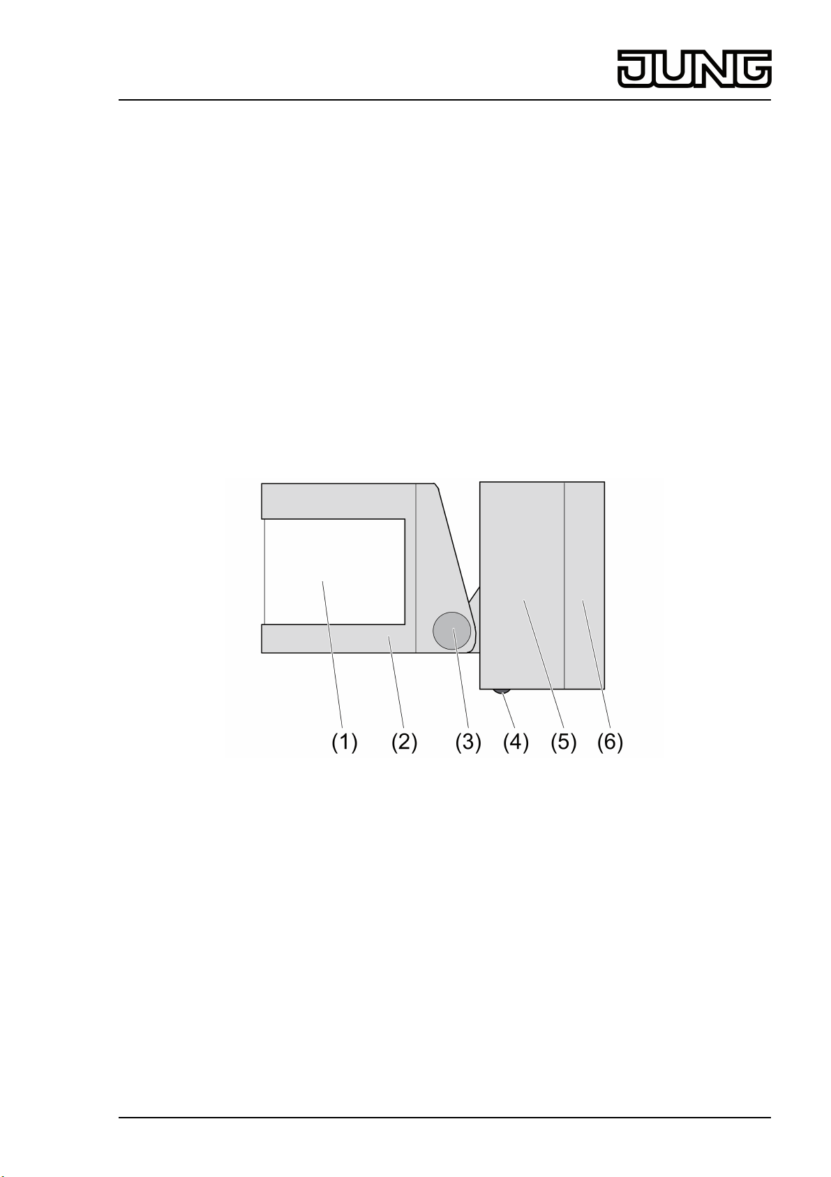
2 Device components
Figure 1
(1) Sensor window
(2) Sensor head
(3) Turning knuckle
(4) red LED
(5) Connection socket
(6) Base plate
3 Function
System information
By statute, the transmitting power, the reception characteristics and the antenna cannot be
changed.
The range of a radio system from the transmitter to the receiver depends on various
circumstances.
The range of the system can be optimised by selecting the optimal installation location, taking
into account the structural circumstances.
32519743
J0082519743
1/12
15.08.2016
Page 2
Radio Management
Radio observer 180
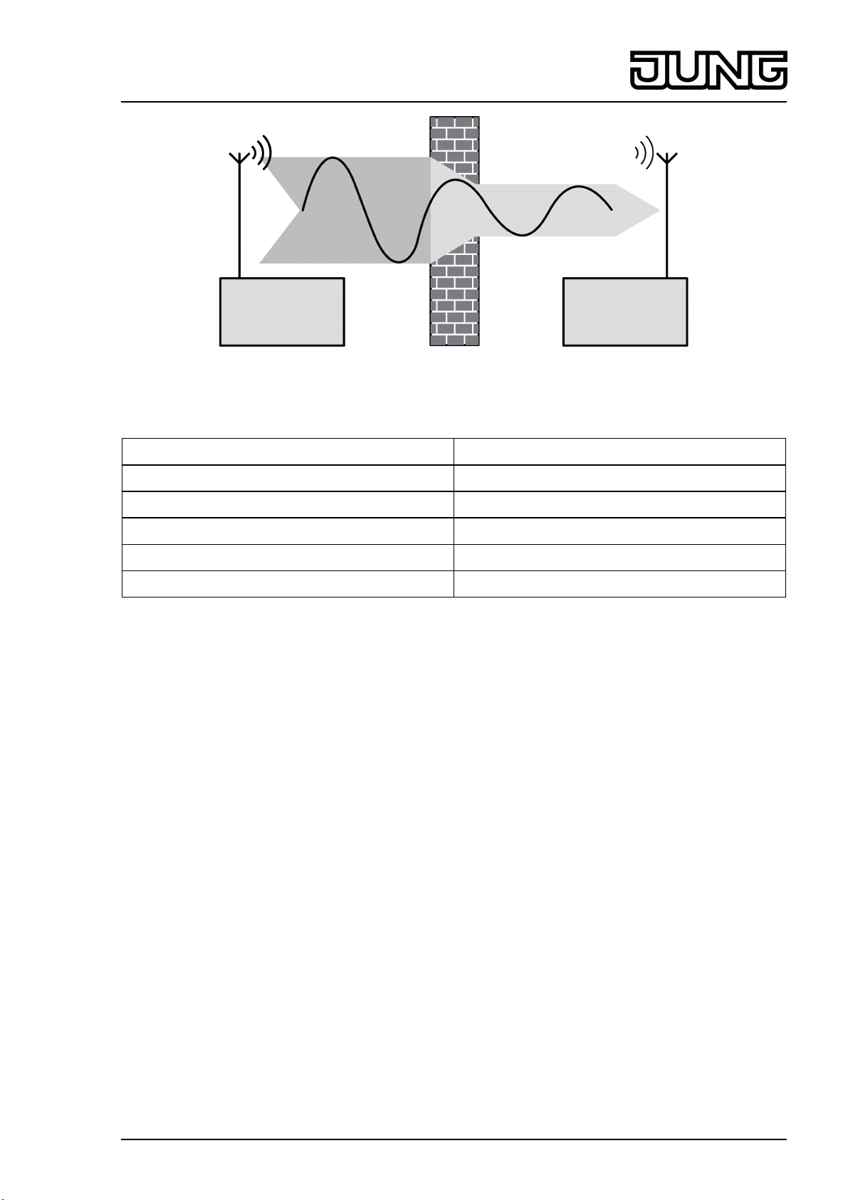
Figure 2: Reduced range due to structural obstacles
Example of penetration of various materials:
Material Penetration
Wood, Plaster, Plasterboard approx. 90%
Brick, Chipboard approx. 70%
Reinforced concrete approx. 30%
Metal, Metal grid approx. 10%
Rain, Snow approx. 1-40%
Intended use
- Motion detector for automatic switch-on of lighting depending on heat motions and ambient
brightness
- Operation in conjunction with radio power pack and suitable radio actuators
- Surface-mounting
i The motion detector is not secured against tampering, and is therefore not suitable for use
in alarm systems.
Product characteristics
- The motion detector detects heat motions caused by people, animals and inanimate
objects.
- Day operation: Motion detection is switched-off. Motion detector measures the lightning
strength every 8 seconds. If a value under 80 lux is determined, then Night mode is started
after a locking time of approx. 1 minute.
- Night mode: If motion is detected, the motion detector measures the lighting strength,
evaluates it and sends a radio telegram to the receiver. If there is a lighting strength of
over 200 lux, the motion detector switches to Day mode.
- Switch-on time settable with radio power pack. If radio switching or dimming actuators are
used, then dependent on the switch-on time set in the actuator.
- Brightness value can be set in the radio power pack
- Detection area can be limited with push-on cover.
- Battery-powered device
32519743
J0082519743
2/12
15.08.2016
Page 3
Radio Management
Radio observer 180
4 Information for electrically skilled persons
4.1 Fitting and electrical connection
CAUTION!
Heat radiation too high.
Destruction of the sensors.
Align the device so that no direct sunshine hits the sensor window.
Do not place the device in the sun.
Selecting the installation location
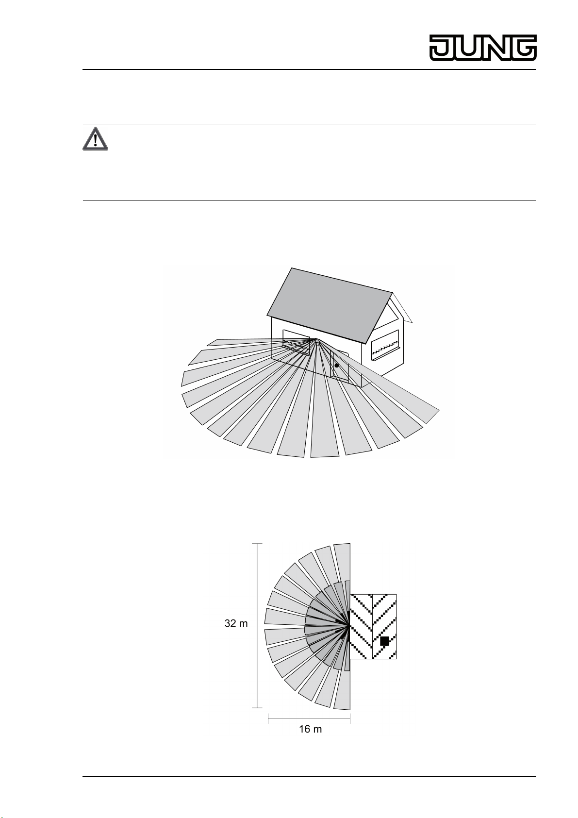
The motion detector possesses a tight, semi-circular detection area with 3 levels
and 144 switching segments (figure 3).
Figure 3: Motion detector detection area
Several basic principles must be taken into account when selecting the installation location.
o Select a vibration-free installation location; vibrations can lead to unwanted switching.
Figure 4: Detection area, top view
32519743
J0082519743
3/12
15.08.2016
Page 4
Radio Management
Radio observer 180
Size of the detection area: approx. 16 m x 32 m. The grey values in the figure (figure 4)
indicated the 3 monitoring levels.
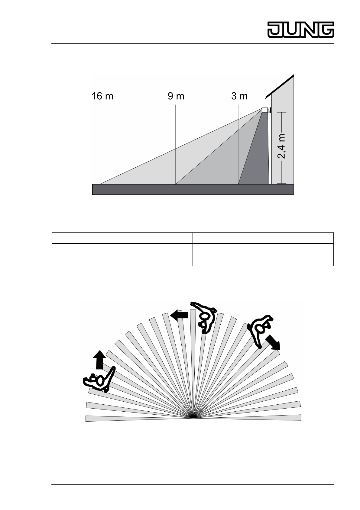
Figure 5: Detection area, side view
The 3 monitoring levels are defined as follows (figure 5):
Close range approx. 0 m - 3 m
Mid range approx. 3 m - 9 m
Long range approx. 9 m - 16 m
The specified range relates to an installation height of 2.40 m, sensor head not tilted, direction
of movement sideways to motion detector and sufficient temperature difference between body
and environment.
Figure 6: Installing the motion detector laterally to the direction of movement
For optimum range, install the motion detector at a height of 2.40 m and to the side of the
walking direction, otherwise range restrictions may be incurred (figure 6).
32519743
J0082519743
4/12
15.08.2016
Page 5

Radio Management
Radio observer 180
o Avoid sources of interference in the detection area, e.g. animals, branches moved by the
wind, motor vehicles or lamps. If necessary, limit the detection area with the supplied pushon cover (see chapter Limiting the detection area).
Figure 7
o Do not install the motion detector directly above a luminaire. A cooling lamp could be
detected as a heat change causing additional switch-on (figure 7).
o Do not touch the sensor window.
Install the motion detector on the wall
Figure 8
o Tilt the sensor head downwards. Slacken the screw on the connection socket (5) (figure 8).
o Remove the base plate (6) from the connection socket.
32519743
J0082519743
5/12
15.08.2016
Page 6

Radio Management
Radio observer 180
Figure 9
o Open the condensation water hole (7) in the base plate, except in case of installation in
dusty rooms (figure 9).
Figure 10
o Fasten the base plate (6) with 2 screws (figure 10).
o Connect the battery. Ensure correct polarity.
Motion detector is in the walking test/teach mode (see chapter Teaching the motion
detector in the radio receiver).
o Run the battery cable (10) around the screw dome (11) (see chapter Changing the battery).
Ensure that no cables are squashed.
o Place the connection socket (5) on the base plate and screw it tight.
o After installation, remove the attached cover panel. It is used as transport and installation
protection and to limit the detection area.
32519743
J0082519743
6/12
15.08.2016
Page 7

Radio Management
Radio observer 180
Mounting the motion detector under the ceiling
Figure 11
For mounting under ceilings, use a separate accessory part "Installation bracket".
o Fastening the installation bracket (8) to the ceiling with 2 screws (figure 11).
o Carry out the remaining installation as described above.
Changing the battery
WARNING!
Risk of chemical burns.
Batteries can burst and leak.
Replace batteries only with an identical or equivalent type.
o Slacken the screw on the connection socket (5) (figure 8).
o Remove the base plate (6) from the connection socket.
o Remove the void battery.
32519743
J0082519743
Figure 12
7/12
15.08.2016
Page 8

Radio Management
Radio observer 180
o Connect the new battery (9). Ensure correct polarity.
o Run the battery cable (10) around the screw dome (11). Ensure that no cables are
squashed.
o Place the connection socket (5) on the base plate and screw it tight.
i Approx. 1 minute after inserting the battery, the motion detector is in the walking test/teach
mode for approx. 10 minutes (see chapter Teaching the motion detector in the radio
receiver). No actuator may be in programming mode during this time. Otherwise
undesirable teaching will take place.
4.2 Commissioning
Teaching motion detector in radio receiver
In order for a receiver to understand a radio telegram from the motion detector, the receiver has
to "learn" this radio telegram. The motion detector can be taught in any number of radio
receivers. The teaching procedure only results in an assignment in the radio receiver.
When teaching a radio transmitter, the range of the receiver is reduced to about 5 m. The
distance between the radio receiver and the transmitter being taught should therefore be
between 0.5 m and 5 m.
o Disconnect the battery from the connection terminal for approx. 2 minutes.
o Reconnect the battery.
Figure 13
The red LED (4) lights up for approx. 1 minute(figure 13). Then the motion detector is in
walking test/teach mode for approx. 10 minutes. This is displayed by rapid flashing of the
red LED. In this mode the motion detector evaluates motions regardless of the brightness.
Every telegram transmitted here can be taught in the radio receiver.
o Test the detection area by walking over it and turn or tilt the sensor head if necessary (see
"Adjusting the detection area").
Each telegram transmitted switches the receiver on for approx. 2 seconds.
i If the motion detector does not detect any motion for approx. 2 minutes, then it
automatically exists the walking test / teaching mode.
o Switch radio receiver to programming mode (see instructions for receiver).
o Make a movement in the detection area of the motion detector, so that it sends a teach
telegram.
The red LED flashes approx. 4 times.
The radio receiver acknowledges the teaching procedure (see instructions for the receiver).
o Exit programming mode of the radio receiver (see instructions for the receiver).
32519743
J0082519743
8/12
15.08.2016
Page 9

Radio Management
Radio observer 180
The motion detector has now been taught to the radio receiver.
i For as long as the motion detector is in walking test/teach mode, each movement in the
detection area switches the lighting on briefly, irrespective of the brightness.
Adjusting the detection area
During the walking test/teach mode, the detection area should be adjusted (see chapter
Teaching the motion detector ot the radio receiver).
CAUTION!
Heat radiation too high.
Destruction of the sensors.
Align the device so that no direct sunshine hits the sensor window.
Do not place the device in the sun.
Figure 14: Turning and tilting the sensor head
o Pace off the detection area, paying attention to reliable detection and interference sources.
o Adjust the detection area to the local conditions by turning (12) and tilting (13) the motion
detector. The gradings on the motion detector housing mean that the settings can be
reproduced at any time (figure 14).
Adjusting the sensitivity
Figure 15
32519743
J0082519743
9/12
15.08.2016
Page 10

Radio Management
Radio observer 180
The sensitivity of the motion detector can be adjusted using the adjuster SENS. (figure 15).
o Select the greatest sensitivity.
o Measure the detection area. For this, it might be necessary to use the walking test mode
(see Teaching the motion detector in the radio receiver).
o If there are unwanted switching operations, reduce the sensitivity.
Limiting the detection area
Unrequired detection areas can be hidden using the cover panel. See (figure 16) and
(figure 17).
(14) Hidden area
(15) Monitored area
Figure 16: Hiding the side areas
Figure 17: Hiding the long range
i To hide the long range area, cut out the bottom slats of the cover panel and leave the top
cover panel slats alone.
32519743
J0082519743
10/12
15.08.2016
Page 11

Radio Management
Radio observer 180
Figure 18: Cutting out the cover panel
o Cut out the cover panel (18) (figure 18).
o Push the cover panel onto the sensor head (2).
5 Appendix
Remove empty batteries immediately and dispose of in an environmentally friendly
manner. Do not throw batteries into household waste. Consult your local authorities
about environmentally friendly disposal. According to statutory provisions, the end
consumer is obligated to return used batteries.
5.1 Technical data
Rated voltage DC 9V
Battery type Alkaline 6LR 61
Ambient temperature -25 ... +55°C
Degree of protection IP 55
Sensor evaluation
Brightness range 3 ... 200lx
Tolerance ± 50%
Night operation < 80lx
Day mode > 200lx
Sensitivity 20 ... 100%
Installation height approx. 2.40m
Detection angle 180°
Detection area approx. 16 x 32 m
Radio frequency 433.05MHz ... 434.79MHz
Transmitting range in free field typ. 100m
Transmission capacity < 10mW
5.2 Troubleshooting
After transmission, the LED on the motion detector flashes 10 times or the red LED on
the radio power pack lights up.
Cause: battery in the motion detector is almost empty.
Change battery (see section changing the battery).
Motion detector does not respond.
Cause 1: Ambient brightness too high.
Adjust the brightness value on the radio power pack (see radio power pack instructions).
32519743
J0082519743
11/12
15.08.2016
Page 12

Radio Management
Radio observer 180
Cause 2: The locking time for the transition between Day and Night mode has not yet elapsed.
Wait approx. 1 minute until the locking time has elapsed.
Cause 3: Radio range exceeded.
Check the installation situation. Structural obstacles reduce the range.
Using a radio repeater.
Cause 4: battery in the motion detector is empty.
Change battery (see section changing the battery).
Motion detector responds permanently.
Cause 1: Sensitivity of the motion detector is set too high.
Reduce the sensitivity.
Cause 2: the motion detector is in the walking test / teaching mode.
Without movement in the detection area wait 2 minutes, otherwise wait 10 minutes. After
that the walking test / teaching mode is exited automatically.
Cause 3: There is constant movement in the detection area of the motion detector.
Eliminate cause of the continuous motion.
5.3 Conformity
Albrecht Jung GmbH & Co. KG hereby declares that the radio system type
Art. No. FW180WW
corresponds to the directive 2014/53/EU. You can find the full article number on the device. The
complete text of the EU Declaration of Conformity is available under the Internet address:
www.jung.de/ce
5.4 Warranty
The warranty follows about the specialty store in between the legal framework as provided for
by law.
ALBRECHT JUNG GMBH & CO. KG
Volmestraße 1
58579 Schalksmühle
GERMANY
Telefon: +49 2355 806-0
Telefax: +49 2355 806-204
kundencenter@jung.de
www.jung.de
32519743
J0082519743
12/12
15.08.2016
 Loading...