

Page 1
Radio Management Universal radio transmitter
Ref.-no.: FUS22UP
Operating Instructions
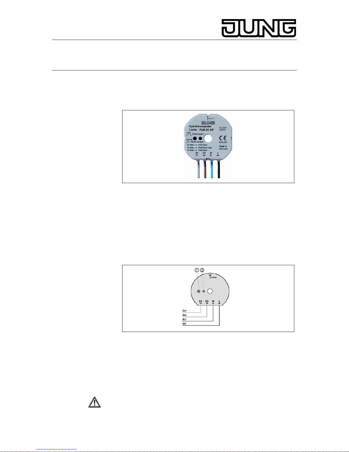
Universal radio-control transmitter with
L conductor
1. Function
The universal radio-control transmitter can be used to extend an existing
electrical installation by the possibility of transmitting 230 V control
commands by radio. The transmitter can be operated for switching,
dimming or blind/shutter control functions.
When mains voltage (AC 230 V~) is applied to inputs (E1, E2), the
universal radio-control transmitter transmits radio telegrams which are
evaluated by all radio-control receivers.
For selection and indication of the mode of operation, the device is
equipped with a pushbutton (1) and an LED (2).
A)
The universal radio-control transmitter has 4 modes of operation:
Mode A: 2 Kanal Dimmen (Toggle) (E1 und E2)
Mode B: 2 Kanal Schalten (E1 und E2)
Mode C: 1 Kanal Dimmen (E1/E2)
Mode D: 1 Kanal Jalousie (E1/E2)
2. Safety Instructions
Attention: Electrical equipment must be installed and fitted by
qualified electricians only.
Stand: Apr-08 325 479 13
Page 2
Radio Management Universal radio transmitter
Ref.-no.: FUS22UP
Do not connect motors in parallel with the universal radiocontrol
transmitter.
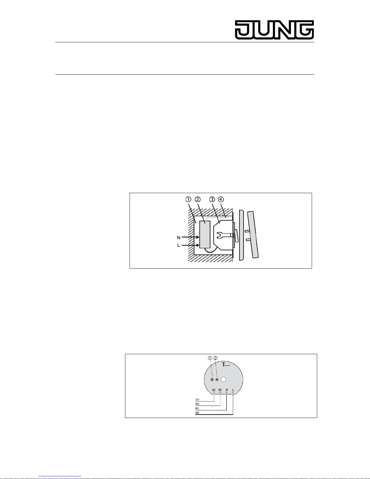
3. Fitting
Install the universal radio-control transmitter (2) in a deep flushmounting
box (1) behind a flush-mounting insert (3) (60 mm-deep mounting box
recommended).
Important: When installed outside flush-mounting boxes, the device
must be sufficiently protected against shock hazards by
installing it, for instance, in a surface-mounted distribution box.
Antenna
For maximum transmission range, the antenna (4) should be stretched
out to full length and not be left coiled up. Keep away as far as possible
from large metal surfaces such as metallic door frames. Do not shorten or
lengthen the antenna and do not strip off the insulation.
B)
4. Installation and adjustment
Depending on wiring and on the selected mode of operation, the
universal radio-control transmitter transmits radio telegrams, e.g.:
„channel 1 = switch on“.
Connect the wires as follows:
E1: input 1 (grey)
E2: input 2 (brown)
N: N-conductor (blue)
L: phase conductor (black)
C)
2
Page 3
Radio Management Universal radio transmitter
Ref.-no.: FUS22UP
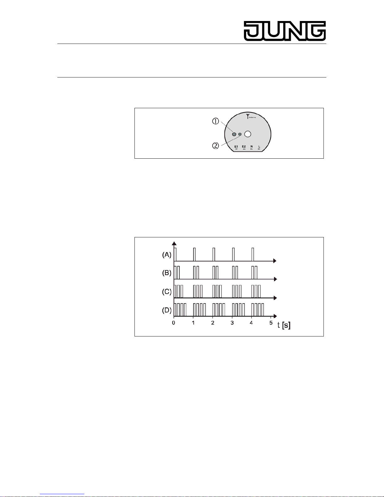
5. Modes of operation
The universal radio-control transmitter has 4 modes of operation which
can be selected or indicated with pushbutton (1).
D)
The modes are signalled by the LED das follows:
A) 2-channel dimming, toggling (E1 and E2)
1 brief flashes per second for 5 s altogether
B) 2-channel switching (E1 and E2))
2 brief flash per second for 5 s altogether
C) 1- channel dimming (E1/E2))
3 brief flashes per second for 5 s altogether
D) 1- channel blind/shutter (E1/E2)
4 brief flashes per second for 5 s altogether
E)
Indicating actual mode of operation
To indicate the actual mode of operation, depress pushbutton (1) briefly
(< 0,5 s). The mode in which the device is actually operating is then
signalled by the LED (see previous page).
Changing the modes of operation
Depress pushbuttonc for at least 1 s. With each long press of the button,
the universal transmitter changes between A, B, C and D. Wait until
signalling has ended before pressing the pushbutton again.
Mode A: 2-channel dimming, toggling (E1 and E2)
3
Page 4

Radio Management Universal radio transmitter
Ref.-no.: FUS22UP
F)
For independent control of two radio-control dimming actuators.
Connection of conventional pushbuttons (n.o. contacts):
a press on the button switches over (toggles) the type of telegram from
the transmitter:
brief press (< 1s): switching on / off
lon press (≥ 1 s): lamp brighter / darker
Imprtant: Switching over (toggling) of the telegram type (on/off, brighter/
darker) is effected in the transmitter. When a receiver has been
operated locally or by another transmitter, it may therefore be
necessary to actuate the universal radio-contol transmitter twice
in order to obtain the desired reaction.
Mode B: 2-channel switching (E1 and E2)
For independent control of two radio-control switching actuators.
Connection of conventional switches (n.o. contact):
G)
the universal transmitter transmits switch-on telegrams when closed and
switch-off telegrams when opened (see fig. G).
Connection of conventional pushbuttons (n.o. contact):
the transmitter is in the special „doorbell“ mode and transmits switch-on
telegrams when closed and switch-off telegrams when opened (see fig.
H).
4
Page 5

Radio Management Universal radio transmitter
Ref.-no.: FUS22UP
H)
Important This mode of operation is not suited for radio-control
pushbutton actuators.
Modus C: 1 channel dimming (E1/E2)
I)
For operation of one radio-control dimming actuator.
Connection of conventional pushbuttons (n.o. contacts):
Actuation:
T1 < 1s: switch on
T1 ≥ 1 s: lamp brighter
T2 < 1 sswitch off
T2 ≥ 1 s: lamp darker
Important:: A long press (≥ 1 s) of T2 when the load is off causes suitable
dimmers to switch on with their minimal brightness (night light).
Mode D: 1-channel blind/shutter (E1/E2)
J)
5
Page 6

Radio Management Universal radio transmitter
Ref.-no.: FUS22UP
K)
For controlling of a radio-control blind/shutter actuator.
Connection of a blind/shutter switch (fig. J) or a motor control insert (fig.
K):
On closing of switch J1, the radio-control universal transmitter transmits
telegrams for raising / lowering blinds and shutters. The blind/shutter
stops when the switch is opened.
Important: The radio-control universal transmitter must not be connected
in parallel with blind/shutter motor.
6. Programming of radio-control receivers
A universal radio-control transmitter channel can be programmed into an
unlimited number of radio receivers. Programming information is stored
only in the radio-control receiver.
During programming of a radio-control transmitter, the sensitivity of the
receivers is reduced to approx. 5 m. The distance between the receiver
and the transmitter to be programmed should therefore be between 0.5 m
and 5 m.
Procedure
1. Switch the radio-control receiver into the programming mode (see
„Radio-control receiver“ operating instructions)
2a. Programming of operating mode A, C or D
Actuate the connected pushbutton or switch for at least 1 s.
2b. Programming of operating mode B
The switching telegrams of operating mode B are not suitable for
programming. Set the flush-mounted radio-control transmitter with L
conductor therefore at first to operating mode A. Press or actuate the
corresponding buttons or switches for at least 1 s. Then go back to
operating mode B.
3. Switch the radio-control receiver back into the operating mode (see
„Radio-control receiver“ operating instructions).
7. Clearing a programmed channel
Reprogramming of the transmit channel to be cleared in the same mode
of operation deletes the assignment stored in the radiocontrol receiver.
6
Page 7

Radio Management Universal radio transmitter
Ref.-no.: FUS22UP
8. Radio Transmission
Radio transmission takes place on a non-exclusive path. Therefore,
interference cannot be excluded. This type of radio transmission is
not suitable for safety applications such as emergency stops or
emergency calls.
The range of a radio-control system depends on transmitter power,
receiver characteristics, air humidity, fitting height and building conditions.
The figure illustrates the penetration of building materials by radio waves:
Dry material Permeability
Timber, gypsum, gypsum-plasterboards approx. 90 %
Brickwork, particle boards approx. 70 %
Reinforced concrete approx. 30 %
Metal, metal grating, aluminium
lamination
approx. 10 %
Rain, snow approx. 0 – 40
%
L)
Radio operation
- The inter-connection of this radio system with other communication
networks must comply with national legislation.
- This radio system must not be used for communication beyond
property boundaries.
- Operation in Germany is subject to the relevant regulations
(Amtsblatt Vfg 73/2000).
- If utilized in conformity with its designated use, this unit fulfils the
requirements of the R&TTE Directive (1999/5/EC). The complete
declaration of conformity can be found in the Internet under:
www.jung.de/ce.
The universal radio-control transmitter may be operated in all
countries of the EU and the EFTA.
7
Page 8

Radio Management Universal radio transmitter
Ref.-no.: FUS22UP
9. Specifications
Power supply : AC 230 V ~
Transmit frequency : 433.42 MHz, ASK
Transmitting range : appr. 100 m (in free space)
Operating temperature : ca. –20 °C … +55 °C
Type of protection : IP 20
Dimension (Ø x H) : 52 mm x 23 mm
Technical specifications subject to change.
10. Guarantee
We accept the guarantee in accordance with the corresponding legal
provisions.
Please return the unit postage paid to our central service
department giving a brief description of the fault:
ALBRECHT JUNG GMBH & CO. KG
Service-Center
Kupferstr. 17-19
D-44532 Lünen
Service-Line: +49 (0) 23 55 . 80 65 51
Telefax: +49 (0) 23 55 . 80 61 89
E-Mail: mail.vki@jung.de
General equipment
Service-Line: +49 (0) 23 55 . 80 65 55
Telefax: +49 (0) 23 55 . 80 62 55
E-Mail: mail.vkm@jung.de
KNX equipment
Service-Line: +49 (0) 23 55 . 80 65 56
Telefax: +49 (0) 23 55 . 80 62 55
E-Mail: mail.vkm@jung.de
8
 Loading...