

Page 1
eNet radio push-button controller 1-10 V 1-gang mini
eNet radio push-button controller 1-10 V 1-gang mini
Art. No. : FMST50UP
Operating instructions
1 Safety instructions
Electrical devices may only be mounted and connected by electrically skilled
persons.
Serious injuries, fire or property damage possible. Please read and follow manual fully.
Danger of electric shock. Always disconnect before carrying out work on the devise or
load. In so doing, take all the circuit breakers into account, which support dangerous
voltages to the device and or load.
Danger of electric shock. Device is not suitable for disconnection from supply voltage.
These instructions are an integral part of the product, and must remain with the end
customer.
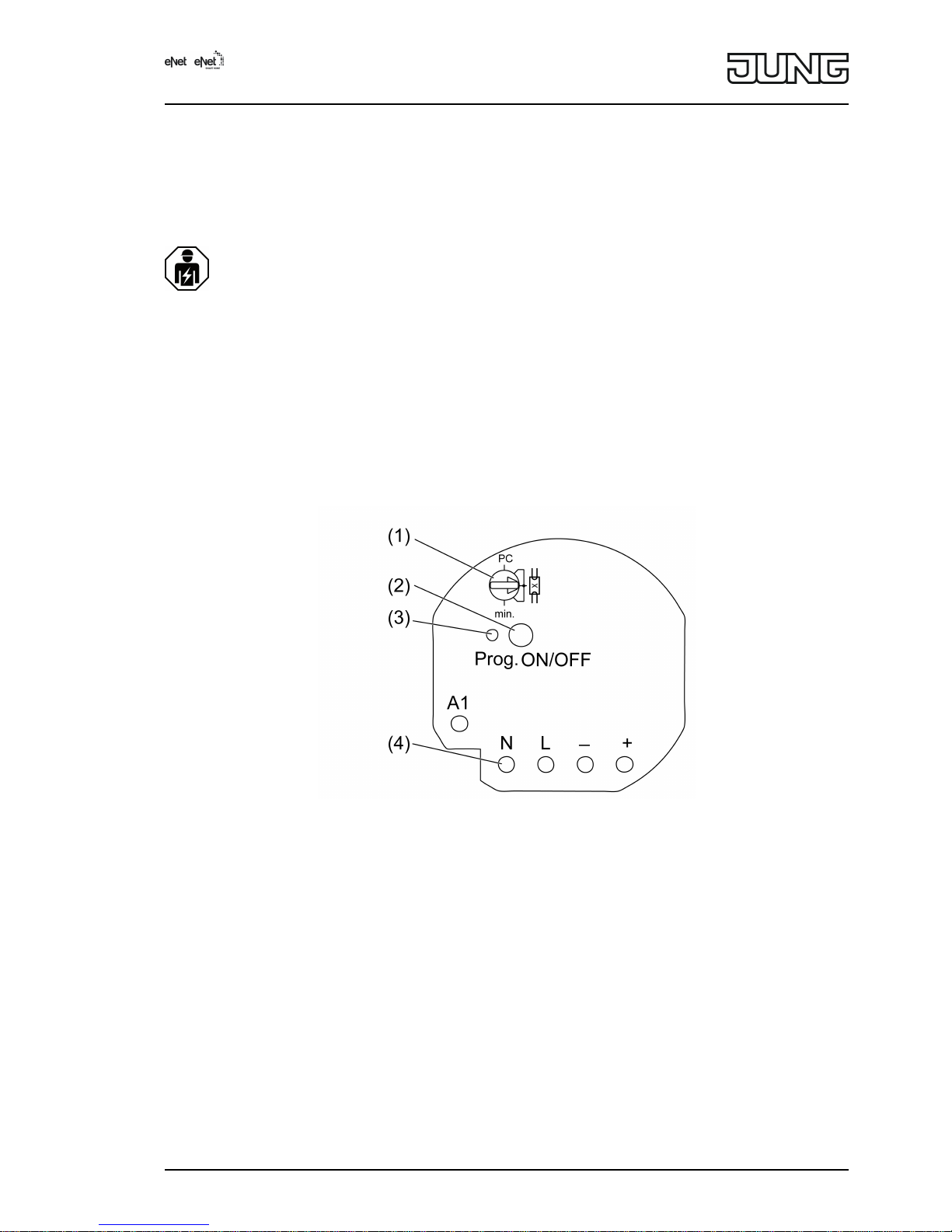
2 Device components
Figure 1: Device components
(1) Operating mode switch
(2) Button Prog
(3) Status LED
(4) Measuring points for voltage measurement, terminals rear-mounted
3 Function
Intended use
- Switching and brightness setting of luminaires with 1-10 V interface
- Operation with suitable radio transmitters
- Mounting in appliance box according to DIN 49073 in combination with a suitable cover
- Installation in surface-mounted housing or panel-mounted housing (accessories) for
suspended ceilings
Product characteristics
- Switch-on brightness can be saved permanently
- Minimum brightness can be saved permanently
1/12
82581023
J0082581023
29.03.2017
Page 2

- Scene operation possible
- Status indicator of the 1-10 V subscribers via LED
- Status feedback to radio transmitter
- 1-10 V subscribers switchable with Prog button
- 1-10 V interface is protected against reverse polarity
Can be set with eNet server:
- Maximum brightness
- Dimming speed
- Switch-on delay / switch-off delay
- Dim up/dim down ramp
- Switch-off warning
- Operation locks
- Continuous on, Continuous off
- Hotel function
- Run-on time
- Light control
i If settings are changed with the eNet server, operation and signalling could vary from what
is described here.
i The parameter list is in the Internet in the documentation for this device.
Supplementary functions with eNet server:
- Update of the device software
- Repeater function
- Reading of error memory
Response after mains voltage return
The response after mains voltage return can be configured with the eNet Server. Default
setting: Off.
4 Operation
Operation with radio transmitters
Operation is with radio transmitters, please observe the radio transmitter instructions.
5 Information for electrically skilled persons
5.1 Fitting and electrical connection
DANGER!
Electrical shock when live parts are touched.
Electrical shocks can be fatal.
Before carrying out work on the device or load, disengage all the
corresponding circuit breakers. Cover up live parts in the working environment.
Mounting and connecting actuator
To ensure good transmission quality, keep a sufficient distance from any possible sources of
interference, e.g. metallic surfaces, microwave ovens, hi-fi and TV systems, ballasts or
transformers.
2/12
82581023
J0082581023
29.03.2017
eNet radio push-button controller 1-10 V 1-gang mini
Page 3

Figure 2: Connection example
i Ensure that the control cable is of the appropriate type, cross-section and routing for the
VDE specifications for 250 V cable, control voltage has basic insulation.
i The control cable and load cable can be run in a shared cable, e.g. NYM J 5×1.5.
o Connect actuator (5) and 1-10 V ballasts (6) as shown in the connection example
(figure 2). At the same time, note the information given by the manufacturers of the ballast.
o If multiple circuit breakers supply dangerous voltages to the device or load, couple the
miniature circuit breakers or label them with a warning, to ensure disconnection is
guaranteed.
o Insert the actuator in the appliance box in such a way that the Prog button (2) and status-
LED (3) are visible.
Figure 3: Operating mode switch
Position Description
PC Operating mode, parameter set with eNet
server *)
G 1-10 V operation
min. Setting of the minimum brightness
*) If the operating mode switch is turned from the position PC, the operating mode and
parameters are set to the default setting. The settings made with the eNet Server will be
lost.
o Set the operating mode switch (1).
3/12
82581023
J0082581023
29.03.2017
eNet radio push-button controller 1-10 V 1-gang mini
Page 4
o Switch on mains voltage.
i The 1-10 V ballasts can be switched by briefly pressing the Prog button.
Status-LED (3) lights up: switched on
Status LED (3) off: switched off
o Perform commissioning.
o Mount the cover.
5.2 Commissioning
DANGER!
Electrical shock when live parts are touched.
Electrical shocks can be fatal.
During commissioning, cover the parts carrying voltage on radio transmitters
and actuators and in their surrounding area.
i The actuator can also be commissioned with eNet Server as an alternative to the
commissioning described here.
Connecting to radio transmitters
Load is switched off.
o Press the Prog button for longer than 4 seconds.
The status LED (4) flashes after 3 seconds. The actuator is in programming mode for
approx. 1 minute.
o Switch radio transmitter to programming mode (see radio transmitter instructions).
o Trigger telegram on the radio transmitter.
The status LED lights up for 5 seconds.
The actuator is connected to the radio transmitter. The actuator and radio transmitter exit
the programming mode automatically.
i If the status LED of the control unit flashes 3 times at 1-second intervals for
approx. 5 seconds, then the programming operation was not successful. All the memory
locations in the actuator or radio transmitter are occupied.
i All On and All Off buttons of a radio transmitter are connected to the actuator automatically
as soon as the first connection to the radio transmitter takes place. Scene buttons must be
connected separately.
Disconnecting connection to a radio transmitter
o Carry out the same steps as when connecting (see Connecting to radio transmitter).
The status LED (3) flashes quickly for 5 seconds. The actuator is disconnected from the
radio transmitter. The actuator and radio transmitter exit the programming mode
automatically.
i If there several connections or scene buttons for a radio transmitter, all connections must
be disconnected individually.
i All On and All Off buttons of a radio transmitter are disconnected automatically as soon as
the last connection to the radio transmitter is disconnected. Manual disconnection is not
possible.
Resetting actuator to default setting
All connections to radio transmitters are disconnected and parameters are reset to default
setting.
i The connections in the radio transmitters are preserved and must be deleted separately.
Load is switched off.
o Press the Prog button for at least 20 seconds.
The status LED flashes after 4 seconds. After 20 seconds the status LED flashes faster.
o Release Prog button and press briefly once again within 10 seconds.
The status LED flashes more slowly for approx. 5 seconds.
4/12
82581023
J0082581023
29.03.2017
eNet radio push-button controller 1-10 V 1-gang mini
Page 5

The actuator is reset to default setting.
Setting the minimum brightness
The minimum brightness can be set within a range of approx. 1...67 %, if, e.g. the light flickers
at low brightness or to compensate for differences in brightness.
o Turn operating mode switch (1) to the min. position.
o Adjust brightness with the radio transmitter.
o Turn operating mode switch to the original position again.
When leaving the position min., the minimum brightness is saved.
Save switch-on brightness
o Switch on light.
o Adjust brightness with the radio transmitter.
o Press button Prog (2) for longer than 4 seconds.
The light switches off briefly and then switches on again to the new switch-on brightness.
Switch-on brightness is saved.
i Alternatively, the switch-on brightness can be saved with a radio transmitter, e.g. wall
transmitter.
6 Appendix
6.1 Technical data
Rated voltage AC 230V~
Mains frequency 50 / 60Hz
Standby power max. 0.5W
Ambient temperature -25 ... +70°C
Contact type µ
Control voltage 0.5 ... 11V
Control current max. 50mA
Switching current
Ohmic 6A
Fluorescent lamps 3AX
Minimum switching current 100mA
Connected load
Ohmic load 1380W
Capacitive load 690VA (560 µF)
Connection
single stranded 0.75 ... 4mm²
Finely stranded with conductor sleeve 0.75 ... 2.5mm²
Dimensions Ø×H 53×28 mm
Total length power cable max. 100m
Total length of control cable max. 100m
Radio frequency 868.0 ... 868.6MHz
Transmission capacity max. 20mW
Transmitting range in free field typ. 100m
Receiver category 2
6.2 Parameter list
The device parameters can be changed with the eNet server:
Device and channels
Parameters Setting options, Basic
setting
Explanations
5/12
82581023
J0082581023
29.03.2017
eNet radio push-button controller 1-10 V 1-gang mini
Page 6

Function Light, unused
Basic setting: Light
Light
The channel is integrated for
the "Lighting" central function
in the eNet SMART HOME
app.
Unused
The channel is not displayed
in the eNet SMART HOME
app and is disabled for use in
the commissioning interface.
Operating mode Normal operation
Continuous on
Continuous off
Basic setting: Normal
Operation
Normal operation
The output can be operated
with radio transmitters and the
Prog button.
Continuous on
The output switches to
continuously "On". All
operations of radio
transmitters and the Prog
button are ignored.
Continuous off
The output switches to
continuously "Off". All
operations of radio
transmitters and the Prog
button are ignored.
Advanced device settings
Parameters Setting options, Basic
setting
Explanations
Manual commissioning On, Off
Basic setting: On
Blocks manual commissioning
for the device channel.
Note: In the "Off" setting, the
device cannot be reset to the
factory setting.
Repeater mode On, Off
Basic setting: Off
In addition to its other
functions, the device can be
used as a repeater. In the
"On" setting, the device
repeats all the received
telegrams.
Channel settings
Parameters Setting options, Basic
setting
Explanations
Switch-on brightness 1...100 %
Basic setting: 100 %
During brief operation, the
output switches on at the set
switch-on brightness.
Note: If the value is above the
set maximum brightness or
below the minimum
brightness, then the system
will switch to the appropriate
limit value.
6/12
82581023
J0082581023
29.03.2017
eNet radio push-button controller 1-10 V 1-gang mini
Page 7

Minimum brightness 1...67 %
Basic setting: 5 %
Specifies the minimum
settable brightness.
Note: If parameters or scene
values are set to a level lower
than the minimum brightness,
then the system will dim to
minimum brightness.
Maximum brightness 75...100 %
Basic setting: 100 %
Specifies the maximum
settable brightness.
Note: If parameters or scene
values are set to a level higher
than the maximum brightness,
then the system will dim to
maximum brightness.
Dimming adjustment time 1…60 s
Basic setting: 4 s
Time from minimum
brightness until reaching
maximum brightness (dimming
speed).
Switch-on delay 0 s … 24 h
Basic setting: 0 s
The load switches on after a
delay. Repeated switch-on
commands restart the delay
time. If the load has not yet
been switched on due to the
delay when a switch-off
command comes, then the
load will remain off.
Note: The set time apply to
operation using radio
transmitters. The device is
switched immediately when
the Prog button is pressed.
Switch-off delay 0 s … 24 h
Basic setting: 0 s
The load switches off after a
delay. Repeated switch-off
commands restart the delay
time. If the load has not yet
been switched off due to the
delay when a switch-on
command comes, then the
load will remain on.
Note: The set time apply to
operation using radio
transmitters. The device is
switched immediately when
the Prog button is pressed.
Dim up ramp 0 s … 24 h
Basic setting: 0 s
Time between switch-on and
reaching switch-on brightness.
The light is switched on at
minimum brightness and then
dimmed to the switch-on
brightness.
Only applies to switch-on with
transmitters (short operation).
If scenes are recalled or
switching uses logic modules,
the switch-on brightness is
approached using so-called
soft dimming (not
configurable).
7/12
82581023
J0082581023
29.03.2017
eNet radio push-button controller 1-10 V 1-gang mini
Page 8

Dim down ramp 0 s … 24 h
Basic setting: 0 s
Time until reaching minimum
brightness. The light is
dimmed to minimum
brightness and then switched
off.
Only applies to switch-off with
transmitters (short operation).
If scenes are recalled or
switching uses logic modules,
the system switches off
directly.
Run-on time 0 s … 24 h
Basic setting: 0 s
As soon as a run-on time has
been entered, the actuator will
no longer remain on
permanently, but only for the
length of the run-on time. The
run-on time is restarted if
actuation is repeated. This
parameter is directly
connected to the "Manual
switch-off of run-on time"
parameter.
Note: The set time apply to
operation using radio
transmitters. The device is
switched immediately when
the Prog button is pressed.
Manual switch-off of the runon time
On, Off
Basic setting: Off
Allows manual switch-off of a
running run-on time. If the
parameter is switched off, then
a switch-off command will also
switch the actuator on. Only
visible if a run-on time was
set.
Operating hours 0...65535
Basic setting: Current value
The time is counted during
which the load is physically
switched on.
This parameter can be reset to
"0", for example after
exchanging the load.
The Reset button is used to
reset the meter to "0". The
device must be programmed
to apply the change.
Extended channel settings
Parameters Setting options, Basic
setting
Explanations
Operating mode Normal operation
Continuous on
Continuous off
Basic setting: Normal
Operation
see Device and channels
Manual commissioning On, Off
Basic setting: On
Blocks manual commissioning
for the device channel.
Note: In the "Off" setting, the
device cannot be reset to the
factory setting.
8/12
82581023
J0082581023
29.03.2017
eNet radio push-button controller 1-10 V 1-gang mini
Page 9

Local Operation On, Off
Basic setting: On
Blocks the output for operation
using the Prog button.
Behaviour on voltage return On
Off
Last value
Configured brightness
Basic setting: Off
Defines the behaviour of the
output after voltage return.
Brightness on voltage return 0...100 %
Basic setting: 100 %
Brightness value, set by the
output after voltage return
(mains voltage). The
parameter "Behaviour after
voltage return" must be set to
"Configured position".
Note: If the value is above the
set maximum brightness or
below the minimum
brightness, then the system
will switch to the appropriate
limit value.
Behaviour after the end of the
disabling function
On
Off
no change
Last value
Basic setting: No change
Behaviour of the output when
a block is removed.
Manual saving of the scene
values
On, Off
Basic setting: On
Disables the saving of the
current brightness value as
scene value in an actuator for
a command via a transmitter.
Switch-off warning On, Off
Basic setting: Off
If the switch-off warning is
active, then, during switch-off,
the systems dims to minimum
brightness within 30 seconds
and only then switches off. If
the parameter "Dim down
ramp" is configured as longer
than 30 s, then the length of
the dim down ramp is applied.
If, during the dim down
operation, another command
is given, e.g. switch on or
scene recall, then the switchoff warning stops and the
command is executed. A
switch-off command restarts
the time for the switch-off
warning.
Note: The set time apply to
operation using radio
transmitters. The device is
switched immediately when
the Prog button is pressed.
Priority, lock-out protection 0...4
Basic setting: 1
Specifies the priority for
recalling and removing a
scene of type Lock-out
protection for the channel.
Note: 1 is the highest priority
and 4 the lowest. 0 means no
priority.
9/12
82581023
J0082581023
29.03.2017
eNet radio push-button controller 1-10 V 1-gang mini
Page 10

Activate lock-out protection
brightness value
0…100 %
Basic setting: 0 %
Defines the behaviour of the
output on activating the lockout protection.
Deactivate lock-out protection
brightness value
0…100 %
Basic setting: 0 %
Defines the behaviour of the
output on deactivating the
lock-out protection. Only
visible when the priority for the
lock-out protection is 0.
Priority, restraint 0...4
Basic setting: 2
Specifies the priority for
recalling and removing a
scene of type Restraint for the
channel.
Activate forced operation
brightness value
0…100 %
Basic setting: 100 %
Defines the behaviour of the
output on activating the forced
operation.
Deactivate forced operation
brightness value
0…100 %
Basic setting: 0 %
Defines the behaviour of the
output on deactivating the
forced operation. Only visible
when the priority for the forced
operation is 0.
Priority, wind alarm 0...4
Basic setting: 3
Specifies the priority for
recalling and removing a
scene of type Wind alarm for
the channel.
Activate wind alarm brightness
value
0…100 %
Basic setting: 0 %
Defines the behaviour of the
output on activating the wind
alarm.
Deactivate wind alarm
brightness value
0…100 %
Basic setting: 0 %
Defines the behaviour of the
output on deactivating the
wind alarm. Only visible when
the priority for the wind alarm
is 0.
Priority, sun protection 0...4
Basic setting: 0
Specifies the priority for
recalling and removing a
scene of type Sun protection
for the channel.
Activate sun protection
brightness value
0…100 %
Basic setting: 100 %
Defines the behaviour of the
output on activating the sun
protection.
Deactivate sun protection
brightness value
0…100 %
Basic setting: 0 %
Defines the behaviour of the
output on deactivating the sun
protection. Only visible when
the priority for the sun
protection is 0.
Priority, twilight 0...4
Basic setting: 0
Specifies the priority for
recalling and removing a
scene of type Twilight for the
channel.
Activate twilight brightness
value
0…100 %
Basic setting: 100 %
Defines the behaviour of the
output on activating the
twilight function.
10/12
82581023
J0082581023
29.03.2017
eNet radio push-button controller 1-10 V 1-gang mini
Page 11

Deactivate twilight brightness
value
0…100 %
Basic setting: 0 %
Defines the behaviour of the
output on deactivating the
twilight function. Only visible
when the priority for the
twilight function is 0.
Switch off brightness
overshoot
On, Off
Basic setting: On
Allows automatic switch-off
according to the brightness. If
the parameter is On, then the
light controller switches off
automatically when the
brightness setpoint is greatly
exceeded.
Note: This parameter is not
yet active, as a light controller
has not yet been
implemented.
Switch on brightness
undershoot
On, Off
Basic setting: Off
Allows automatic switch-on
according to the brightness. If
the parameter is On, then the
light controller switches on
automatically when the
brightness setpoint is greatly
undershot. We recommend
only using the parameter in
connection with the parameter
"Switch-off on brightness
overshoot".
Note: This parameter is not
yet active, as a light controller
has not yet been
implemented.
Hotel function On, Off
Basic setting: Off
If the hotel function is
activated, the system will dim
to 20 % brightness when a
switch-off command is made.
Switch-off is only possible with
a forced position command.
Note: If the minimum
brightness is set to greater
than 20 %, then the system
dims to the set minimum
brightness when the hotel
function is activated.
Information window
In the Information window, the load can be controlled and the information about the device can
be displays.
Channel control/channel information
Display value Explanations
Current dimming value The load can be dimmed using the slider or a
brightness value entry.
Load state The load can be switched on or off.
Restraint Display of forced position status.
Operating hours Display of the operating hours since the last
restart in the Settings window Einstellungen.
11/12
82581023
J0082581023
29.03.2017
eNet radio push-button controller 1-10 V 1-gang mini
Page 12

6.3 Troubleshooting
Lamps switch to minimum brightness. No dimming is possible.
Cause 1: 1-10 V interface is connected in reverse polarity.
Connect the control cables with the correct polarity.
Cause 2: 1-10 V control cables have short-circuited.
Eliminate short-circuit.
Lamps switch to maximum brightness. No dimming is possible.
Cause: 1-10 V control cables are interrupted or not connected.
Connect the control cables correctly.
6.4 Accessories
Mounting adapter for mini housing Art. No. FM-EBG
eNet server for rail mounting Art. No. ENET-SERVER
6.5 Conformity
Albrecht Jung GmbH & Co. KG hereby declares that the radio system type
Art. No. FMST50UP
corresponds to the directive 2014/53/EU. You can find the full article number on the device. The
complete text of the EU Declaration of Conformity is available under the Internet address:
www.jung.de/ce
6.6 Warranty
The warranty follows about the specialty store in between the legal framework as provided for
by law.
ALBRECHT JUNG GMBH & CO. KG
Volmestraße 1
58579 Schalksmühle
GERMANY
Telefon: +49 2355 806-0
Telefax: +49 2355 806-204
kundencenter@jung.de
www.jung.de
12/12
82581023
J0082581023
29.03.2017
eNet radio push-button controller 1-10 V 1-gang mini
 Loading...