

Page 1
eNet radio repeater in SCHUKO housing
eNet radio repeater in SCHUKO housing
Art. No. : FMR100SGWW
Operating instructions
1 Safety instructions
Electrical devices may only be mounted and connected by electrically skilled
persons.
Serious injuries, fire or property damage possible. Please read and follow manual fully.
Adapter plugs may not be connected in series and must be easily accessible.
The radio communication takes place via a non-exclusively available transmission path,
and is therefore not suitable for safety-related applications, such as emergency stop and
emergency call.
These instructions are an integral part of the product, and must remain with the end
customer.
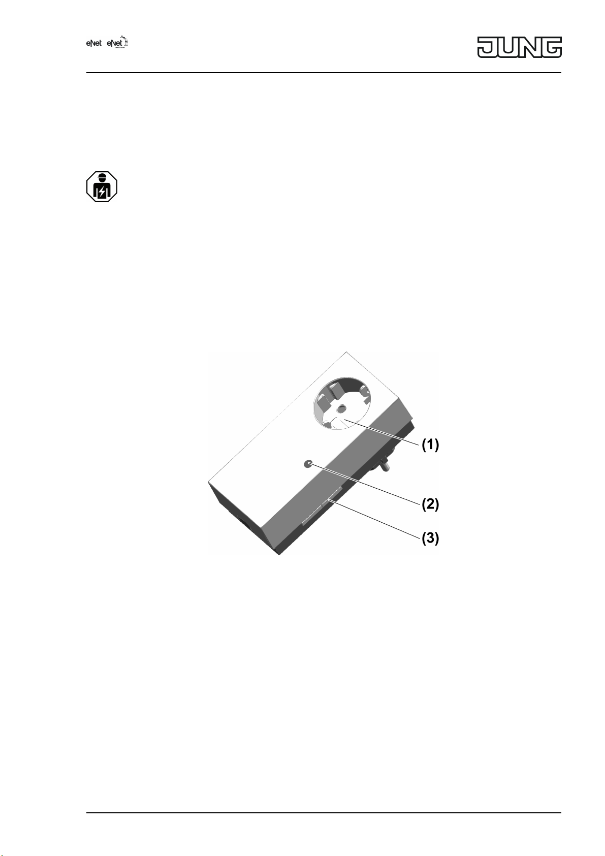
2 Device components
Figure 1: Repeater
(1) SCHUKO® socket with increased contact protection
(2) Red status LED, covered
(3) Prog button
3 Function
Intended use
- Receiving and repeating eNet radio telegrams
- Extending the range of radio transmitters and actuators
- Indoor mounting in SCHUKO® socket or socket with ground pin
Product characteristics
- Fully encrypted radio transmission (AES-CCM) from eNet Server software version 2.0
- Repeating of all received radio telegrams or only of selected radio transmitters and
actuators
- 125 transmitters/actuators can be connected
- Two repeaters are cascadable
82586533
J0082586533
1/5
27.03.2017
Page 2
eNet radio repeater in SCHUKO housing
- Signalling of telegram repetitions, status LED flashes for 50 ms
- With server: Disabling of manual commissioning
Function
The repeater has two operating modes:
- Repeating of all received radio telegrams.
No device may be connected to the repeater (as-delivered state)
- Repeating of the radio telegrams from selected devices.
The respective devices must be connected to the repeater.
i A radio telegram is only repeated twice in order to restrict the number of telegrams in a
system.
4 Information for electrically skilled persons
4.1 Fitting and electrical connection
Mounting
To ensure good transmission quality, keep a sufficient distance from any possible sources of
interference, e.g. metallic surfaces, microwave ovens, hi-fi and TV systems, ballasts or
transformers.
o Insert device into socket outlet.
4.2 Commissioning
DANGER!
Electrical shock when live parts are touched.
Electrical shocks can be fatal.
Before working on the device, cover up live parts in the working environment.
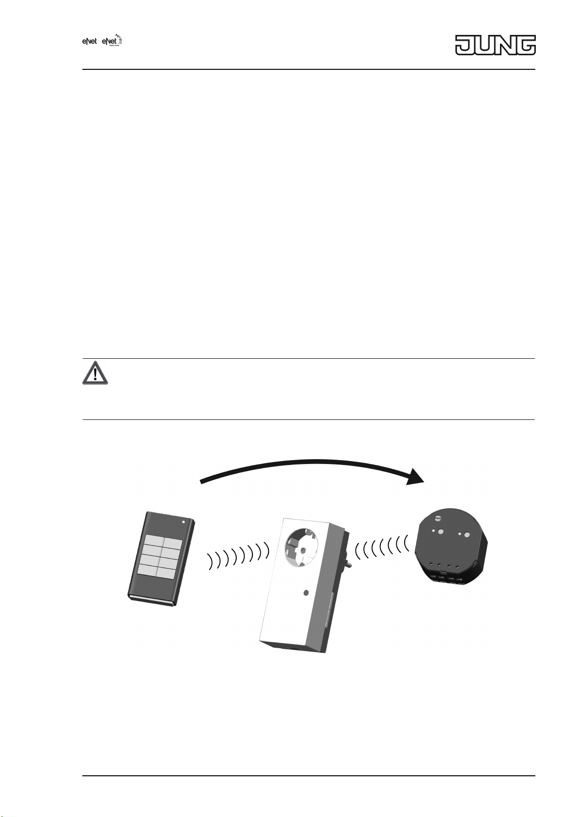
The repeater repeats all radio telegrams.
Figure 2: Direct connection of radio transmitter and actuator
The repeater is in the as-delivered state.
No commissioning of the repeater is necessary.
or
The repeater is connected to an eNet device.
82586533
J0082586533
2/5
27.03.2017
Page 3

eNet radio repeater in SCHUKO housing
o Disconnect all connections or reset repeater to default setting (see Disconnecting
connection to a radio transmitter or actuator or Resetting repeater to default setting).
i Radio transmitters and actuators can be connected to each other as described in the
instructions of the radio transmitters and actuators.
The repeater only repeats radio telegrams from specific devices
Figure 3: Multistage commissioning
If the repeater does not repeat all radio telegrams of a system, multistage commissioning takes
place.
o Step A
Connect repeater to radio transmitter (see Connecting repeater to radio transmitter).
o Step B
Connect repeater to actuator (see Connecting repeater to actuator).
o Step C
Connect radio transmitters and actuators to each other as described in the instructions of
the radio transmitters and actuators.
Two repeaters, switched in sequence, only repeat radio telegrams from certain devices
i If two repeaters are switched in sequence, then connect both the transmitter and the
actuator/energy sensor with both repeaters. During the connection operation, the repeater
and transmitter or actuator/energy sensor must be within radio range of one another.
o Step A
Connect repeaters 1 and 2 to the radio transmitter (see Connecting repeater to radio
transmitter).
o Step B
Connect repeaters 1 and 2 to the actuator (see Connecting repeater to actuator).
o Step C
Connect radio transmitters and actuators to each other as described in the instructions of
the radio transmitters and actuators.
Connecting repeater to radio transmitter
o Press button Prog (3) for longer than 4 seconds.
The status LED (2) flashes after 4 seconds. The repeater is in programming mode for
approx. 1 minute.
o Switch radio transmitter to programming mode (see radio transmitter instructions).
o Trigger telegram on the radio transmitter.
The status LED (2) lights up for 5 seconds.
82586533
J0082586533
3/5
27.03.2017
Page 4

eNet radio repeater in SCHUKO housing
The repeater is connected to the radio transmitter. The repeater and radio transmitter exit
the programming mode automatically.
i The telegrams of all function and scene buttons are repeated by multi-channel radio
transmitters as soon as the first connection is established.
Connecting repeater to actuator or energy sensor
o Press button Prog (3) for longer than 4 seconds.
The status LED (2) flashes after 4 seconds. The repeater is in programming mode for
approx. 1 minute.
o Switch the actuator/energy sensor to programming mode (see actuator/energy sensor
instructions).
o Briefly press Prog button on the repeater to trigger a telegram.
The status LED (2) lights up for 5 seconds.
The repeater is connected to the actuator/energy sensor. The repeater and actuator/energy
sensor exit the programming mode automatically.
i The feedback telegrams of all channels are repeated by multi-channel actuators as soon
as the first connection is established.
Disconnecting connection to a radio transmitter
i All the connections to a radio transmitter are disconnected.
o Carry out the same steps as when connecting (see Connecting repeater to radio
transmitter).
The status LED (2) flashes quickly for 5 seconds. The repeater is disconnected from the
radio transmitter. The repeater and radio transmitter exit the programming mode
automatically.
Disconnecting connection to an actuator or energy sensor
i All the connections to an actuator or energy sensor are disconnected.
o Carry out the same steps as when connecting (see Connecting repeater to actuator or
energy sensor).
The status LED (2) of the repeater and the status LED on the actuator or energy sensor
light up for 5 seconds. The repeater is disconnected from the actuator or energy sensor.
The repeater and actuator/energy sensor exit the programming mode automatically.
Resetting repeater to the default setting
All connections to transmitters and actuators are disconnected and parameters are reset to
default setting.
i The connections in the transmitters and actuators are preserved and must be deleted
separately.
o Press the Prog button for at least 20 seconds.
The status LED flashes after 4 seconds. After 20 seconds the status LED flashes faster.
o Release Prog button and press briefly once again within 10 seconds.
The status LED flashes more slowly for approx. 5 seconds.
The repeater is reset to default setting.
The repeater repeats all received radio telegrams.
5 Appendix
5.1 Technical data
Rated voltage AC 230V~
Mains frequency 50 / 60Hz
Rated load current 16A (IL)
Degree of protection IP 20
Ambient temperature -5 ... +45°C
Dimensions W×H×D 57×127×78 mm
82586533
J0082586533
4/5
27.03.2017
Page 5

eNet radio repeater in SCHUKO housing
Radio frequency 868.0 ... 868.6MHz
Transmitting range in free field typ. 100m
Transmission capacity max. 20mW
Receiver category 2
5.2 Troubleshooting
Additional connections to transmitters or actuators are not possible.
Cause: All the memory locations in the repeater are occupied.
Disconnect connections no longer required.
or
Reset repeater to the default setting so that all received telegrams are repeated.
Despite a repeater there is no radio reception.
Cause 1: Structural conditions prevent radio reception.
Change the position of the repeater.
Cause 2: The repeater only repeats selected telegrams.
Connect radio transmitter and actuator to repeater.
Cause 3: Repeater is not supplied with voltage.
Check power supply.
Cause 4: Two repeaters are switched in sequence. The transmitter and actuator/energy sensor
are not connected to both repeaters.
Connect both the transmitter and the actuator/energy sensor with both repeaters.
Radio transmitter does not receive any feedback from the actuator
Cause: Only the radio transmitter is connected to the repeater.
Connect actuator to repeater.
5.3 Conformity
Albrecht Jung GmbH & Co. KG hereby declares that the radio system type
Art. No. FMR100SGWW
corresponds to the directive 2014/53/EU. You can find the full article number on the device. The
complete text of the EU Declaration of Conformity is available under the Internet address:
www.jung.de/ce
5.4 Warranty
The warranty follows about the specialty store in between the legal framework as provided for
by law.
ALBRECHT JUNG GMBH & CO. KG
Volmestraße 1
58579 Schalksmühle
GERMANY
Telefon: +49 2355 806-0
Telefax: +49 2355 806-204
kundencenter@jung.de
www.jung.de
82586533
J0082586533
5/5
27.03.2017
 Loading...