

Page 1
Radio IP gateway
eNet
Radio IP gateway
Art. No. : FM-GATE-IP
Operating instructions
1 Safety instructions
Electrical equipment may only be installed and fitted by electrically skilled persons.
Serious injuries, fire or property damage possible. Please read and follow manual fully.
The radio communication takes place via a non-exclusively available transmission path,
and is therefore not suitable for safety-related applications, such as emergency stop and
emergency call.
These instructions are an integral part of the product, and must remain with the end
customer.
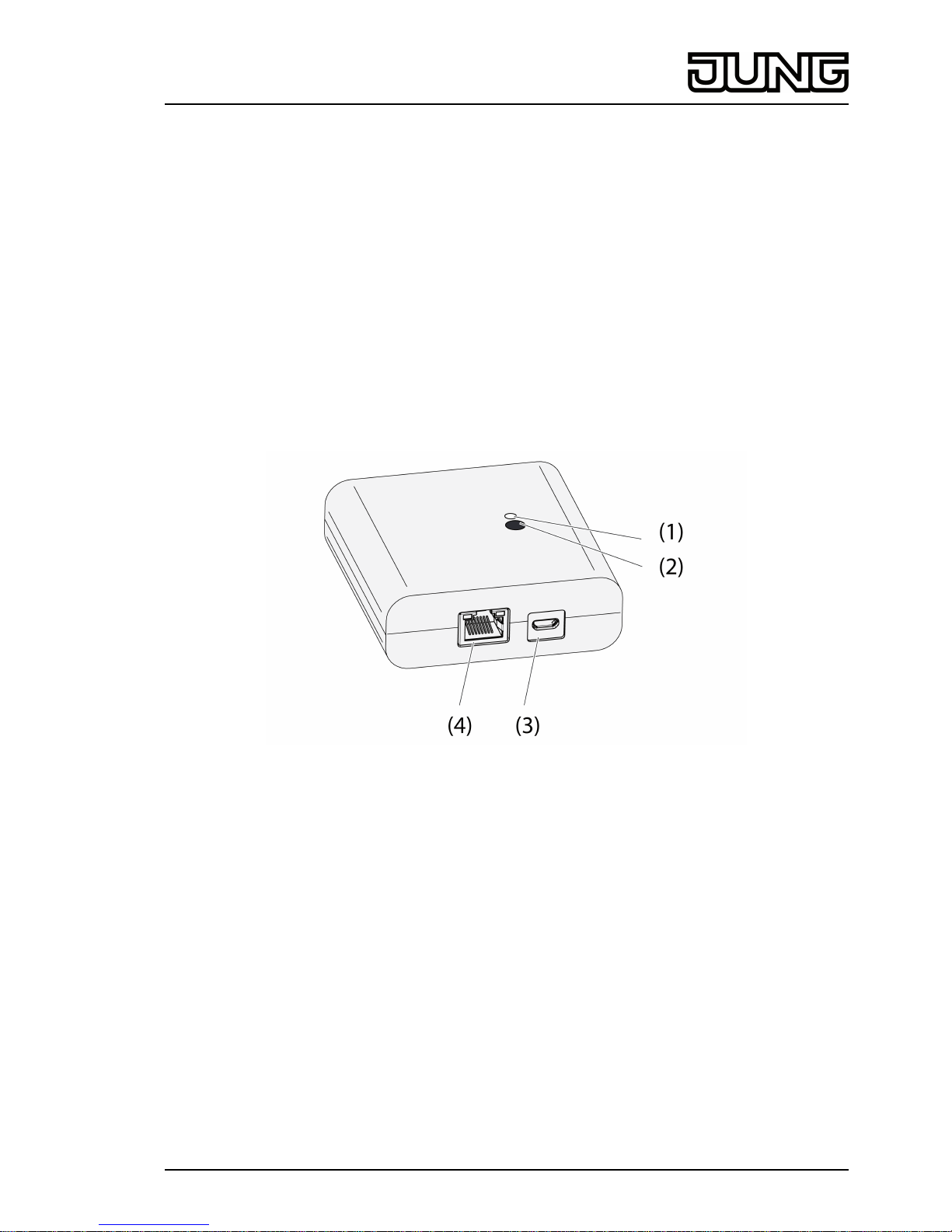
2 Device components
Figure 1: Gateway
(1) Status LED
(2) Button Update/Prog.
(3) USB connection for power supply
(4) Ethernet connection
3 Function
System information
This device is a part of the eNet system.
High transmission reliability at a radio frequency of 868 MHz is achieved by the transmission
behaviour and bidirectional data transfer.
The range of a radio system depends on various external circumstances. The range can be
optimised by the choice of installation location.
This device complies with the requirements of the R&TTE Directive 1999/5/EC. Declaration of
Conformity and further information on the eNet system can be found on our website.
The device may be operated in all EU and EFTA countries.
1/8
82589503
J:0082589503
27.03.2014
Page 2

Legal Notice
This product incorporates open source software components covered by the terms of third party
copyright notices and/or license agreements. Please refer to the attached “License Information”
for details.
Intended use
- Gateway for the operation of eNet switching, dimming and Venetian blind actuators via
tablet PC or smartphone
- Operation with USB power supply
- Operation with WiFi router or access point, which support DHCP (Dynamic Host
Configuration Protocol), or with fixed IP address
- Operation indoors
Product characteristics
- Up to 5 tablet PCs or smartphones can be simultaneously connected to the gateway
- Status LED to display the state of operation
- 20 lists for the compilation of favourite functions
- 24 channels for the operation of eNet actuators
- 16 scenes
- Update of the device software via tablet PC or smartphone
- Wall bracket
- Operation with fixed IP address
Function dependent on the app used:
- All On and All Off
- Lock-out protection for roller shutters or Venetian blinds
- Restraint function
- Master dimming function
Supplementary functions can be activated via eNet server:
- Operation locks
i The parameter list is in the Internet in the documentation for this device.
Supplementary function with eNet server:
- Reading of error memory
Function of status LED (1) in operation
LED turns green Ready for operation
LED flashes green Gateway obtains the IP address from the
router
LED turns green, alternately 5 seconds on and
off
No IP connection available
LED flashes red for 5 seconds Transmission error. The status message of at
least eNet one actuator is missing.
4 Operation
Operation takes place using an app installed on a tablet PC or smartphone. The basic operation
steps are described below. Operation may deviate from this, depending on the app used.
Operating light
o Switching: Press the control surface of the app for less than 0.4 seconds.
o Dimming: Press the control surface of the app for longer than 0.4 seconds. The dimming
process ends when the control surface is released.
Operating blind
o Move Venetian blind: Press the control surface of the app for longer than 1 second.
o Stopping or adjusting the Venetian blind: Press the control surface of the app for less than
1 second.
2/8
82589503
J:0082589503
27.03.2014
eNet
Radio IP gateway
Page 3
Operating push-button actuator
o Press the control surface of the app. The load is switched on for the length of actuation.
i The maximum actuation length is 60 seconds.
Recalling scenes
o Briefly press the control surface of the app.
Actuators switch to the saved scene.
5 Information for electrically skilled persons
5.1 Fitting and electrical connection
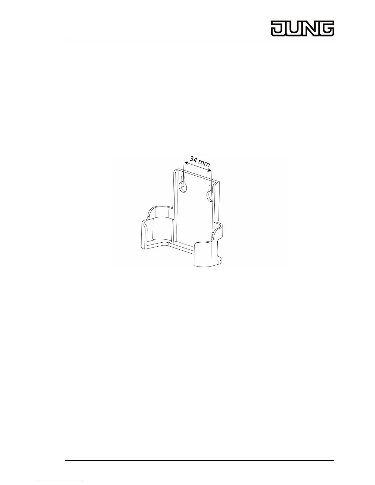
Installing the wall bracket
Figure 2: Hole spacing, wall bracket
To ensure good transmission quality, keep a sufficient distance from any possible sources of
interference, e.g. metallic surfaces, microwave ovens, hi-fi and TV systems, ballasts or
transformers.
o Fasten the wall bracket with countersunk head screws and push the Gateway into the wall
bracket.
3/8
82589503
J:0082589503
27.03.2014
eNet
Radio IP gateway
Page 4

Connect the Gateway
Figure 3: Connection of the Gateway
(4) WiFi router or access point
(5) Gateway
(6) Ethernet cable
(7) USB cable, Micro USB plug.
WiFi route supports DHCP and the Gateway is set up for operation with DHCP (default setting).
o Using the supplied USB cable, connect the Gateway to a free USB connection of the WiFi
router or a USB power supply (not included in the scope of supply).
The Status LED (1) flashes green every 10 seconds (no LAN connection available).
o Establish network connection. To do this, connect the LAN connection to a free LAN
connection of the WiFi router using the Ethernet cable supplied.
The orange LED of the LAN connection lights up when the connection is correct. The green
LED of the LAN connection flashes during data transmission.
The Status LED (1) flashes green, the Gateway is obtaining the IP address of the WiFi
router via DHCP.
The Status LED (1) turns green, meaning the Gateway is ready for operation.
5.2 Commissioning
DANGER!
Electrical shock when live parts are touched.
Electrical shocks can be fatal.
During commissioning, cover the parts carrying voltage on radio transmitters
and actuators and in their surrounding area.
i The Gateway can also be commissioned with eNet server as an alternative to the
commissioning described here.
Connecting a tablet PC or smartphone with the Gateway
o Connect the tablet PC or smartphone with the WiFi router.
o Download the app.
o Launch the app, scan for IP devices and set up the connection.
i The details for connecting the terminal and the Gateway depend on the app used.
4/8
82589503
J:0082589503
27.03.2014
eNet
Radio IP gateway
Page 5

Connecting the Gateway to the actuators
i Up to 10 radio actuators can be connected to a transmitter in a single step.
o Launch the app and select the menu item for commissioning.
o When requested, enter the password (default setting: 0000) to access commissioning.
i For security reasons, change the password after this (see Changing the password).
o Using the app: Select the channel or scene.
o Using the app, switch the Gateway to programming mode.
o Switch the actuator channels to programming mode (see actuator instructions).
The app signals the number of actuators found.
o Confirm the connection in the app.
The channel or scene is connected to the actuators.
Changing the password
o Briefly press the Update/Prog. button (2).
Now, the menu items Commissioning and IP Gateway Settings can be opened for 5
minutes with any password.
o Enter a new password. The password can consist of 1 to 15 numerical characters.
i The new password only becomes valid after 5 minutes.
Update device software
The device software is updated using the app. During the update, only one tablet PC or
smartphone can access the Gateway. Any other tablet PCs or smartphones connected with the
Gateway are informed than an update is taking place.
o Download the new app onto the tablet PC or smartphone.
o Start the update.
o When requested to do so by the app: Press the Update/Prog. button on the Gateway.
After a few seconds, the Status LED (2) will flash green and orange alternately. The device
software is being updated. The flashing rhythm becomes faster during the update.
Status LED is green: Update has been completed. All the tablet PCs or smartphones
connected with the Gateway are informed than the software was updated.
Reset the Gateway to the default setting.
All connections to actuators are disconnected and parameters are reset to default setting.
i The connections in the actuators are preserved and must be deleted separately.
o Press the Update/Prog. button for longer than 20 seconds.
After 20 seconds, the Status LED (1) turns red.
o Release the button and press it briefly once again within 10 seconds.
The status LED turns orange for approx. 15 seconds and then flashes green for approx.
1 second.
The Gateway has been reset to the default setting.
6 Appendix
The icon confirms the conformity of the product to the relevant guidelines.
6.1 Technical data
Rated voltage DC 5 V
Current consumption typical 150 mA
Ambient temperature 0 ... +45 °C
Degree of protection IP 20
Dimensions L×W×H 80×76×25.5 mm
USB connection Micro socket
LAN
5/8
82589503
J:0082589503
27.03.2014
eNet
Radio IP gateway
Page 6

Connection RJ45-socket 8-pin
Radio frequency 868.3 MHz
Transmitting power max. 20 mW
Transmitting range in free field typical 100 m
6.2 Parameter list
Settings window
Device settings
Parameters Setting options, Basic
setting
Explanations
Manual commissioning On, Off
Basic setting: On
Blocks manual commissioning
for all device channels. In the
"Off" setting, the device
cannot be reset to the factory
setting.
Repeater mode On, Off
Basic setting: Off
In addition to its other
functions, the device can be
used as a repeater. In the
"On" setting, the device
repeats all the received
telegrams.
IP address Freely-settable IP address
Basic setting: 192.168.0.23
Setting of the IP address of
the IP Gate.
Subnet mask Freely-settable subnet mask
Basic setting: 255.255.255.0
Setting of the subnet mask.
Standard Gateway Freely-settable IP address
Basic setting: 192.168.0.1
Setting of the Standard
Gateway.
DHCP On, Off
Basic setting: On
Activate the DHCP client.
Automatic allocation of the
network configuration of the
eNet server via a DHCP
(Dynamic Host Configuration
Protocol). When DHCP is
activated, on each switch-on,
the eNet server requests its IP
address from the DHCP
server, along with the subnet
mask, standard gateway and,
if necessary, DNS address.
Settings, channel/scene
Parameters Setting options, Basic
setting
Explanations
Local Operation On, Off
Basic setting: On
With this device, the
parameter has no function.
Manual commissioning On, Off
Basic setting: On
Blocks manual commissioning
for the device channel. In the
"Off" setting, the device
cannot be reset to the factory
setting.
6/8
82589503
J:0082589503
27.03.2014
eNet
Radio IP gateway
Page 7

Sum status / transmission
repetitions
On, Off/Transmit 2x…11x,
Off/Transmit 4x (without
connection)
Basic setting: On
On: The transmitter evaluates
the received status messages
and displays them as an
overall status. If individual
status messages fail, then the
transmitter will repeat its
telegram up to three times.
Off/Transmit ... times: The
evaluation and display of the
overall status is deactivated.
The number of telegram
repetitions is prescribed. In
this setting, no transmission
errors are displayed.
Off/Transmit 4x (without
connection): Reserved for
sensors which transmit without
a connection.
Scene name 1 to 16 Free text, maximum 15
characters
Basic setting: Scene 01 to 16
Name of the scene 1 to 16
Channel name 1 to 24 Free text, maximum 15
characters
Basic setting: Channel 01 to
24
Name of the channel 1 to 24
6.3 Troubleshooting
The status LED (1) flashes green every 10 seconds.
Cause: No LAN connection available.
Check the LAN connection.
Gateway does not obtain the IP address from the router or access point
Cause: Router or access point does not support DHCP.
After approx. 5 minutes, the Gateway switches to the permanent IP address 192.168.0.23
and can then be configured appropriately using the app.
No connection possible between smartphone or tablet PC and the Gateway
Cause: There are already 5 active connections to appropriate devices.
Disconnect any unrequired connections.
Password for access to commissioning forgotten
Before opening the commissioning on the Gateway, press the Update/Prog. button (2)
briefly. When requested to do so by the app, enter the new password.
Additional connections to actuators are not possible.
Cause: all the memory locations in the gateway are occupied.
Disconnect connections no longer required.
or
Use an additional gateway for new connections.
6.4 Accessories
USB charger Art. No. 521-2 USB
iOS App: Apple App Store
Android App: Google Play Store
7/8
82589503
J:0082589503
27.03.2014
eNet
Radio IP gateway
Page 8

6.5 Warranty
We reserve the right to make technical and formal changes to the product in the interest of
technical progress.
We provide a warranty as provided for by law.
Please send the device with a description of the defect to our central customer service office.
ALBRECHT JUNG GMBH & CO. KG
Volmestraße 1
58579 Schalksmühle
Telefon: +49.23 55.8 06-0
Telefax: +49.23 55.8 06-2 04
kundencenter@jung.de
www.jung.de
Service Center
Kupferstr. 17-19
44532 Lünen
Germany
8/8
82589503
J:0082589503
27.03.2014
eNet
Radio IP gateway
 Loading...