

Page 1

eNet motion detector
eNet motion detector
Art. no.: FMDW360WW
Operating instructions
1 Safety instructions
Electrical devices may only be mounted and connected by electrically skilled persons.
Serious injuries, fire or property damage possible. Please read and follow manual fully.
The radio communication takes place via a non-exclusively available transmission path, and is
therefore not suitable for safety-related applications, such as emergency stop and emergency
call.
These instructions are an integral part of the product, and must remain with the end customer.
2 Battery safety instructions
This device or its accessories are supplied with batteries in the form of alkaline batteries LR03.
DANGER! Batteries can be swallowed. This can lead directly to death by suffocation.
Keep new and used batteries away from children.
Do not use devices if the battery compartment does not close securely and keep away from
children.
If you suspect that a battery has been swallowed or is in any orifice of the body, seek immediate
medical attention.
WARNING! Improper handling of batteries can result in explosion, fire or chemical burn due to
leakage.
Do not heat or throw batteries into fire.
Do not reverse polarity, short-circuit or recharge batteries.
Do not deform or disassemble batteries.
Replace batteries only with an identical or equivalent type.
Remove empty batteries immediately and dispose of in an environmentally friendly manner.
Exchange all batteries at the same time. Only use batteries of the same type and manufacturer.
Do not combine old and new batteries.
3 Intended use
– Automatic switching of lighting depending on the heat motion and ambient brightness
– Operation only with radio actuators for switching and dimming from the eNet system
– Ceiling mounting, surface-mounted, in dry interiors
4 Function
Product characteristics
– LED for signalling
– Battery-powered device
– Brightness threshold settable
– Run-on time adjustable
– Sensitivity can be set
Can be set with eNet server:
– Disabling of manual commissioning
– Longer run-on time adjustable
– Brightness threshold settable
– Power saving level
82598403 25.07.2019
J0082598403
1 / 12
Page 2

eNet motion detector
– Transmission behaviour
Supplementary functions with eNet Server
– Fully encrypted radio transmission (AES-CCM)
– Operation with eNet server from version 2.2
– Update of the device software
– Reading of error memory
Automatic operation
The device detects heat motions of people, animals and objects.
– The light is switched on via a connected actuator if a person enters the detection field and
the brightness threshold is below the set brightness threshold.
– The run-on time restarts with each detected motion.
– The light is switched off if no more movement is detected in the detection field and the
run-on time in the actuator has elapsed.
Limiting the switch-on time
If the parameter “Manual switch-off of run-on time” is switched off in the actuator, the light is
switched off after 90 minutes at the latest. This is also the case when there is constant motion in
the detection field. The light is only switched on again if the brightness drops below the
threshold and motions are detected.
If the parameter “Manual switch-off of the run-on time” is activated in the actuator, there is no
limitation.
Display of battery status
After transmission, the status LED (4) (Figure 4) flashes slowly after 3 seconds. The batteries
are almost empty and should be replaced (see chapter “Inserting batteries”).
5 Operation
For manual operation, a radio hand transmitter, for example, must be connected to the radio actuator in addition to the ceiling detector.
The parameter “Manual switch-off of run-on time” is switched off in the actuator (factory setting).
The radio transmitter can be used to make the following settings:
– The actuator can be switched on independently of the brightness for the run-on time
saved in the actuator.
– The run-on time saved in the actuator can be restarted.
– The display brightness can be set in combination with a dimming actuator.
As long as the sensor detects a movement in the detection field, the actuator remains
switched on.
The actuator cannot be switched off.
The parameter “Manual switch-off of the run-on time” is activated with the eNet Server.
The radio transmitter can be used to make the following settings:
– The actuator can be switched on independently of the brightness for the run-on time
saved in the actuator.
– The run-on time saved in the actuator can be restarted.
– The display brightness can be set in combination with a dimming actuator.
As long as the sensor detects a movement in the detection field, the actuator remains
switched on.
– The actuator can be switched off.
If the actuator was switched off manually, automatic switching on of the sensor is locked
for 3 minutes. Any motions that are detected extend the time. Manual switching on via the
radio transmitter is possible at any time.
82598403 25.07.2019
J0082598403
2 / 12
Page 3
eNet motion detector
6 Information for electrically skilled persons
Selecting installation location
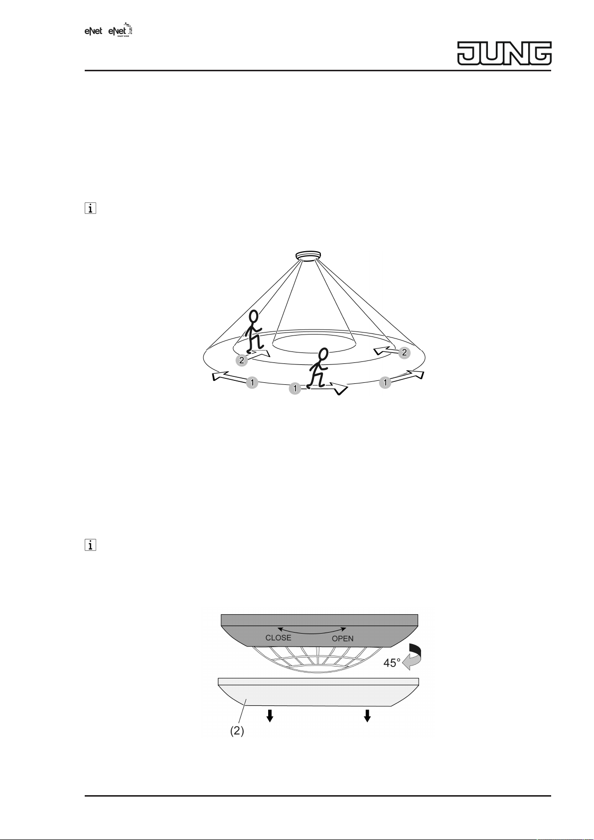
The sensor is installed on the ceiling and monitors the surface below. The sensor has a detection area of 360° and is more sensitive in the central area than in the peripheral area.
The detection of heat sources by a motion detector and thus the extent of the detection field is
influenced by the following criteria: Mounting height, sensitivity setting and direction of movement. Tangential movements can be detected better than radial movements. The range is
therefore greater for tangential movements than for radial movements.
The specifications on the extent of the detection field are general guide values. Discrepancies can occur depending on the installation environment and the intensity of the heat
motion.
Figure1: Detection field
1: Range for tangential movement on the ground is approx. Ø8m (Figure 1)
2: Range for radial movement on the ground is approx. Ø5m (Figure 1)
These specifications refer to mounting on the ceiling at a mounting height of 2.5m. The detection field becomes larger for mounting heights above 2.5m, while the detection density and
sensitivity are reduced at the same time.
■ Select a vibration-free installation location. Vibrations can lead to unwanted switching.
■ Avoid interference sources in the detection area. Interference sources can trigger the mo-
tion detector, e.g. heat sources such as heating units, outlets from ventilation openings or
air conditioners, copiers, printers, coffee machines, draughty doorways, animals etc.
The detection field can be limited in order to minimise the influence of interference
sources. For this, use the push-on cover (see “Limiting the detection field using the pushon cover”).
Fitting the device
Figure2: Disconnect sensor from base plate
82598403 25.07.2019
J0082598403
3 / 12
Page 4
eNet motion detector
Figure3: Fasten the base plate
■ Pay attention to correct alignment of the base plate already during mounting.
■ Align the device so that the brightness sensor (3) (Figure 4) is on the side away from the
windows. This reduces the effects of scattered light.
■ Pull off decor ring (2) (Figure 2).
■ Turn the sensor by approx. 45° in the
OPEN
direction to disconnect it from the base plate
(Figure 2).
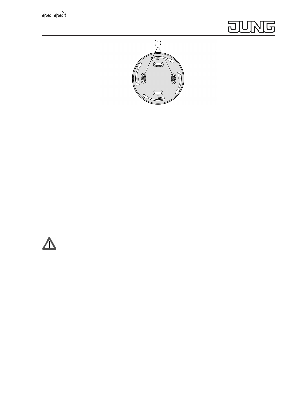
■ Fasten the base plate to the ceiling using screws (1).
■ Perform commissioning.
Expanding the detection field
To expand the detection field, multiple motion detectors can be connected to one actuator. The
devices work independently of each other. Sensitivity, brightness threshold and run-on time are
set for each device. When motion is detected, each motion detector sends a telegram to the actuator. The actuator evaluates the telegrams of the individual motion detectors and switches the
load accordingly. The longest run-on time sent is always executed.
7 Commissioning
DANGER!
Mortal danger of electric shock.
During commissioning, cover the parts carrying voltage on radio transmitters and actuators and in their surrounding area.
Notes on commissioning
– The sensor can also be commissioned with eNet Server as an alternative to the commis-
sioning described here.
– The adjusters (5-7) are located behind the decorative ring (2).
– The light guide (3) for brightness detection is also the
– The status LED (4) is located behind the lens
Test/Prog.
button
82598403 25.07.2019
J0082598403
4 / 12
Page 5

eNet motion detector
Figure4: Adjuster
Without eNet Server the commissioning should be carried out in the following order. This prevents an actuator connected to the sensor from saving an undesired run-on time.
– Set the run-on time on the sensor. The adjuster
Lux
(7) must not be set to PC for a run-on
time of 30min.
– Insert batteries
– Connect sensor to actuator
– Trigger a telegram on the sensor through movement in the detection field
– Perform walking test
– Set sensitivity and brightness threshold
Default settings
In the delivery condition, the adjusters
Time
(6) and
Lux
(7) are in the PC position. The sensor
can only be programmed with the eNet server if both adjusters are set to PC. Values for the runon time and the brightness threshold are preset at the factory.
As soon as one of the two adjusters is shifted from position PC and a telegram is subsequently triggered, the sensor operates with the currently set values.
Adjuster Position Value
Sens.
Time
Lux
(7)
(5)
(6)
max
PC
PC
100%
2 min
2000 lx
Insert batteries
Obey the battery safety instructions.
If the sensor is to be operated with the factory settings, the adjusters
Time
(6) and
Lux
(7)
(Figure 4) must be in position PC before inserting the batteries. If this is not the case, the
values for the run-on time and the brightness threshold are replaced by the values
entered at the adjusters. To use the values of the factory setting again, the sensor must
be reset to the factory setting (see chapter “Resetting the sensor to factory setting”).
82598403 25.07.2019
J0082598403
5 / 12
Page 6

eNet motion detector
Figure5: Insert batteries
■ Pull off decor ring (2).
■ Turn the sensor by approx. 45° in the
OPEN
direction to disconnect it from the base plate
(Figure 2).
■ Insert batteries with correct polarity (Figure 5).
The status LED (4) lights up for 1 minute. The sensor performs a self-test. No movements
are recorded during this time.
■ Place the sensor on the base plate and turn it by approx. 45° in the
CLOSE
direction until
the sensor audibly engages.
■ Attach decor ring (2).
Setting the sensitivity
The sensitivity cannot be set via the eNet Server.
■ Turn adjuster
Sens.
(5) (Figure 4) in
max
direction for higher sensitivity or in
min
direction
for lower sensitivity.
Set run-on time
The run-on time is set between approx. 10seconds and 30minutes using adjuster
Time
(6).
The run-on time can be set between 10seconds and 60minutes using eNet server.
The actuator saves the first run-on time received. The actuator uses it for every switch-on
command of a transmitter, e.g. of a wall transmitter that does not transmit its own run-on
time. The run-on time saved in an actuator can only be subsequently changed with the
eNet Server or after a factory reset of the actuator.
■ Turn adjuster
Time
(6) (Figure 4) to the desired value.
Setting the brightness threshold
The brightness value measured at the sensor corresponds to the brightness below the installation location. If the current brightness value is to be set as the brightness threshold, it is recommended to activate the walking test and then to slowly turn the adjuster
Lux
(7). The status LED
(3) indicates for each detected movement whether the brightness threshold is exceeded or not
reached (see Testing detection field).
■ Turn adjuster
Lux
(7) (Figure 4) to the desired value.
Icon Brightness threshold
2 approx. 5lx
ư approx. 150lx*
3 Brightness-independent – day operation
* Setting for stairways according to DIN EN12464-1, 2003-03
Resetting sensor to factory setting
The connections to the actuators and to the eNet Server are disconnected and parameters are
reset to the factory setting.
82598403 25.07.2019
J0082598403
6 / 12
Page 7

eNet motion detector
The connections in the actuators and eNet Server are preserved and must be deleted
separately.
■ Turn adjuster
■ Press the
Prog.
Time
(6) and
(3) button (Figure 4) for longer than 20seconds.
Lux
(7) (Figure 4) to
PC
position.
The status LED (4) flashes after 4 seconds. The status LED (4) flashes faster after
20seconds.
■ Release the button and press it briefly once again.
The status LED (4) flashes more slowly for approx. 5seconds.
The sensor is reset to the factory setting.
If adjusters
Time
(6) and
Lux
(7) have not been turned to the PC position, the values for
the follow-up time and the brightness threshold are taken over by the adjusters.
Connecting to radio actuator
Up to 10 radio actuators can be connected to a transmitter in a single step.
■ Switch the actuator to programming mode (see actuator instructions).
■ Press the
Prog.
(3) button (Figure 4) for longer than 4 Sekunden.
Status LED (4) (Figure 4) flashes. The sensor is in programming mode for approx.
1minute.
■ Press button
Prog.
(3) briefly.
The status LED of the actuator lights up for approx. 5seconds. The sensor is connected
to the actuator. The sensor and actuator exit the programming mode automatically.
If the status LED of sensor (4) flashes 3 times at 1-second intervals for approx.
5 seconds, then the programming procedure was not successful. The actuator is outside
radio range, not in programming mode or there are radio faults.
If the status LED of the actuator flashes 3 times at 1-second intervals for approx.
5 seconds, then the programming procedure was not successful. All memory locations in
the actuator or sensor are occupied.
Press the
Prog.
button once again for longer than 4seconds to terminate the program-
ming mode prematurely.
Disconnecting connection to an actuator
■ Carry out the same steps as when connecting (see the chapter Connecting to radio actu-
ator).
The status LED of the actuator flashes quickly for 5 seconds. The actuator is disconnec-
ted from the sensor. The sensor and actuator exit the programming mode automatically.
Testing the detection field
The walking test should not be started until the connected actuators have received at
least one telegram with the desired settings for the run-on time from the sensor. If this is
not the case, the actuators save the 1-second run-on time of the walking test.
If the sensor detects movement during the walking test, it switches on the connected actuator for approx. 1 second. If the brightness threshold is not reached, the status LED (3)
(Figure 4) lights up for approx. 1 second. If the brightness threshold is exceeded, the
status LED (3) flashes quickly for approx. 1 second. In order for the shortened run-on time
of 1s to be effective in the actuator during the walking test, a longer run-on time must not
be active in the actuator when the walking test is activated. Ideally, the walking test is activated when the actuator is switched off.
■ To activate the walking test: Press
Prog
button (3) (Figure 4) for less than 1second.
■ Pace off the detection field, paying attention to reliable detection and interference
sources. If necessary, limit the detection field by using the push-on cover or reduce the
sensitivity with adjuster
■ If required, adjust the brightness threshold with adjuster
82598403 25.07.2019
J0082598403
Sens.
.
Lux
.
7 / 12
Page 8

eNet motion detector
■ To exit the walking test: Press
Prog
button (3) briefly or wait for approx. 5minutes.
Limiting the detection field using the push-on cover
The push-on cover can be used to limit the detection field, e.g. in order to mask out interference
sources.
Figure6: Push-on cover
Size Tangential detection field (mounting height
2.5m)
Complete push-on cover Ø approx. 2.2 m
Area I cut out Ø approx. 4.0 m
Areas I + II cut out Ø approx. 6.0 m
without push-on cover Ø approx. 8.0 m
■ Pull off push-on cover.
■ Using scissors, cut out push-on cover along the marked lines as required.
■ Push on push-on cover.
The detection field can alternatively be limited by reducing the sensitivity.
8 Disposal of batteries
Remove empty batteries immediately and dispose of in an environmentally friendly
manner. Do not throw batteries into household waste. Consult your local authorities
about environmentally friendly disposal. According to statutory provisions, the end
consumer is obligated to return used batteries.
9 Technical data
Rated voltage DC 6 V
Battery type 4×alkaline LR 03
82598403 25.07.2019
J0082598403
8 / 12
Page 9

eNet motion detector
Ambient temperature -5 ... +45 °C
Degree of protection IP20
Brightness setting approx. 5 ... 2000lx (and day opera-
tion)
Sensitivity 25 ... 100%
Run-on time approx. 10 s ... 30min (60min with
eNet Server)
Installation height 2.5 m
Detection angle 360°
Detection field
Radial Ø approx. 5 m
Tangential Ø approx. 8 m
Dimensions Ø×H 103 × 42 mm
Transmitting range in free field typ. 100 m
Radio frequency 868.0 ... 868.6 MHz
Transmission capacity max. 20 mW
Receiver category 2
10 Parameter list
The device parameters can be changed with the eNet server:
Device and channels
Parameter name Setting options, Basic setting Explanations
Function Motion detection, not used
Default setting: Motion detection
Advanced device settings
Parameter name Setting options, Basic setting Explanations
Manual commissioning On, Off
Basic setting: On
Motion detection
The channel works as a motion detector
Unused
The channel is not displayed
eNet SMART HOME
in the
app
and is disabled for use in
the commissioning interface.
Disables manual commissioning for all device channels. In
the "Off" setting, the device
cannot be reset to the factory
setting.
Channel settings
Parameter name Setting options, Basic setting Explanations
Brightness evaluation On, Off
Basic setting: On
On
The currently measured
brightness value is also taken
into account during each motion detection.
Off
The current brightness value
82598403 25.07.2019
J0082598403
9 / 12
Page 10

eNet motion detector
Parameter name Setting options, Basic setting Explanations
is ignored and the device
works brightness-independent
(day operation).
This setting does not affect
the transmission of brightness
values to the eNet Server for
use in the
HOME app
eNet SMART
Brightness threshold 5 ... 2000 lx
Basic setting 2000lx
A motion signal is evaluated
below the set brightness
threshold. This only applies to
the first detection of a movement (light is not yet switched
on).
Run-on time 10 s ... 60 min
Basic setting: 2 min
The sensor transmits the set
run-on time during each motion detection. Connected actuators remain switched on for
this time. Should proprietary
run-on times be set in the actuators, then they will be ignored.
Extended channel settings
Parameter name Setting options, Basic setting Explanations
Manual commissioning On, Off
Basic setting: On
Blocks manual commissioning
for the device channel. In the
"Off" setting, the device cannot be reset to the factory setting.
Local Operation On, Off
Basic setting: On
Blocks the device channel for
local operation. With this
device, the parameter has no
function.
Power saving level Low, Medium, High
Basic setting: Low
Extends battery life by reducing measurements and transmissions in locations with frequent movement.
The power saving level should
be set to High in areas with
frequent movement (maximum
idle time).
The power saving level should
be set to Medium in areas with
limited movement and a short
run-on time (ranging from
seconds to a few minutes)
(medium idle time).
The power saving level can be
set to Low in areas with limited movement and a long runon time (minimum idle time).
82598403 25.07.2019
J0082598403
10 / 12
Page 11

eNet motion detector
Parameter name Setting options, Basic setting Explanations
Transmission behaviour Do not send brightness val-
ues / power-optimised
Do not send brightness values / power-optimised
Send brightness values automatically / power-optimised
Send brightness values automatically / information-optimised
Basic setting: Send brightness
values automatically / poweroptimised
Power-optimised:
If movements are constantly
detected, the device sends a
telegram after 3 minutes at the
latest. This setting should be
selected if the telegrams are
not used by the eNet Server.
Information-optimised:
If movements are constantly
detected, the device sends a
telegram after 1 minute at the
latest. This setting should be
selected if the telegrams are
used by the eNet Server, e.g.
to control functions.
Do not send brightness values:
The device does not send any
brightness values.
Send brightness values automatically:
The device sends the measured brightness values. Der
eNet Server can use these to
e.g. control brightness-dependent functions.
11 Troubleshooting
Actuator does not switch on
Cause 1: The ambient brightness is greater than the brightness threshold set on the sensor.
Set brightness threshold.
Cause 2: Sensor does not detect any motion.
Increase sensitivity.
Check the push-on cover.
Cause 3: Actuator does not receive any telegrams from the sensor.
Check radio reception.
Cause 4: Sensor and actuator are not connected.
Connect sensor to actuator (see chapter Connecting to radio actuator).
Cause 5: The actuator was switched off manually with a radio transmitter (see chapter Operation).
– Switch on actuator with radio transmitter manually.
– Ensure that there is no motion in the detection field for 3 minutes.
Actuator switches on without any motion
Cause 1: Interference sources in the detection field.
Remove interference sources if possible.
Reduce sensitivity.
Limit the detection field using the push-on cover.
82598403 25.07.2019
J0082598403
11 / 12
Page 12

eNet motion detector
Cause 2: The actuator is connected with a radio transmitter which was used for manual switching on.
Actuator switches off despite motion
Cause 1: Sensor does not detect any motion.
Increase sensitivity.
Cause 2: Detection area is limited by push-on cover.
Check the push-on cover.
Cause 3: The parameter “Manual switch-off of run-on time” is switched off in the actuator. The
actuator switches off after 90 minutes, even if the sensor still detects motion.
Actuator does not switch off
Cause 1: Interference sources in the detection field, sensor detects motion constantly.
Remove interference sources if possible.
Reduce sensitivity.
Limit the detection field using the push-on cover.
12 Conformity
Albrecht Jung GmbH & Co. KG hereby declares that the radio system type art. no. FMDW360WW meets the directive 2014/53/EU. You can find the full article number on the device.
The complete text of the EU Declaration of Conformity is available under the Internet address:
www.jung.de/ce
13 Warranty
The warranty is provided in accordance with statutory requirements via the specialist trade.
ALBRECHT JUNG GMBH & CO. KG
Volmestraße 1
58579 Schalksmühle
GERMANY
Telefon: +49 2355 806-0
Telefax: +49 2355 806-204
kundencenter@jung.de
www.jung.de
82598403 25.07.2019
J0082598403
12 / 12
 Loading...