

Page 1
Radio transmitter modules
eNet
Radio transmitter module 1-channel
Art. No. : FM 4001 M
Radio transmitter module 2-channel
Art. No. : FM 4002 M
Radio transmitter module 3-channel
Art. No. : FM 4003 M
Radio transmitter module 4-channel
Art. No. : FM 4004 M
Operating instructions
1 Safety instructions
Electrical equipment may only be installed and fitted by electrically skilled persons.
Keep button cells out of reach of children! If button cells are swallowed, get medical help
immediately.
Risk of explosion! Do not throw batteries into fire.
Risk of explosion! Do not recharge batteries.
The radio communication takes place via a non-exclusively available transmission path,
and is therefore not suitable for safety-related applications, such as emergency stop and
emergency call.
These instructions are an integral part of the product, and must remain with the end
customer.
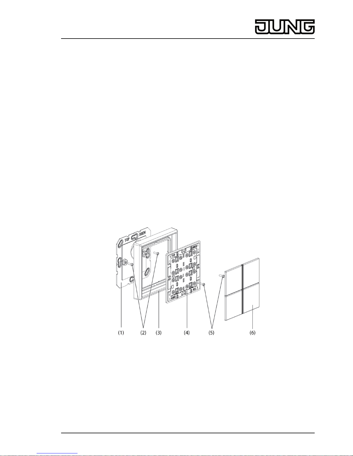
2 Device components
Figure 1: 4-gang radio wall transmitter module
(1) Base plate
(2) Fastening screws
(3) Design frame
(4) Wall transmitter module
(5) Plastic screws
(6) Covers
1/10
32579203
J:0082579203
20.03.2014
Page 2

3 Function
System information
This device is a part of the eNet system.
High transmission reliability at a radio frequency of 868 MHz is achieved by the transmission
behaviour and bidirectional data transfer.
The range of a radio system depends on various external circumstances. The range can be
optimised by the choice of installation location.
This device complies with the requirements of the R&TTE Directive 1999/5/EC. Declaration of
Conformity and further information on the eNet system can be found on our website.
The device may be operated in all EU and EFTA countries.
Intended use
- Radio sensor for transmission of switching, dimming, blind movement and scene
commands
- Operation with radio actuators from the eNet system
Product characteristics
- Display of the actuator status for status poll by a green LED per channel
- Display of the transmission status by a red LED
- Switch-on brightness of dimmer actuators can be saved.
- Battery-powered device
- Signalling of transmission errors can be switched off
Can be set with eNet server:
- Master dimming function
- Scene All On
- Operation locks
i If settings are changed with the eNet server, operation and signalling could vary from what
is described here.
i The parameter list is in the Internet in the documentation for this device.
Supplementary function with eNet server
- Update of the device software
4 Operation
Function of status LED in operation
As soon as a button is pressed or released, the status LED first signals radio transmission
- LED turns red for 2 seconds
and then the actuator status/group status
- LED turns green for 3 seconds:
At least one actuator is switched on, or one Venetian blind is not in the top end position
- LED remains off:
All the actuators are switched off or the blinds are all in the upper end position
or - if there is no status message from an actuator - a transmission error.
- The LED rapidly flashes red for 5 seconds:
The status message of at least one actuator is missing
2/10
32579203
J:0082579203
20.03.2014
eNet
Radio transmitter modules
Page 3
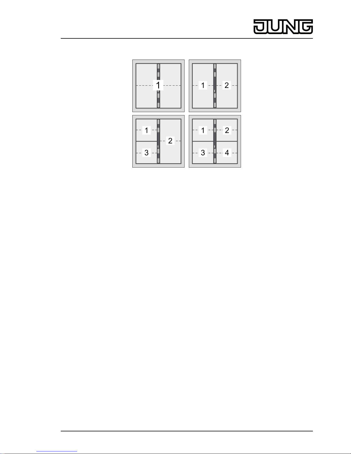
Channel assignment of the wall transmitter
Figure 2: Channel assignment of wall transmitter module 1-gang, 2-gang, 3-gang and 4-gang
Operating light
o Switching: Press button for less than 0.4 seconds.
o Dimming: Press the button for longer than 0.4 seconds. The dimming process ends when
the button is released.
o Switching on dimmer actuators at minimum brightness: Press the bottom button for longer
than 0.4 seconds.
o Switching on dimmer actuators at minimum brightness and dimming to maximum
brightness: Press the top button for longer than 0.4 seconds.
Operating blind
o Moving the Venetian blind: Press the button for longer than 1 second.
o Stopping or adjusting the Venetian blind: Press the button for less than 1 second.
Operating push-button actuator
o Buttons: The load is switched on for the duration of the button-press.
i The maximum actuation length is 60 seconds.
Recalling scenes
o Press the scene button briefly.
Actuators switch to the saved scene.
Changing scene
o Press the scene button briefly.
Actuators switch to the saved scene.
o Setting a new scene.
o Press scene button for longer than 4 seconds.
Actuators first switch to the old scene and save the new scene after 4 seconds.
Save switch-on brightness
The buttons of a channel are set as channel buttons.
With dimmer actuators a brightness value can be saved to which the dimmer actuator switches
after a short button press.
3/10
32579203
J:0082579203
20.03.2014
eNet
Radio transmitter modules
Page 4

o Set required switch-on brightness.
o Press button over entire surface for longer than 4 seconds.
The light is briefly switched off and switched on again to the switch-on brightness. Switchon brightness is saved.
Polling sum status
The buttons of a channel are set as channel buttons.
i Polling is not possible with scene buttons.
o Press button over entire surface for 1 to 4 seconds.
Signalling of radio transmission and group status (see function of the status LED in
operation)
5 Information for electrically skilled persons
5.1 Fitting and electrical connection
Fitting the device
To ensure good transmission quality, keep a sufficient distance from any possible sources of
interference, e.g. metallic surfaces, microwave ovens, hi-fi and TV systems, ballasts or
transformers.
i Perform commissioning procedures before installation (see chapter Commissioning).
o Carefully remove covers (6) from wall transmitter (figure 1).
o Remove wall transmitter module (4) from the base plate (1).
o Changing the battery (see chapter Changing the battery).
o Glue or screw the base plate to an even surface. The TOP/OBEN label has to be at the
top.
o Attach design-frame (3) to the base plate.
o Screw wall transmitter module to base plate.
i Screwing the screws too tightly could impair functions of the wall transmitter.
o Snap covers on.
Information on gluing mounting
To be able to fasten the wall transmitter safely, the substrate must be flat and free of dust and
grease.
o Remove the rear, unpunched film of the enclosed adhesive pad.
o Align the adhesive pad, stick it to the surface and smooth it out. Remove air bubbles.
o Remove the two inner segments of the front film.
o Align the base plate to the external punching and stick it on.
i In the case of multiple combinations, the abutting sides of the adhesive pads must be cut
along the external punching using a ruler and a cutter (figure 3).
4/10
32579203
J:0082579203
20.03.2014
eNet
Radio transmitter modules
Page 5

Figure 3: Cutting the adhesive pads for multiple combinations
i If necessary, after mounting the wall transmitter in the CD program, carefully remove the
excess adhesive film in the corners.
5.2 Commissioning
Insert battery
WARNING!
Risk of chemical burns.
Batteries can burst and leak.
Replace batteries only with an identical or equivalent type.
o Unscrew wall transmitter from the base plate (see Mounting the device).
i Keep contacts of batteries and device free of grease.
o Apply battery to the positive contact of the battery holder. Observe polarity: the positive
pole of the battery must be at the top.
o Press gently on battery to snap it in.
o Mount wall transmitter on the base plate.
The wall transmitter is ready for operation.
DANGER!
Electrical shock when live parts are touched.
Electrical shocks can be fatal.
During commissioning, cover the parts carrying voltage on radio transmitters
and actuators and in their surrounding area.
Connecting channel button to radio actuator
i Up to 10 radio actuators can be connected to a transmitter in a single step.
i If the programming mode cannot be activated while the cover is snapped on, the cover
must be removed.
5/10
32579203
J:0082579203
20.03.2014
eNet
Radio transmitter modules
Page 6

Figure 4: Activating programming mode for channel buttons
o Press the top left and bottom right buttons simultaneously for longer than 4 seconds
(figure 4).
Red LED flashes slowly. The radio sensor is in programming mode for approx. 1 minute.
o Switch the actuator to programming mode (see actuator instructions).
o Press the required channel button at the top briefly.
The button is configured as channel button and connected to the actuator. The red LED
lights up for approx. 5 seconds. The radio sensor and the actuator exit the programming
mode automatically.
i If the red LED of the radio transmitter flashes 3 times at 1-second intervals for approx.
5 seconds, then the programming operation was not successful. The actuator is outside
radio range, not in programming mode or there are radio faults.
i If the status LED of the actuator flashes 3 times at 1-second intervals for approx.
5 seconds, then the programming operation was not successful. All the memory locations
in the actuator or radio transmitter are occupied.
i Press the top left and bottom right button once again simultaneously for longer than 4
seconds to terminate the programming mode earlier.
i The All Off button of a radio transmitter is connected to the actuator automatically as soon
as the first connection to a radio transmitter takes place. Scene buttons must be connected
separately.
Connecting scene button to radio actuator
i If the programming mode cannot be activated while the cover is snapped on, the cover
must be removed.
The buttons of the wall transmitter are preallocated with the following scenes:
Buttons Button allocation
1 top / 1 bottom Scene 1 / All Off
2 top / 2 bottom Scenes 2 / Scene 3
3 top / 3 bottom Scenes 4 / Scene 5
4 top / 4 bottom Scenes 6 / Scene 7
6/10
32579203
J:0082579203
20.03.2014
eNet
Radio transmitter modules
Page 7

Figure 5: Activating programming mode for scene buttons
o Press the top right and bottom left buttons simultaneously for 4 seconds (figure 5).
The red LED flashes slowly. The function sensor is in programming mode.
o Switch radio actuator to programming mode (see radio actuator instructions).
o Press the scene button briefly.
The button is configured as scene button and connected to the actuator. The red LED
lights up for approx. 5 seconds. The programming mode is exited automatically.
i If the red LED on the radio transmitter flashes 3 times at 1-second intervals for approx.
5 seconds, then the programming operation was not successful. The actuator is outside
radio range, not in programming mode or there are radio faults.
i If the status LED of the actuator flashes 3 times at 1-second intervals for approx. 3
seconds, then the programming operation was not successful because all memory
locations in the actuator or radio transmitter are occupied.
i Press the top right and bottom left button once again simultaneously for longer than 4
seconds to terminate the programming mode earlier.
Disconnecting connection to an actuator
o Carry out the same steps as when connecting (see the chapter Connecting channel button
to radio actuator).
The status LED of the actuator flashes quickly for 5 seconds. The actuator is disconnected
from the radio transmitter. The actuator and radio transmitter exit the programming mode
automatically.
i If there several connections or scene buttons for an actuator, all the connections must be
disconnected individually.
i All On and All Off buttons of a radio transmitter are disconnected automatically as soon as
the last connection to the actuator is disconnected. Manual disconnection is not possible.
Polling button programming
o Briefly press the top right and bottom left buttons simultaneously, see (figure 5).
All functions are terminated.
Permanent lighting of the green LED for programming as channel button.
Rapid flashing of the green LED for programming as scene button.
Resetting the channel or scene button
The connections to the actuators are disconnected and parameters are reset to default setting.
i The connections in the actuators are preserved and must be deleted separately.
7/10
32579203
J:0082579203
20.03.2014
eNet
Radio transmitter modules
Page 8

o Press the top left and bottom right buttons simultaneously for longer than 20 seconds
(figure 4).
The red status LED flashes after 4 seconds. After 20 seconds the LED flashes faster.
o Press the desired button briefly.
The red LED flashes more slowly.
The channel button or scene button has been reset. The setting as channel button or
scene button is retained.
Resetting wall transmitter to the default setting
All connections to the actuators are disconnected and parameters are reset to default setting.
i The connections in the actuators are preserved and must be deleted separately.
o Press the top left and bottom right buttons simultaneously for longer than 20 seconds
(figure 4).
The red status LED flashes after 4 seconds. After 20 seconds the LED flashes faster.
o Release buttons and press the top left and bottom right buttons simultaneously once again.
The red LED flashes more slowly for approx. 5 seconds.
The wall transmitter is reset to default setting. All the buttons are set as channel buttons.
6 Appendix
Remove empty batteries immediately and dispose of in an environmentally friendly
manner. Do not throw batteries into household waste. Consult your local authorities
about environmentally friendly disposal. According to statutory provisions, the end
consumer is obligated to return used batteries.
The icon confirms the conformity of the product to the relevant guidelines.
6.1 Technical data
Rated voltage DC 3 V
Battery type 1×Lithium CR 2450N
Ambient temperature -5 ... +45 °C
Degree of protection IP 20
Transmitting range in free field typical 100 m
Radio frequency 868.3 MHz
Transmitting power max. 20 mW
6.2 Parameter list
Settings window
Device settings
Parameter name Setting options, Basic
setting
Explanations
Manual commissioning On, Off
Basic setting: On
Blocks manual commissioning
for all device channels. In the
"Off" setting, the device
cannot be reset to the factory
setting.
Channel 1 Rocker switch, scene
Basic setting: Rocker switch
Setting the buttons of the
channel as channel buttons
(rocker switch) or scene
buttons (scene).
Channel 2 * Rocker switch, scene
Basic setting: Rocker switch
Setting the buttons of the
channel as channel buttons
(rocker switch) or scene
buttons (scene).
8/10
32579203
J:0082579203
20.03.2014
eNet
Radio transmitter modules
Page 9

Channel 3 * Rocker switch, scene
Basic setting: Rocker switch
Setting the buttons of the
channel as channel buttons
(rocker switch) or scene
buttons (scene).
Channel 4 * Rocker switch, scene
Basic setting: Rocker switch
Setting the buttons of the
channel as channel buttons
(rocker switch) or scene
buttons (scene).
Settings, channel/scene
Parameter name Setting options, Basic
setting
Explanations
Local Operation On, Off
Basic setting: On
Blocks the device channel for
local operation.
Manual commissioning On, Off
Basic setting: On
Blocks manual commissioning
for the device channel. In the
"Off" setting, the device
cannot be reset to the factory
setting.
Sum status / transmission
repetitions
On, Off/Transmit 2x…11x,
Off/Transmit 4x (without
connection)
Basic setting: On
On: The transmitter evaluates
the received status messages
and displays them as an
overall status. If individual
status messages fail, then the
transmitter will repeat its
telegram up to three times.
Off/Transmit ... times: The
evaluation and display of the
overall status is deactivated.
The number of telegram
repetitions is prescribed. In
this setting, no transmission
errors are displayed.
Off/Transmit 4x (without
connection): Reserved for
sensors which transmit without
a connection.
* Channel 2 to 4 only for multi-channel wall transmitters
6.3 Troubleshooting
After a brief button-press, the red LED flashes five times.
Cause: battery in the wall transmitter is almost empty.
Change the battery (see chapter Changing the battery).
Receiver does not react, status LED displays a transmission error. Status LED flashes
quickly for approx. 5 seconds.
Cause 1: Radio range exceeded. Structural obstacles reduce the range.
Using a radio repeater.
Cause 2: Actuator is not ready for operation.
Check the actuator and mains voltage.
Cause 3: There are radio faults, e.g. through outside radio.
Eliminate radio interference.
9/10
32579203
J:0082579203
20.03.2014
eNet
Radio transmitter modules
Page 10

i The actuator causing the transmission error can be removed from the display of
transmission errors. To do this, briefly press the top left and bottom right buttons of the wall
transmitter simultaneously during the signalling. The LED lights up red. During this time, do
not press any button on the wall transmitter. The actuator is automatically taken into
account again when it transmits a status message after radio transmission.
6.4 Accessories
Cover kit 1-gang, complete Art. No. ..401 TSA..
Cover kit 2-gang, complete Art. No. ..402 TSA..
Cover kit 3-gang, complete Art. No. ..403 TSA..
Cover kit 4-gang, complete Art. No. ..404 TSA..
6.5 Warranty
We reserve the right to make technical and formal changes to the product in the interest of
technical progress.
We provide a warranty as provided for by law.
Please send the device with a description of the defect to our central customer service office.
ALBRECHT JUNG GMBH & CO. KG
Volmestraße 1
58579 Schalksmühle
Telefon: +49.23 55.8 06-0
Telefax: +49.23 55.8 06-2 04
kundencenter@jung.de
www.jung.de
Service Center
Kupferstr. 17-19
44532 Lünen
Germany
10/10
32579203
J:0082579203
20.03.2014
eNet
Radio transmitter modules
 Loading...