

Page 1
EnOcean EnOcean radio wall transmitter
Ref.-no.: ENO..590.., ENO..990..,
ENO..595.., ENO..995..
Operating Instructions
EnOcean radio wall transmitter
1. Safety instructions
Electrical devices may only be installed and fitted by electrically
skilled persons.
Non-compliance with the instructions could cause damage to the
device, fire or other hazards.
The radio transmission takes place over a nonexclusively available
transmission path, and is therefore not suitable for applications in
the field of safety technology, such as emergency stop and
emergency call.
These instructions are a component part of the product and must
remain with the end customer.
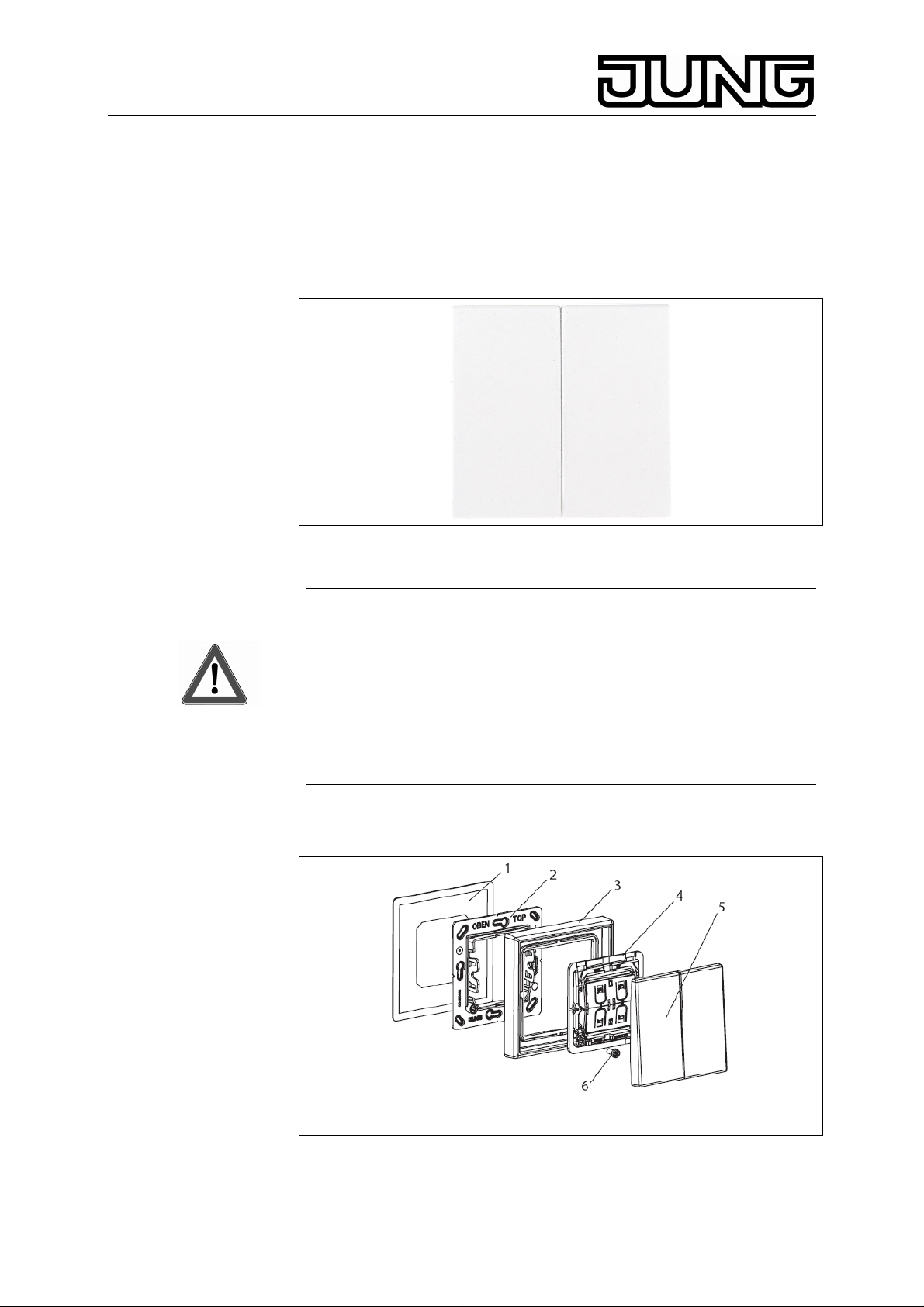
2. Structure of the device
Stand: Jul-10 325 270 03
Figure 1: Structure of the device
(1) Adhesive foil (4) EnOcean module
(2) Holder plate (5) Rocker
(3) Frame (6) Locking screw
Page 2
EnOcean EnOcean radio wall transmitter
Ref.-no.: ENO..590.., ENO..990..,
ENO..595.., ENO..995..
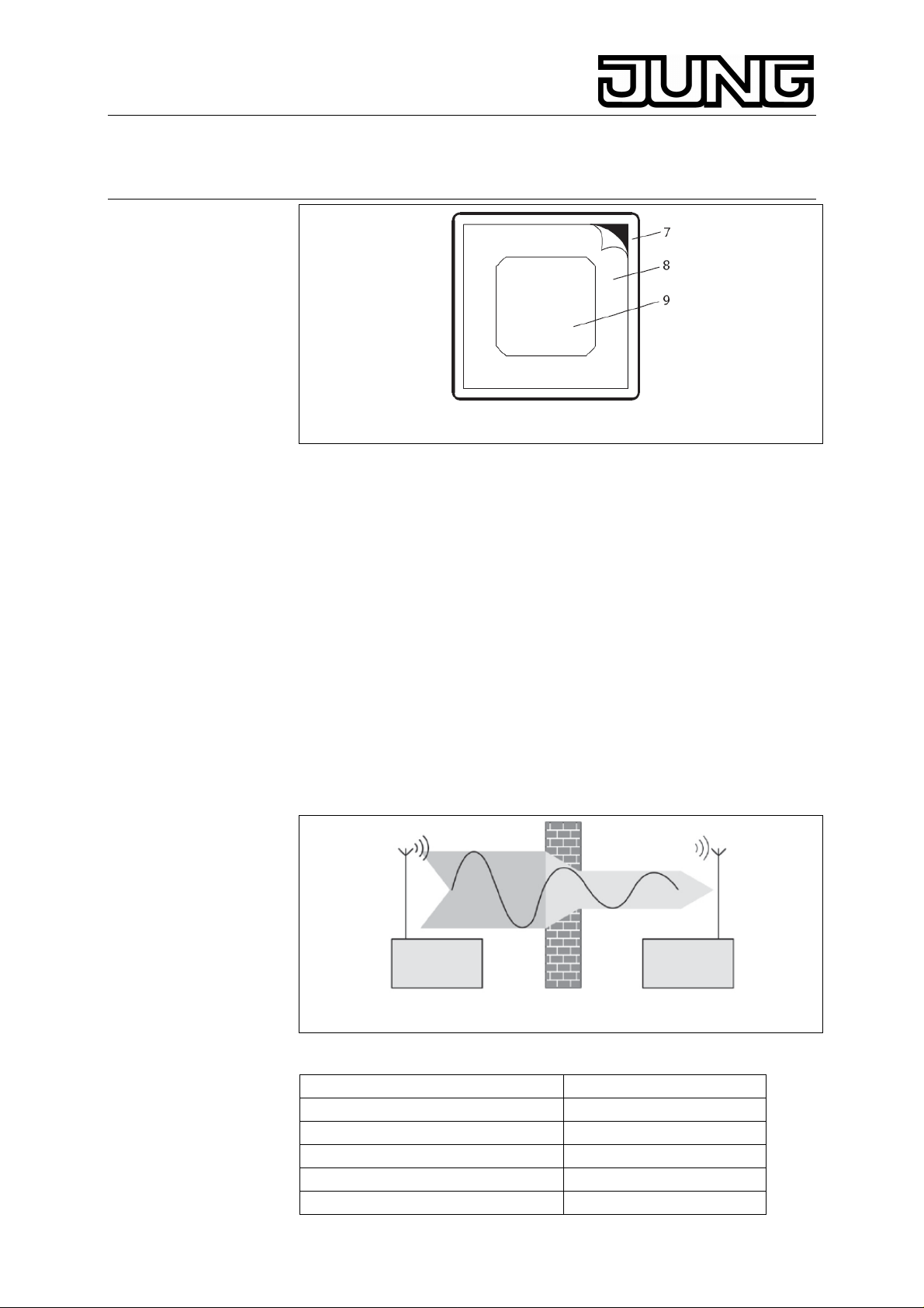
Figure 2: Adhesive foil
(7) Protective foil for frame
(8) Protective foil for holder plate
(9) Protective foil for EnOcean module
3. Function
3.1. System information
For statutory reasons, the transmission power, the reception
characteristics and the antenna may not be changed.
The device may be operated in all EU and EFTA states. The declaration
of conformity is provided on our website.
The range of a radio system from transmitter to receiver depends on
various circumstances.
The range of the system can be optimised by selecting the best possible
installation location, taking the structural characteristics into
consideration.
Figure 3: Reduced range due to structural obstacles
Figure 3: Reduced range due to structural obstacles
Examples for penetration of various materials:
Material Penetration
Wood, plaster, plasterboard approx. 90 %
Brick, chip board approx. 70 %
Reinforced concrete approx. 30 %
Metal, metal lattice approx. 10 %
Rain, snow approx. 1 – 40 %
2
Page 3

EnOcean EnOcean radio wall transmitter
Ref.-no.: ENO..590.., ENO..990..,
ENO..595.., ENO..995..
3.2. Intended purpose
• Radio transmitter for the transmission of switching, dimming or
shutter commands to radio receivers of the EnOcean radio system.
• Mounting on appliance box according to DIN 49073 or on smooth,
even surfaces using screws or adhesives.
3.3. Product characteristics
• Battery-free device without external power supply.
• Transmitting energy is generated from mechanical energy of
actuation.
• Number of radio channels depends on the rocker used.
4. Operation
Operation depends on the EnOcean radio components taught-in.
Information for electrically skilled persons
5. Installation
Maintain distance from large-area metal components, such as metallic
door frames.
Installation is performed by screwing or bonding directly to an even
surface.
5.1. Screwing
• Mount holder plate in the right orientation on an appliance box or
directly on the wall; the label „TOP/OBEN“ must be at the top.
• Insert frame (3) onto the holder plate (2).
• Snap EnOcean module (4) onto the the holder plate (2) in the right
orientation.
• Secure EnOcean module (4) with supplied screw (6) (optional).
• Snap on rocker (5).
5.2. Bonding
The surface must be clean, free of grease, and have adequate load
bearing capability.
• Remove protective foil from the rear of the adhesive foil.
• Align adhesive foil (1) and stick it on.
• Press on adhesive foil with a suitable tool.
• Remove protective foil (8).
• Stick on holder plate (2) in the right orientation; the label
„TOP/OBEN“ must be at the top.
L The frame and EnOcean module must not be stuck together.
Leave protective foils (7) and (9) in place if necessary.
3
Page 4

EnOcean EnOcean radio wall transmitter
Ref.-no.: ENO..590.., ENO..990..,
ENO..595.., ENO..995..
• Remove protective foil (7) (optional).
• Insert frame (3) onto the holder plate (2) and press it on.
• Remove protective foil (9) (optional).
• Snap EnOcean module (4) onto the the holder plate (2) in the right
orientation.
• Secure EnOcean module (4) with supplied screw (6) (optional).
• Snap on rocker (5).
6. Commissioning
The switching, momentary contact, dimming or shutter function depends
on the EnOcean radio components taught-in.
7. Teaching a transmitter into a radio receiver
In order for a receiver to understand a radio telegram from the
transmitter, the receiver has to be „taught“ this radio telegram. A
transmitter channel can be taught into any desired number of receivers.
The teaching procedure creates an assignment in the receiver only. (see
instructions for EnOcean radio component)
8. Appendix
8.1. Technical data
Carrier frequency: 868 MHz (ASK)
Transmitter range
in free field: typ. 300 m
in buildings: approx. 30 m
Storage temperature: -40 ... 85 °C
Ambient temperature: -25 ... +65 °C
Relative humidity: 0 ... 95 % (no dew)
4
Page 5

EnOcean EnOcean radio wall transmitter
Ref.-no.: ENO..590.., ENO..990..,
ENO..595.., ENO..995..
9. Guarantee
Our products are under guarantee within the scope of the statutory
provisions.
Please return the unit postage paid to our central service
department giving a brief description of the fault:
ALBRECHT JUNG GMBH & CO. KG
Service-Center
Kupferstr. 17-19
D-44532 Lünen
Service-Line: +(49) 23 55 . 80 65 51
Telefax: +(49) 23 55 . 80 61 65
E-Mail: mail.vka@jung.de
General equipment
Service-Line: +(49) 23 55 . 80 65 55
Telefax: +(49) 23 55 . 80 62 55
E-Mail: mail.vkm@jung.de
KNX equipment
Service-Line: +(49) 23 55 . 80 65 56
Telefax: +(49) 23 55 . 80 62 55
E-Mail: mail.vkm@jung.de
The
authorities and does not include any warranty of any properties.
-Sign is a free trade sign addressed exclusively to the
5
 Loading...