

Page 1
eNet
Radio converter in SCHUKO housing
Radio converter in SCHUKO housing
Art. No. : FM GATE 1 ZSNA
Operating instructions
1 Safety instructions
Electrical equipment may only be installed and fitted by electrically skilled persons.
Serious injuries, fire or property damage possible. Please read and follow manual fully.
Adapter plugs may not be connected in series and must be easily accessible.
The radio communication takes place via a non-exclusively available transmission path,
and is therefore not suitable for safety-related applications, such as emergency stop and
emergency call.
These instructions are an integral part of the product, and must remain with the end
customer.
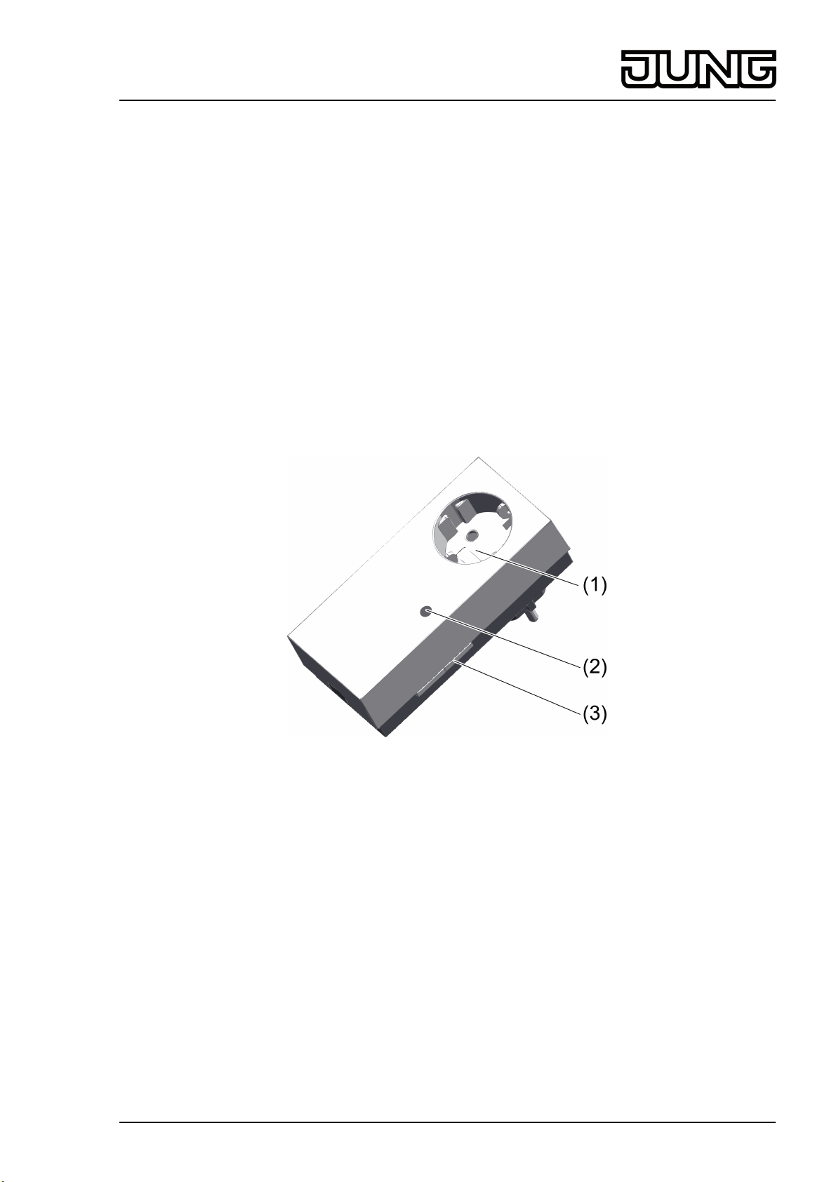
2 Device components
Figure 1: Gateway
(1) SCHUKO socket with increased contact protection
(2) Red status LED, covered
(3) Button Prog
3 Function
System information
This device is a part of the eNet system and the Radio Management system.
The range of a radio system depends on various external circumstances. The range can be
optimised by the choice of installation location.
This device complies with the requirements of the R&TTE Directive 1999/5/EC. Declaration of
Conformity and further information on the eNet and Radio Management system can be found on
our website.
The device may be operated in all EU and EFTA countries.
Intended use
- Control of eNet actuators by Radio Management transmitters
82582113
J:0082582113
1/8
13.03.2014
Page 2
eNet
Radio converter in SCHUKO housing
- Control of Radio Management actuators by eNet transmitters
- Mounting of SCHUKO sockets indoors
i The following Radio Management devices are not supported: motion detectors, presence
detectors, HVAC devices, repeaters, window contacts, KNX gateways and Centrals.
Product characteristics
- Reception of Radio Management commands and conversion into eNet commands
- Reception of eNet commands and conversion into Radio Management commands
- 24 transmitter channels from both systems can be connected
- Scene 1 to scene 5 from both systems can be recalled and changed
- All On and All Off can be recalled from both systems
- Master dimming function
Supplementary functions with eNet server:
- Update of the device software
- Repeater function
- Reading of error memory
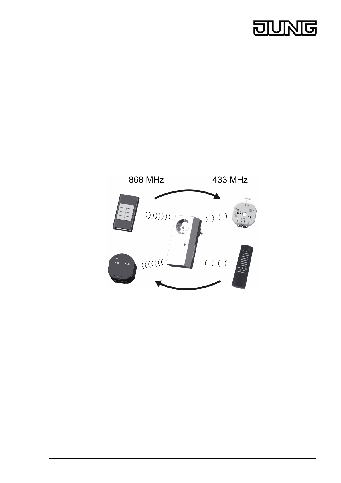
Functional description
Figure 2: Inter-system radio operation
This device serves an interface between the Radio Management, 433 MHz, and eNet, 868 MHz
systems. It allows operation of the actuators in the other system (figure 2).
i Status feedback is only provided between the transmitter and the gateway on the eNet
side.
Limited functionality
The eNet system has a wider range of functions than the radio management system. For this
reason, the following functions are not possible using the radio gateway:
- Scenes 6...16
- Threshold value functions and disabling functions
- Save switch-on brightness using transmitter
- Transmission status and status feedbacks
4 Information for electrically skilled persons
Fitting
Maintain a distance of at least 0.5 m from metal surfaces and electrical devices, e.g. microwave
ovens, hi-fi and TV systems, electronic ballasts or transformers.
Maintain a distance of at least 0.3 m between transmitter and receiver in order to prevent
overmodulation of the receiver.
82582113
J:0082582113
2/8
13.03.2014
Page 3

eNet
Radio converter in SCHUKO housing
o Insert device into a SCHUKO socket.
4.1 Commissioning
DANGER!
Electrical shock when live parts are touched.
Electrical shocks can be fatal.
During commissioning, cover the parts carrying voltage on radio transmitters
and actuators and in their surrounding area.
4.2 eNet transmitter controls Radio Management actuators
i Commissioning is not possible via the eNet server.
Connecting the eNet transmitter with the Radio Management actuator
Figure 3: Connecting the eNet transmitter
Connection takes place in two steps (figure 3). First an eNet transmitter is connected to the
gateway (A), and, in the second step, the eNet transmitter connected to one or more Radio
Management actuators (B).
First step (A):
o Press the Prog button (3) of the gateway for approx. 4 seconds.
The status LED (2) of the gateway flashes slowly. The device is in programming mode for
approx. 1 minute.
o Switch the eNet transmitter to programming mode as well (see eNet transmitter
instructions).
o Briefly press the channel or scene button of the transmitter.
The LED of the gateway lights up for approx. 5 seconds.
The gateway and transmitter exit the programming mode automatically.
Second step (B):
o Switch one or more Radio Management actuators to programming mode (see Radio
Management actuator instructions).
o Press the channel button of the eNet transmitter for longer than one second or the scene
button for longer than three seconds.
The LEDs of the Radio Management actuators light up.
The eNet transmitter is connected to the Radio Management actuators.
82582113
J:0082582113
3/8
13.03.2014
Page 4

eNet
Radio converter in SCHUKO housing
o Exit the programming mode of the Radio Management actuators (see Radio Management
actuator instructions).
Disconnect the connection to the Radio Management actuator (C)
Figure 4: Disconnecting
Disconnection should take place before an actuator is replaced, so that occupied gateway
channels can be made free again, or before a reset.
o Switch the Radio Management actuator to be disconnected to programming mode (see
actuator instructions).
The LED of the actuator flashes slowly.
o Press the transmitter channel button connected to the actuator for longer than one second
or the scene button for longer than three seconds.
The connection to the actuator is disconnected. The LED of the actuator flashes quickly.
o Exit the programming mode of the Radio Management actuators (see Radio Management
actuator instructions).
Disconnect the connection between the eNet transmitter and the gateway (D)
o Press the Prog button (3) of the gateway for approx. 4 seconds.
The LED (2) of the gateway flashes slowly. The device is in programming mode for
approx. 1 minute.
o Switch the eNet transmitter to programming mode as well (see eNet transmitter
instructions).
o Briefly press the connected button of the eNet transmitter.
The connection is disconnected. The LED flashes for a few seconds.
82582113
J:0082582113
4/8
13.03.2014
Page 5

eNet
Radio converter in SCHUKO housing
4.3 Radio Management transmitter controls eNet actuators
Connect the Radio Management transmitter and eNet actuators
Figure 5: Connecting the Radio Management transmitter
o Press the Prog button (3) of the gateway for approx. 4 seconds.
The LED (2) of the gateway flashes slowly. The device is in programming mode for
approx. 1 minute.
o Switch all the eNet actuators, which are to react to the channel or scene button, to
programming mode as well (see actuator instructions).
i Up to 10 eNet actuators can be connected at the same time.
o Press the channel button on the Radio Management transmitter for longer than one second
or the scene button for longer than three seconds.
The LED of the gateway switches to continuous on for a few seconds.
The radio transmitter is connected. The gateway and actuators exit the programming mode
automatically.
82582113
J:0082582113
5/8
13.03.2014
Page 6

eNet
Radio converter in SCHUKO housing
Disconnect the connection between the Radio Management transmitter and the eNet
actuator
Figure 6: Disconnecting
o Press the Prog button (3) of the gateway for approx. 4 seconds.
The LED (2) of the gateway flashes slowly. The device is in programming mode for
approx. 1 minute.
o Also switch all the eNet Bus actuators to be disconnected to programming mode (see
actuator instructions).
o Press the channel button on the Radio Management transmitter for longer than one second
or the scene button for longer than three seconds.
The gateway detects that the actuator was previously connected and instigates the
disconnection operation.
The eNet actuator is disconnected. The actuator exits programming mode automatically.
Resetting the device to the factory setting
All the connections in the gateway between transmitters and actuators are disconnected.
Recommissioning must take place.
i Before resetting to the factory setting, disconnect connected Radio Management actuators
(see Disconnecting the connection to the Radio Management actuator). This ensures that
setting up new connections does not cause unintentional switching operations.
o Press the Prog button for at least 20 seconds.
The status LED flashes after 4 seconds. After 20 seconds the status LED flashes faster.
o Release the Prog button and press it once again within 10 seconds.
All the connections are disconnected. The status LED flashes more slowly for approx. 5
seconds.
5 Appendix
The icon confirms the conformity of the product to the relevant guidelines.
5.1 Technical data
Rated voltage AC 230 V ~
Mains frequency 50 / 60 Hz
Rated load current 16 A (IL)
Power consumption max. 1 W
Degree of protection IP 20
82582113
J:0082582113
6/8
13.03.2014
Page 7

eNet
Radio converter in SCHUKO housing
Ambient temperature -5 ... +45 °C
Dimensions W×H×D 57×127×78 mm
eNet radio data
Radio frequency 868.3 MHz
Transmitting power max. 20 mW
Transmitting range in free field typical 100 m
Radio Management radio data
Carrier frequency 433.42 MHz (ASK)
Transmitting power max. 10 mW
Transmitting range in free field typical 100 m
5.2 Parameter list
Settings window
Device settings
Parameters Setting options, Basic
setting
Repeater mode On, Off
Basic setting: Off
Settings, channel
Parameters Setting options, Basic
setting
Local Operation On, Off
Basic setting: On
Manual commissioning On, Off
Basic setting: On
Sum status / transmission
repetitions
On, Off/Transmit 2x…11x,
Off/Transmit 4x (without
connection)
Basic setting: Off
5.3 Troubleshooting
Explanations
In addition to its other
functions, the device can be
used as a repeater. In the
"On" setting, the device
repeats all the received
telegrams.
Explanations
With this device, the
parameter has no function.
With this device, the
parameter has no function.
With this device, the
parameter has no function.
Additional connections between the transmitter and receiver cannot be saved.
Cause: all the memory locations in the gateway are occupied.
Disconnect connections no longer required.
Or
Reset the gateway to the default setting and reconnect the transmitter and actuators.
Or
Use an additional gateway for new connections.
5.4 Warranty
We reserve the right to make technical and formal changes to the product in the interest of
technical progress.
We provide a warranty as provided for by law.
Please send the unit postage-free with a description of the defect to our central customer
service office.
82582113
J:0082582113
7/8
13.03.2014
Page 8

eNet
Radio converter in SCHUKO housing
ALBRECHT JUNG GMBH & CO. KG
Volmestraße 1
58579 Schalksmühle
Telefon: +49.23 55.8 06-0
Telefax: +49.23 55.8 06-2 04
kundencenter@jung.de
www.jung.de
Service Center
Kupferstr. 17-19
44532 Lünen
Germany
82582113
J:0082582113
8/8
13.03.2014
 Loading...