

Page 1
eNet
Radio switch actuator for rail mounting, 1-channel
Radio switch actuator for rail mounting, 1-channel
Art. No. : FM AS 16 REG
Operating instructions
1 Safety instructions
Electrical equipment may only be installed and fitted by electrically skilled persons.
Serious injuries, fire or property damage possible. Please read and follow manual fully.
Danger of electric shock. Always disconnect before carrying out work on the devise or
load. At the same time, take into account all circuit breakers that supply dangerous
voltage to the device or load.
Danger of electric shock. During installation and cable routing, comply with the
regulations and standards which apply for SELV circuits.
Danger of electric shock. Device is not suitable for disconnection from supply voltage.
Fire hazard! Operation exclusively with the power supplies listed under accessories
These instructions are an integral part of the product, and must remain with the end
customer.
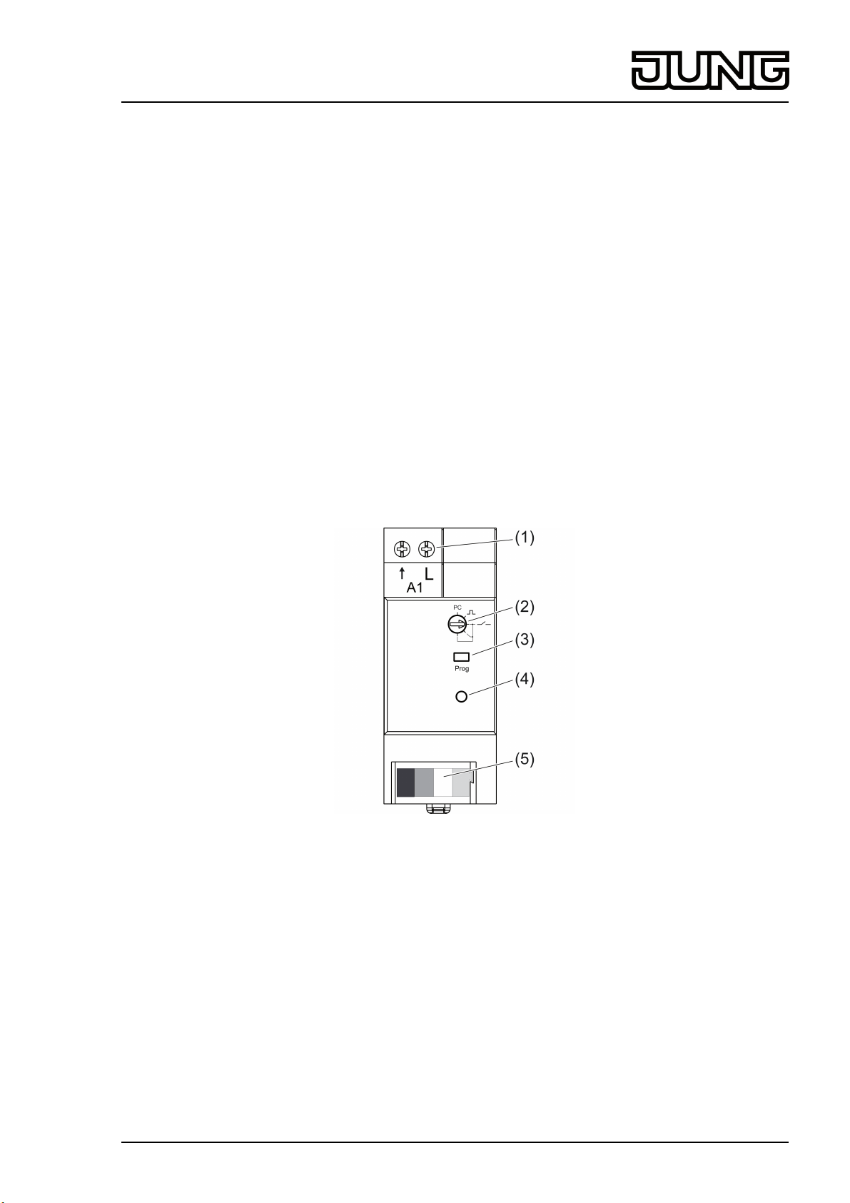
2 Device components
(1) Load connection
(2) Operating mode switch
(3) Button Prog
(4) Status LED
(5) Bus line connection
Figure 1: Device components
3 Function
System information
This device is a part of the eNet system.
High transmission reliability at a radio frequency of 868 MHz is achieved by the transmission
behaviour and bidirectional data transfer.
The range of a radio system depends on various external circumstances. The range can be
optimised by the choice of installation location.
82581713
J:0082581713
1/11
11.03.2014
Page 2

eNet
Radio switch actuator for rail mounting, 1-channel
You can find further information about the eNet system on our website.
The device may be operated in all EU and EFTA countries.
Intended use
- Switching of lighting
- Operation with suitable eNet radio transmitters
- Operation with power supply RMD and receiver module RMD cover or eNet server (see
accessories)
- Installation in distribution boxes on DIN rail according to EN 60715
Product characteristics
- Operating mode switch for switch/push-button actuator switch-over or parameterisation via
eNet server
- Status feedback to radio transmitter
- Scene operation possible
- Switchable output with Prog button
- Status indicator via LED
Switching mode of operation:
- Switch-on telegram: Device switches on
- Switch-off telegram: Device switches off
Operating mode buttons:
- Relay contact remains closed as long as ON or OFF telegrams are being received
- The maximum switch-on time is 60 seconds
Can be set with eNet server:
- Flash function
- Run-on time
- Switch-on delay / switch-off delay
- Operation as NO or NC contacts
- Switch-off warning
- Minimum switching repeat time
- Operation locks
- Continuous on, Continuous off
i If settings are changed with the eNet server, operation and signalling could vary from what
is described here.
i The parameter list is in the Internet in the documentation for this device.
Supplementary functions with eNet server:
- Update of the device software
- Reading of error memory
Behaviour in case of bus voltage failure and return
If the bus voltage fails, the actuator switches off. The response to bus voltage return can be
parameterised with eNet server. Default setting: Off.
4 Operation
Operation is with radio transmitters, please observe the radio transmitter instructions.
Operation with Prog button
o Press Prog button briefly.
The load switches on or off.
Status-LED lights up: output is switched on.
Status-LED off: output is switched off.
82581713
J:0082581713
2/11
11.03.2014
Page 3
eNet
Radio switch actuator for rail mounting, 1-channel
5 Information for electrically skilled persons
5.1 Fitting and electrical connection
DANGER!
Electrical shock when live parts are touched.
Electrical shocks can be fatal.
Before working on the device, disconnect the power supply and cover up live
parts in the working environment.
Fitting the device
o Mount device on DIN rail. Output terminals must be at the top.
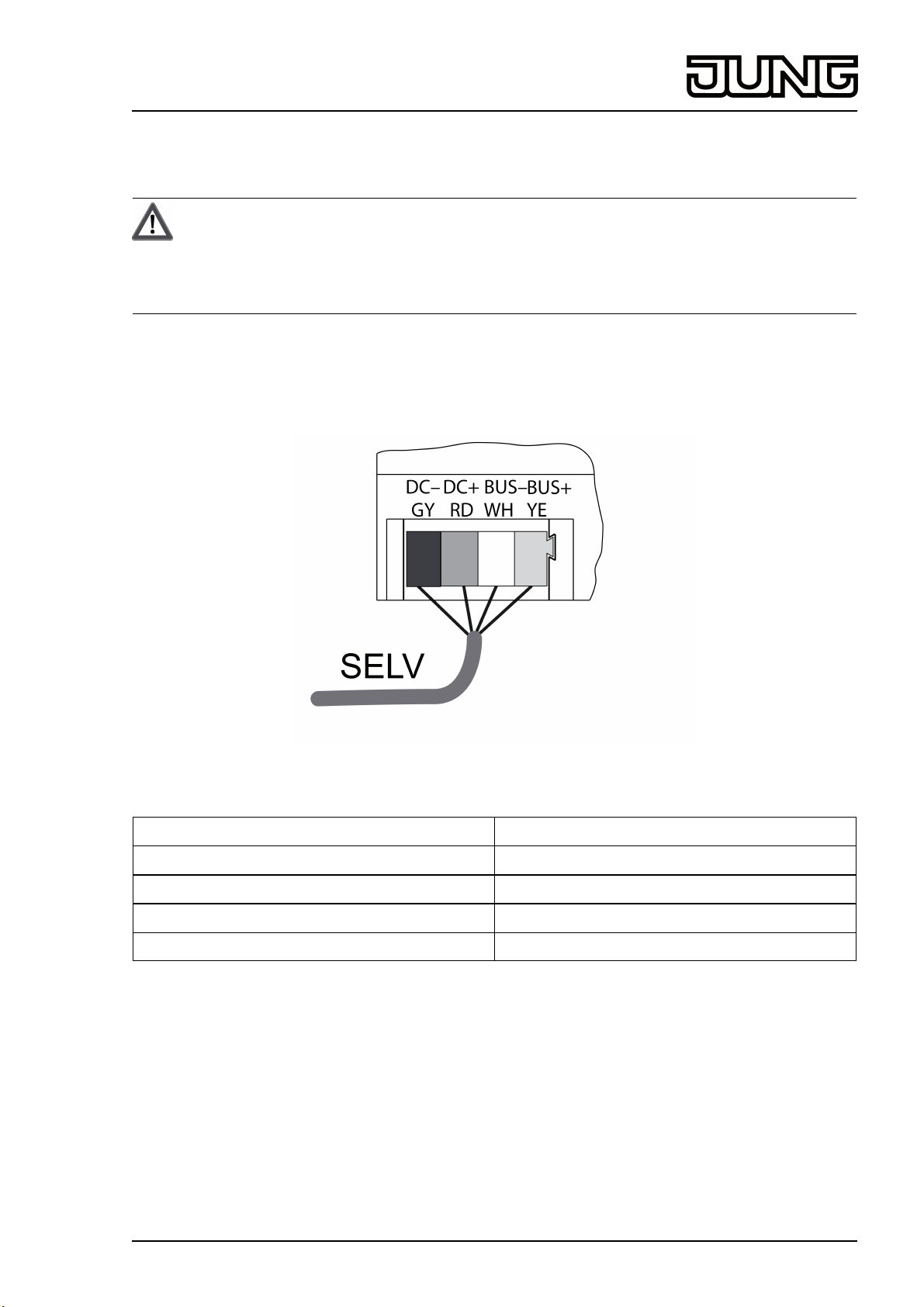
Connect bus line
Figure 2: Connection diagram of bus line
Labelling / Colour Connection
DC– / GY dark grey Power supply –
DC+ / RD red Power supply +
Bus– / WH white Data cable –
Bus+ / YE yellow Data cable +
As bus line, use e.g. J-Y(St)Y 2x2x0.8
o Connect the device with bus line (figure 2) to the RMD reception module and power supply
(see instructions of RMD reception module and power supply).
82581713
J:0082581713
3/11
11.03.2014
Page 4
eNet
Radio switch actuator for rail mounting, 1-channel
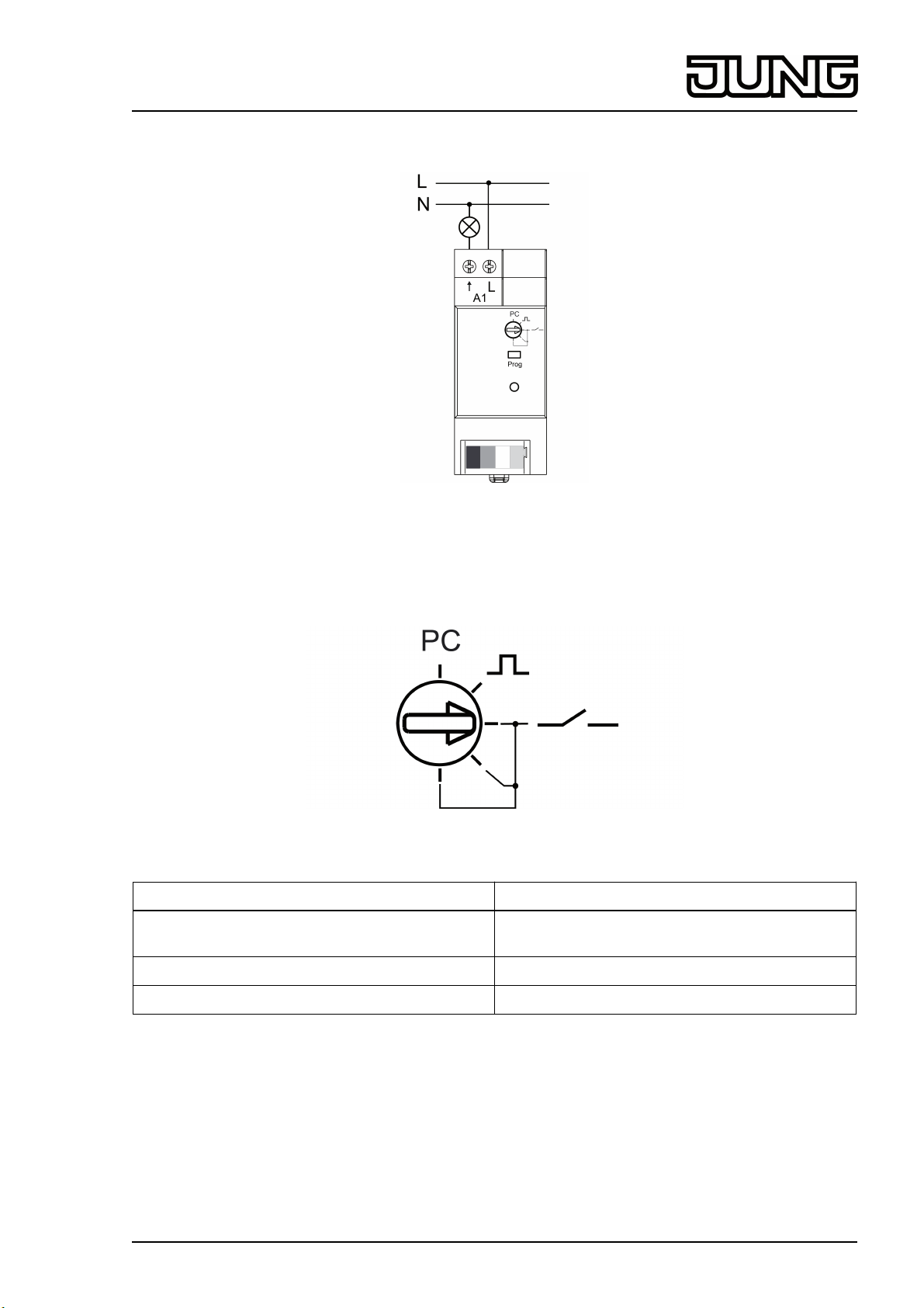
Connecting loads
Figure 3: Connection example
o Connect device as shown in the connection example (figure 3).
Presetting the operating mode
Figure 4: Operating mode switch
Switch position Function
PC Operating mode and parameter set with eNet
server.*)
M Operating mode buttons
K Switching mode of operation
*) If the operating mode switch is turned from the position PC to another operating mode, the
parameters are set to the default setting. The settings made with the eNet server will be
lost.
Mains voltage is switched off.
o Set the operating mode switch.
82581713
J:0082581713
4/11
11.03.2014
Page 5

eNet
Radio switch actuator for rail mounting, 1-channel
5.2 Commissioning
DANGER!
Electrical shock when live parts are touched.
Electrical shocks can be fatal.
During commissioning, cover the parts carrying voltage on radio transmitters
and actuators and in their surrounding area.
i The actuator can also be commissioned with eNet server as an alternative to the
commissioning described here.
Connecting actuator to radio transmitters
Load is switched off.
o Press the Prog button for longer than 4 seconds.
The load switches on.
The status LED flashes after 4 seconds and the load switches off. The actuator is in
programming mode for approx. 1 minute.
o Switch radio transmitter to programming mode (see radio transmitter instructions).
o Trigger telegram on the radio transmitter.
The status LED of the actuator lights up for 5 seconds.
The actuator is connected to the radio transmitter. The actuator and radio transmitter exit
the programming mode automatically.
i If the status LED of the actuator flashes 3 times at 1-second intervals for approx.
5 seconds, then the programming operation was not successful. All the memory locations
in the actuator or radio transmitter are occupied.
i All On and All Off buttons of a radio transmitter are connected to the actuator automatically
as soon as the first connection to the radio transmitter takes place.
i Scene buttons must be connected separately.
Disconnecting connection to a radio transmitter
o Carry out the same steps as when connecting (see Connecting actuator to radio
transmitters).
The status LED flashes quickly for 5 seconds. The actuator is disconnected from the radio
transmitter. The actuator and radio transmitter exit the programming mode automatically.
i If there several connections or scene buttons for a radio transmitter, all connections must
be disconnected individually.
i All On and All Off buttons of a radio transmitter are disconnected automatically as soon as
the last connection of the corresponding output to the radio transmitter is disconnected.
Manual disconnection is not possible.
Resetting the device to the factory setting
All connections to radio transmitters are disconnected and parameters are reset to default
setting. If the operating mode switch is on PC, the operating mode switching is set.
i The connections in the radio transmitters are preserved and must be deleted separately.
Load is switched off.
o Press the Prog button for at least 20 seconds.
The load switches on.
The status LED flashes after 4 seconds and the load switches off. The status LED flashes
faster after 20 seconds.
o Release Prog button and press briefly once again within 10 seconds.
The status LED flashes more slowly for approx. 5 seconds.
The device is reset to default setting.
82581713
J:0082581713
5/11
11.03.2014
Page 6

eNet
Radio switch actuator for rail mounting, 1-channel
6 Appendix
6.1 Technical data
Rated voltage AC 230 V ~
Mains frequency 50 / 60 Hz
Ambient temperature -5 ... +45 °C
Switching current for AC 230 V ~
Ohmic 16 A
For switching current >10A connecting cable 2.5mm²
Fluorescent lamps 4 AX
Minimum switching current AC 100 mA
Contact type µ
Standby power max. 0.2 W
Connected load
Incandescent lamps 2300 W
HV halogen lamps 2000 W
Tronic transformers 1500 W
HV-LED lamps typical 500 W
Compact fl lamp. typical 500 W
Inductive transformers 1000 VA
Fluorescent lamps, uncompensated 920 VA
Capacitive load 690 VA (560 µF)
Connection of load terminals
single stranded 1.5 ... 4 mm²
finely stranded without conductor sleeve 0.75 ... 4 mm²
Finely stranded with conductor sleeve 0.5 ... 2.5 mm²
Fitting width 36 mm / 2 modules
Bus line
Rated voltage DC 12 V SELV
Current consumption max. 20 mA
Connection, Bus Connection terminal
Cable length max. 3 m
6.2 Parameter list
Settings window
Device settings
Parameters Setting options, Basic
setting
Manual commissioning On, Off
Basic setting: On
Settings, channel
Parameters Setting options, Basic
setting
Manual commissioning On, Off
Basic setting: On
Explanations
Blocks manual commissioning
for all device channels. In the
"Off" setting, the device
cannot be reset to the factory
setting.
Explanations
Blocks manual commissioning
for the device channel. In the
"Off" setting, the device
cannot be reset to the factory
setting.
82581713
J:0082581713
6/11
11.03.2014
Page 7

eNet
Radio switch actuator for rail mounting, 1-channel
Operating mode Switching
Buttons
Flashing
Continuous on
Continuous off
Basic setting: Switching
Switching
After switch-on, the device
remains stable in the "On"
state, and stable in the "Off"
state after switch-off.
Buttons
The device switches "On"
when any channel button of a
radio transmitter is pressed
and "Off" when the button is
released. It is irrelevant
whether the "On" or "Off"
channel button is pressed.
Flashing
Switch-on starts flashing and
switch-off stops flashing. The
default flash frequency is 1
Hz. This frequency is also the
maximum flash frequency.
The flash frequency can be
changed using parameters.
The parameter "Switch-off
delay" is used for the pulse
time and the parameter
"Switch-on delay" for the
pause time.
Local Operation On, Off
Basic setting: On
Manual switch-off of the runon time
On, Off
Basic setting: Off
Continuous on
The output switches to
continuously "On". All
operations of radio
transmitters and the Prog
button are ignored.
Continuous off
The output switches to
continuously "Off". All
operations of radio
transmitters and the Prog
button are ignored.
Blocks the output for operation
using the Prog button.
Allows manual switch-off of a
running run-on time. If the
parameter is switched off, then
a switch-off command will also
switch the actuator on. This
parameter is directly
connected to the "Run-on
time" parameter.
82581713
J:0082581713
7/11
11.03.2014
Page 8

eNet
Radio switch actuator for rail mounting, 1-channel
Switch-on delay 0 s … 24 h
Basic setting: 0 s
Switch-off delay 0 s … 24 h
Basic setting: 0 s
The load switches on after a
delay. Repeated switch-on
commands restart the delay
time. If the load has not yet
been switched on due to the
delay when a switch-off
command comes, then the
load will remain off.
In Flashing operating mode,
the pause times are set using
this parameter.
Note: The set time apply to
operation using radio
transmitters. The relay is
switched immediately when
the Prog button is pressed.
The load switches off after a
delay. Repeated switch-off
commands restart the delay
time. If the load has not yet
been switched off due to the
delay when a switch-on
command comes, then the
load will remain on.
In Flashing operating mode,
the pulse times are set using
this parameter.
Note: The set time apply to
operation using radio
transmitters. The relay is
switched immediately when
the Prog button is pressed.
Run-on time 0 s … 24 h
Basic setting: 0 s
Behaviour after the end of the
disabling function
On
Off
no change
Last value
Basic setting: No change
Behaviour on voltage return On
Off
Last value
Configured brightness
Basic setting: Off
As soon as a run-on time has
been entered, the actuator will
no longer remain on
permanently, but only for the
length of the run-on time. The
run-on time is restarted if
actuation is repeated. This
parameter is directly
connected to the "Manual
switch-off of run-on time"
parameter.
Note: The set time apply to
operation using radio
transmitters. The relay is
switched immediately when
the Prog button is pressed.
Behaviour of the output when
a block is removed.
Defines the behaviour of the
output after voltage return.
RMD design: Bus voltage
return
82581713
J:0082581713
8/11
11.03.2014
Page 9

eNet
Radio switch actuator for rail mounting, 1-channel
Timer behaviour, voltage
return
Off
Restart
Basic setting: Off
Switch-off warning On, Off
Basic setting: Off
Priority, lock-out protection 0...4
Basic setting: 1
Priority, restraint 0...4
Basic setting: 2
Specifies whether the timers
for switch-on delay, switch-off
delay and run-on time remain
off after voltage return or
whether they restart. Directly
connected to the parameters
"Switch-on delay", "Switch-off
delay" and "Run-on time".
If the switch-off warning is
active, the light is not switched
off directly. The light goes off
30, 15 and 6 seconds before
permanent switch-off. During
the switch-off warning, a
switch-on telegram effects
direct switch-on. It is not
possible to terminate the time
using a switch-off telegram.
Specifies the priority for
recalling and removing a
scene of type Lock-out
protection for the channel.
Specifies the priority for
recalling and removing a
scene of type Forced position
for the channel.
Priority, wind alarm 0...4
Basic setting: 3
Priority, sun protection 0...4
Basic setting: 0
Priority, twilight 0...4
Basic setting: 0
Switch-off on brightness
overshoot
On, Off
Basic setting: On
Specifies the priority for
recalling and removing a
scene of type Wind alarm for
the channel.
Specifies the priority for
recalling and removing a
scene of type Sun protection
for the channel.
Specifies the priority for
recalling and removing a
scene of type Twilight for the
channel.
Allows automatic switch-off
according to the brightness. If
the parameter is On, then the
light controller switches off
automatically when the
brightness setpoint is greatly
exceeded. This parameter is
not yet active, as a light
controller has not yet been
implemented.
82581713
J:0082581713
9/11
11.03.2014
Page 10

eNet
Radio switch actuator for rail mounting, 1-channel
Switch-on on brightness
undershoot
On, Off
Basic setting: Off
Invert switching output On, Off
Basic setting: Off
Minimum switching repeat
time
100 ms ... 10 sec
Basic setting: 100 ms
Allows automatic switch-on
according to the brightness. If
the parameter is On, then the
light controller switches on
automatically when the
brightness setpoint is greatly
undershot. We recommend
only using the parameter in
connection with the parameter
"Switch-off on brightness
overshoot". This parameter is
not yet active, as a light
controller has not yet been
implemented.
Inverts the switching output
from NO contact function
(factory setting) to NC contact
function
Limits the switching speed of
the device by increasing the
value, in order to protect the
load, for example. Only when
the set time has elapsed is
switching possible again. The
last command during the
blocking time is executed after
a delay. The switching repeat
time starts after each
switching operation.
Operating hours 0...65535
Basic setting: Current value
The time is counted during
which the load is physically
switched on (relay contact
closed).
This parameter can be reset to
"0", for example after
exchanging the load.
The Reset button is used to
reset the counter to "0". The
device must be programmed
to apply the change.
Information window
During channel selection in the Information window, the following settings can be made or
values displayed.
Display value Explanations
Load state The load can be switched on or off.
Restraint Display of forced position status.
Switching cycle counter Display of the switching cycles with the factor
10, e.g. the value 5 x 10 is displayed for 50
switching cycles.
Total operating hours Display of the operating hours since the start
of operation.
Operating hours Display of the operating hours since the last
restart in the Settings window.
i The value can be updated using the arrow next to the display values.
82581713
J:0082581713
10/11
11.03.2014
Page 11

eNet
Radio switch actuator for rail mounting, 1-channel
6.3 Accessories
Power supply 12 V, for rail mounting Art. No. NT 1220 REG VDC
Master receiver for rail mounting Art. No. FM FK 32 REG
eNet server Art. No. ENET-SERVER
6.4 Warranty
We reserve the right to make technical and formal changes to the product in the interest of
technical progress.
We provide a warranty as provided for by law.
Please send the unit postage-free with a description of the defect to our central customer
service office.
ALBRECHT JUNG GMBH & CO. KG
Volmestraße 1
58579 Schalksmühle
Telefon: +49.23 55.8 06-0
Telefax: +49.23 55.8 06-2 04
kundencenter@jung.de
www.jung.de
Service Center
Kupferstr. 17-19
44532 Lünen
Germany
82581713
J:0082581713
11/11
11.03.2014
 Loading...