

Page 1
KNX RF radio transmitter module
KNX RF radio transmitter module 1-gang
Art. no.: ..5071 RF TSM
KNX RF radio transmitter module 2-gang
Art. no.: ..5072 RF TSM
KNX RF radio transmitter module 3-gang
Art. no.: ..5073 RF TSM
KNX RF radio transmitter module 4-gang
Art. no.: ..5074 RF TSM
Operating instructions
1 Safety instructions
Electrical devices may only be mounted and connected by electrically skilled persons.
Serious injuries, fire or property damage possible. Please read and follow manual fully.
The radio communication takes place via a non-exclusively available transmission path, and is
therefore not suitable for safety-related applications, such as emergency stop and emergency
call.
These instructions are an integral part of the product, and must remain with the end customer.
2 Battery safety instructions
This device or its accessories are supplied with batteries in the form of button cells.
DANGER! Batteries can be swallowed. This can lead directly to death by suffocation. Danger-
ous substances may cause severe internal burns leading to death within 2 hours.
Keep new and used batteries away from children.
Do not use devices if the battery compartment does not close securely and keep away from
children.
If you suspect that a battery has been swallowed or is in any orifice of the body, seek immediate
medical attention.
WARNING! Improper handling of batteries can result in explosion, fire or chemical burn due to
leakage.
Do not heat or throw batteries into fire.
Do not reverse polarity, short-circuit or recharge batteries.
Do not deform or disassemble batteries.
Replace batteries only with an identical or equivalent type.
Remove empty batteries immediately and dispose of in an environmentally friendly manner.
32595413 29.07.2019
j0082595413
1 / 6
Page 2
KNX RF radio transmitter module
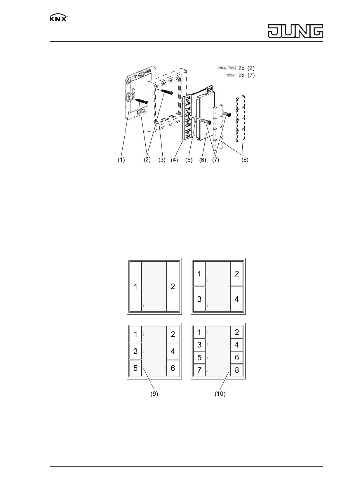
3 Device components
Figure1: 4-gang radio wall transmitter module
(1) Base plate
(2) Fastening screws for the base plate
(3) Design frame
(4) Wall transmitter module
(5) Battery compartment
(6) Cover
(7) Fastening screws
(8) Cover kit
Figure2: Button assignment of wall transmitter module 1-gang, 2-gang, 3-gang and 4-gang
(9) Status LED per button pair, green
(10) Acknowledgement/transmission LED, red
32595413 29.07.2019
j0082595413
2 / 6
Page 3

KNX RF radio transmitter module
4 Function
System information
This device is a product of the KNX system and complies with the KNX directives. Detailed technical knowledge obtained in KNX training courses is a prerequisite to proper understanding.
The range of a radio system depends on various external circumstances. The range can be optimised by the choice of installation location. The product documentation for this device contains
application basics for the KNX radio system.
Planning, installation and commissioning are carried out with the aid of KNX-certified software
of version ETS5 or higher. You can find the up-to-date product database, technical descriptions
and Declaration of Conformity on our Internet site.
Intended use
– Radio operation of loads, e.g. light on/off, dimming, Venetian blinds up/down, brightness
values, calling up and saving light scenes.
– Operation in cabled KNX systems via media coupler (see chapter Accessories)
Product characteristics
– Push-button sensor functions switching, dimming, Venetian blind control, value transmit-
ter, scene recall
– One, two, three or four button pairs for push-button sensor function or rocker function
– Status indicator via status LED
– Integrated temperature sensor
– Battery-powered device
Energy saving mode
The device switches to the energy saving mode after a preset time. In energy saving mode, the
LEDs remains switched off. During operation, the energy saving mode is exited.
Operations during energy saving mode are executed immediately.
Cyclical transmission of temperature values reduces the lifespan of the battery.
5 Operation
Operating a function or load
■ Switch: Short press on button.
■ Dim: Long press on the button.
■ Move Venetian blind: Long press on button.
■ Stop or adjust Venetian blind: Short press on button.
■ Call up light scene: Short press on button.
■ Save light scene: Press button for longer than 5 seconds.
■ Set value: Press button briefly.
LED function
Acknowledgement/transmission LED (10) lights up after pressing a button and goes out as soon
as the feedback has been received from the actuator. After the acknowledgement/transmission
LED (10) goes out, the status LED (9) displays the actuator feedback. The display duration can
be changed by the programming or can be dispensed with entirely.
The acknowledgement/transmission LED (10) flashes rapidly if a transmission error occurs.
32595413 29.07.2019
j0082595413
3 / 6
Page 4

KNX RF radio transmitter module
6 Information for electrically skilled persons
6.1 Fitting and electrical connection
Fitting the device
To ensure good transmission quality, keep a sufficient distance from any possible sources of in-
terference, e.g. metallic surfaces, microwave ovens, hi-fi and TV systems, ballasts or transformers.
■ Insert battery (see chapter Commissioning).
■ Screw or glue the base plate (1) to an even surface. The
the top.
■ Position the design frame (3) on the base plate.
■ Screw wall transmitter module (4) to base plate.
Screwing the screws (7) too tightly could impair functions of the wall transmitter.
■ Snap on the buttons (8) (see Accessories).
Information on gluing mounting
To be able to fasten the wall transmitter safely, the substrate must be flat and free of dust and
grease.
■ Remove the rear, unpunched film of the enclosed adhesive pad.
■ Align the adhesive pad, stick it to the surface and smooth it out. Remove air bubbles.
■ Remove the two inner segments of the front film.
■ Align the base plate to the external punching and stick it on.
In the case of multiple combinations, the abutting sides of the adhesive pads must be cut
along the external punching using a ruler and a cutter (Figure 3).
TOP/OBEN
label has to be at
Figure3: Cutting the adhesive pads for multiple combinations
If necessary, after mounting the wall transmitter in the CD program, carefully remove the
excess adhesive film in the corners.
6.2 Commissioning
Inserting the battery
Obey the battery safety instructions.
The battery holder is located on the rear side.
■ Carefully remove cover (6) from wall transmitter .
Keep contacts of batteries and device free of grease.
■ Apply the battery to the positive contact of the battery compartment (5). Observe polarity:
the positive pole of the battery must be at the top.
■ Press gently on battery to snap it in.
■ Snap on the cover (6).
Loading the physical address and application software
Project design and commissioning with ETS5 or more recent.
32595413 29.07.2019
j0082595413
4 / 6
Page 5

KNX RF radio transmitter module
The device is ready for operation.
If the device does not contain any application software, or contains the wrong application
software, then the acknowledgement/transmission LED (10) flashes slowly for
approx. 3 seconds.
Figure4: Activating programming mode
■ Activate programming mode: Press and hold push-button at the upper left (11). Then
press push-button at the lower right (12).
The acknowledgement/transmission LED (10) flashes rapidly.
■ Load the physical address and domain address into the device.
The acknowledgement/transmission LED (10) returns to its previous state – off, on, or
flashing slowly.
■ Write the physical address and domain address on the device label.
■ Load the application software into the device.
Before updating the system software or before a later correction of the programming, re-
place a battery with a new, unused battery.
7 Disposal of batteries
Remove empty batteries immediately and dispose of in an environmentally friendly
manner. Do not throw batteries into household waste. Consult your local authorities
about environmentally friendly disposal. According to statutory provisions, the end
consumer is obligated to return used batteries.
8 Technical data
KNX medium RF1.R
Commissioning mode S-mode
Rated voltage DC 3 V
Battery type 1×Lithium CR 2450N
Ambient temperature -5 ... +45 °C
Degree of protection IP20
Protectionclass III
Radio frequency 868.0 ... 868.6 MHz
Transmission capacity max. 20 mW
Transmitting range in free field typ. 100 m
Receiver category 2
32595413 29.07.2019
j0082595413
5 / 6
Page 6

KNX RF radio transmitter module
9 Troubleshooting
After a button-press, the actuation/transmission LED (10) flashes slowly for 3 seconds.
Cause: battery in the wall transmitter is almost empty.
Changing the battery (see chapter Commissioning – Inserting the battery).
Receiver does not respond, actuation/transmission LED (10) flashes slowly for 3 seconds.
Cause: The wall transmitter cannot transmit the telegram, e.g. due to a missing group address.
Correct the programming.
Receiver does not react, actuator feedback is not displayed.
Cause 1: Radio range exceeded. Structural obstacles reduce the range.
Use of the media coupler as a radio repeater.
Cause 2: Receiver or media coupler is not ready for operation.
Check the receiver, mains voltage or media coupler.
Cause 3: There are radio faults, e.g. through outside radio.
Eliminate radio interference.
10 Accessories
Cover kit 1-gang Art. no. ..501 TSA..
Cover kit 2-gang Art. no. ..502 TSA..
Cover kit 3-gang Art. no. ..503 TSA..
Cover kit 4-gang Art. no. ..504 TSA..
KNX RF radio converter Art. no. MK100RF
11 Conformity
Hereby Albrecht Jung GmbH & Co. KG declares that the radio system type
Art. no. ..5071 RF TSM/..5072 RF TSM/..5073 RF TSM/..5074 RF TSM
corresponds to the directive 2014/53/EU. You can find the full article number on the device. The
complete text of the EU Declaration of Conformity is available under the Internet address:
www.jung.de/ce
12 Warranty
The warranty is provided in accordance with statutory requirements via the specialist trade.
ALBRECHT JUNG GMBH & CO. KG
Volmestraße 1
58579 Schalksmühle
GERMANY
Telefon: +49 2355 806-0
Telefax: +49 2355 806-204
kundencenter@jung.de
www.jung.de
32595413 29.07.2019
j0082595413
6 / 6
 Loading...