

Page 1
Product documentation
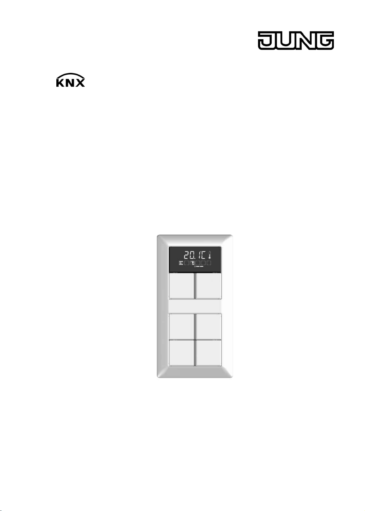
KNX Room controller display compact module
Art.-No.: 4093 KRM TS D
ALBRECHT JUNG GMBH & CO. KG
Volmestraße 1
D-58579 Schalksmühle
Telefon: +49.23 55.8 06-0
Telefax: +49.23 55.8 06-1 89
E-mail: mail.info@jung.de
Internet: www.jung.de
www.jung-katalog.de
Issue: 20.10.2009
13557800
Page 2

Product documentation
Content
1 Product definition 4 ................................................................................................................
1.1 Product catalogue 4 ...........................................................................................................
1.2 Function 4 ..........................................................................................................................
1.3 Accessories 6 ....................................................................................................................
2 Installation, electrical connection and operation 7 .............................................................
2.1 Safety instructions 7 ..........................................................................................................
2.2 Device components 8 ........................................................................................................
2.3 Fitting and electrical connection 9 .....................................................................................
2.4 Commissioning 13 .............................................................................................................
2.5 Operation 15 ......................................................................................................................
2.5.1 Basic display 16 .........................................................................................................
2.5.2 Second operating level 17 ..........................................................................................
3 Technical data 26 ....................................................................................................................
4 Software description 27 .........................................................................................................
4.1 Software specification 27 ...................................................................................................
4.2 Software "Continuous controller module 3gang 146A11" 28 .............................................
4.2.1 Scope of functions 28 .................................................................................................
4.2.2 Notes on software 31 .................................................................................................
4.2.3 Object table 32 ...........................................................................................................
4.2.3.1 Object table, pushbutton sensor function section 32 ..........................................
4.2.3.2 Object table, controller function section 45 .........................................................
4.2.3.3 Display object table 62 ........................................................................................
4.2.4 Functional description 66 ...........................................................................................
4.2.4.1 Pushbutton sensor 66 .........................................................................................
4.2.4.1.1 Operation concept and button evaluation 66 ..............................................
4.2.4.1.2 "Switching" function 73 ................................................................................
4.2.4.1.3 "Dimming" function 74 .................................................................................
4.2.4.1.4 "Venetian blind" function 76 ........................................................................
4.2.4.1.5 Value transmitter function 80 ......................................................................
4.2.4.1.6 "Scene extension" function 83 .....................................................................
4.2.4.1.7 Function "2-channel operation" 84 ..............................................................
4.2.4.1.8 "Controller extension" function 86 ...............................................................
4.2.4.1.9 "Fan control" function 87 .............................................................................
4.2.4.1.10 "Controller operating mode" function 88 ......................................................
4.2.4.1.11 "Setpoint shift" function 89 ..........................................................................
4.2.4.1.12 "Change in the display reading" function 90 ................................................
4.2.4.1.13 Status LED 91 .............................................................................................
4.2.4.1.14 Disabling function 93 ...................................................................................
4.2.4.1.15 Transmission delay 96 ................................................................................
4.2.4.1.16 Alarm message 97 ......................................................................................
4.2.4.2 Room temperature controller 98 .........................................................................
4.2.4.2.1 Operating modes and operating mode change-over 98 ..............................
4.2.4.2.2 Control algorithms and calculation of command values 101 .......................
4.2.4.2.3 Adapting the control algorithms 108 ............................................................
4.2.4.2.4 Operating mode change-over 111 ..............................................................
4.2.4.2.5 Temperature setpoints 120 .........................................................................
4.2.4.2.6 Room temperature measurement 134 ........................................................
4.2.4.2.7 Command value and status output 137 ......................................................
4.2.4.2.8 Fan controller 141 .......................................................................................
4.2.4.2.9 Disable functions of the room temperature controller 148 ...........................
4.2.4.2.10 Valve protection 149 ...................................................................................
4.2.4.3 Room temperature controller extension 150 .......................................................
4.2.4.3.1 Connection to room temperature controller 150 ..........................................
Art.-No.: 4093 KRM TS D
Page 2 of 241
Page 3

Product documentation
4.2.4.3.2 Operating functions 153 ..............................................................................
4.2.4.3.3 Display functions 155 ..................................................................................
4.2.4.3.4 Room temperature measurement 157 ........................................................
4.2.4.3.5 Behaviour after a device restart 158 ...........................................................
4.2.4.4 Light scene function 159 .....................................................................................
4.2.4.5 Display 162 .........................................................................................................
4.2.4.5.1 Displayed information 162 ...........................................................................
4.2.4.5.2 Display control 165 ......................................................................................
4.2.4.6 Delivery state 168 ...............................................................................................
4.2.5 Parameters 169 ..........................................................................................................
4.2.5.1 General parameters 169 .....................................................................................
4.2.5.2 Parameter for room temperature measurement 174 ..........................................
4.2.5.3 Parameters on the pushbutton sensor function section 176 ...............................
4.2.5.4 Parameter for the controller function section 211 ...............................................
4.2.5.5 Parameters for the display 233 ...........................................................................
4.2.5.6 Parameter on scene function 236 .......................................................................
5 Appendix 239 ...........................................................................................................................
5.1 Index 239 ...........................................................................................................................
Art.-No.: 4093 KRM TS D
Page 3 of 241
Page 4

Product definition
1 Product definition
1.1 Product catalogue
Product name: Room controller display compact module
Use: Sensor
Design: UP (concealed)
Art.-No.: 4093 KRM TS D
1.2 Function
This device combines the functions of a KNX/EIB bus coupling unit, a single-room temperature
controller with setpoint specification, and a push-button sensor, in just one bus subscriber. The
combination of these functions makes it possible, for example, to control the light, the blinds,
and the room temperature centrally from the entry area of a room. The room temperature
controller and pushbutton sensor functions are each independent function sections of the device
with their own parameter blocks in the ETS.
The device has 3 control surfaces that can be used to operate the integrated room temperature
controller and the pushbutton sensor. The functions can be configured in the ETS. Optionally,
the number of control surfaces can be expanded to include up to 4 additional ones by
connecting an expansion module to the basic unit. Configuration and commissioning of the
expansion module is clearly structured and easy to perform using the application program of the
basic unit.
Pushbutton sensor functionality:
When a rocker or button is pressed, the device transmits telegrams to the KNX/EIB, depending
on the ETS parameter settings. These can be, for instance, telegrams for switching or
pushbutton control, for dimming or for controlling blinds. It is also possible to program value
transmitter functions, such as dimming value transmitters, light scene extensions, temperature
value transmitters or brightness value transmitters.
In connection with a room temperature controller equipped with a 1-byte object for change-over
of operating modes, the device can be used as a full-featured controller extension. The device
can also be used for presence detection or for setpoint shifting purposes and to indicate
different controller states.
The operation concept of a control surface can be configured in the ETS either as a rocker
function or alternatively as a push-button function. With the rocker function, one control surface
is divided into two actuation pressure points with the same basic function. In the push-button
function either a control surface is divided into 2 functionally separate actuation pressure points
(2 buttons), or a control surface is evaluated as single-surface operation (only one button).
With the rocker function and the double-surface push-button function, the button arrangement
can be set either as "vertical" (top-bottom operation) or as "horizontal" (left-right operation) for
each control surface. With the rocker function it is also possible to trigger special functions using
full-surface operation.
The device has two status LEDs for each of the lower control surfaces and for the control
surfaces of the expansion module, which, according to the function of the rocker or button can
be internally connected to the operating function. Each status LEDs can then also signal
completely independent display information, operating states of room temperature controllers or
indicate the results of logic value comparisons, flash or be permanently switched on or off. The
control surface next to the display does not have status LEDs.
Room temperature controller functionality
The device can be used for single-room temperature control. Depending on the operating mode,
the current temperature setpoint and on the room temperature, a command value for heating or
cooling control can be sent to the KNX/EIB for the control circuit. In addition to the heating or
cooling basic level, activating an additional heater and/or cooling unit means that an additional
heating or cooling unit can be used. In this connection, you can set the temperature setpoint
difference between the basic and the additional level by a parameter in the ETS. For major
deviations between the temperature setpoint and the actual temperature, you can activate this
additional level to heat up or cool down the room faster. You can assign different control
Art.-No.: 4093 KRM TS D
Page 4 of 241
Page 5

Product definition
algorithms to the basic and additional levels.
For heating and cooling functions, you can select continuous or switching PI or switching 2-point
feedback control algorithms.
The room temperature can be recorded either by the internal or by an external temperature
sensor. Combined temperature recording by both sensors can also be configured.
The controller distinguishes between different operating modes (comfort, standby, night, frost/
heat protection) each with their own temperature setpoints for heating or cooling.
General:
A bus coupling unit is already permanently integrated in the device, allowing the device to be
connected directly to the bus cable during commissioning.
When used, an operation LED can either serve as an orientation light (also flashing), or can be
activated via a separate communication object. When the device is in the programming mode,
the operation LED flashes with a frequency of about 8 Hz. The same flashing rate is also used
for indicating that a rocker has been actuated by a press on the full surface. In this case the
LED returns to the programmed behaviour after the operation. If no or a wrong application has
been loaded into the pushbutton sensor, the operation LED flashes with a frequency of about
0.75 Hz to indicate an error. The device does not then work.
Art.-No.: 4093 KRM TS D
Page 5 of 241
Page 6

Product definition
1.3 Accessories
Cover kit for Room controller module Art.-No.: ..4093 TSA..
Push-button extension module Art.-No.: 4094 TSEM
Cover kit, 4-gang, for Extension modul Art.-No.: ..404 TSA..
Extension flex Art.-No.: TSEMV70
Art.-No.: 4093 KRM TS D
Page 6 of 241
Page 7

Installation, electrical connection and operation
2 Installation, electrical connection and operation
2.1 Safety instructions
Electrical devices may only be fitted and installed by electrically skilled persons. The
applicable accident prevention regulations must be observed.
Failure to observe the instructions may cause damage to the device and result in fire and
other hazards.
Make sure during the installation that there is always sufficient insulation between the
mains voltage and the bus. A minimum distance of at least 4 mm must be maintained
between bus conductors and mains voltage cores.
The device may not be opened or operated outside the technical specifications.
Art.-No.: 4093 KRM TS D
Page 7 of 241
Page 8

2.2 Device components
Installation, electrical connection and operation
picture 1: Device components, front side
(1) LCD with backlighting
(2) Control surfaces (rockers 1...2)
(3) Display control surface (rocker 3)
(4) Status LEDs (2 x per control surface for rockers 1...2)
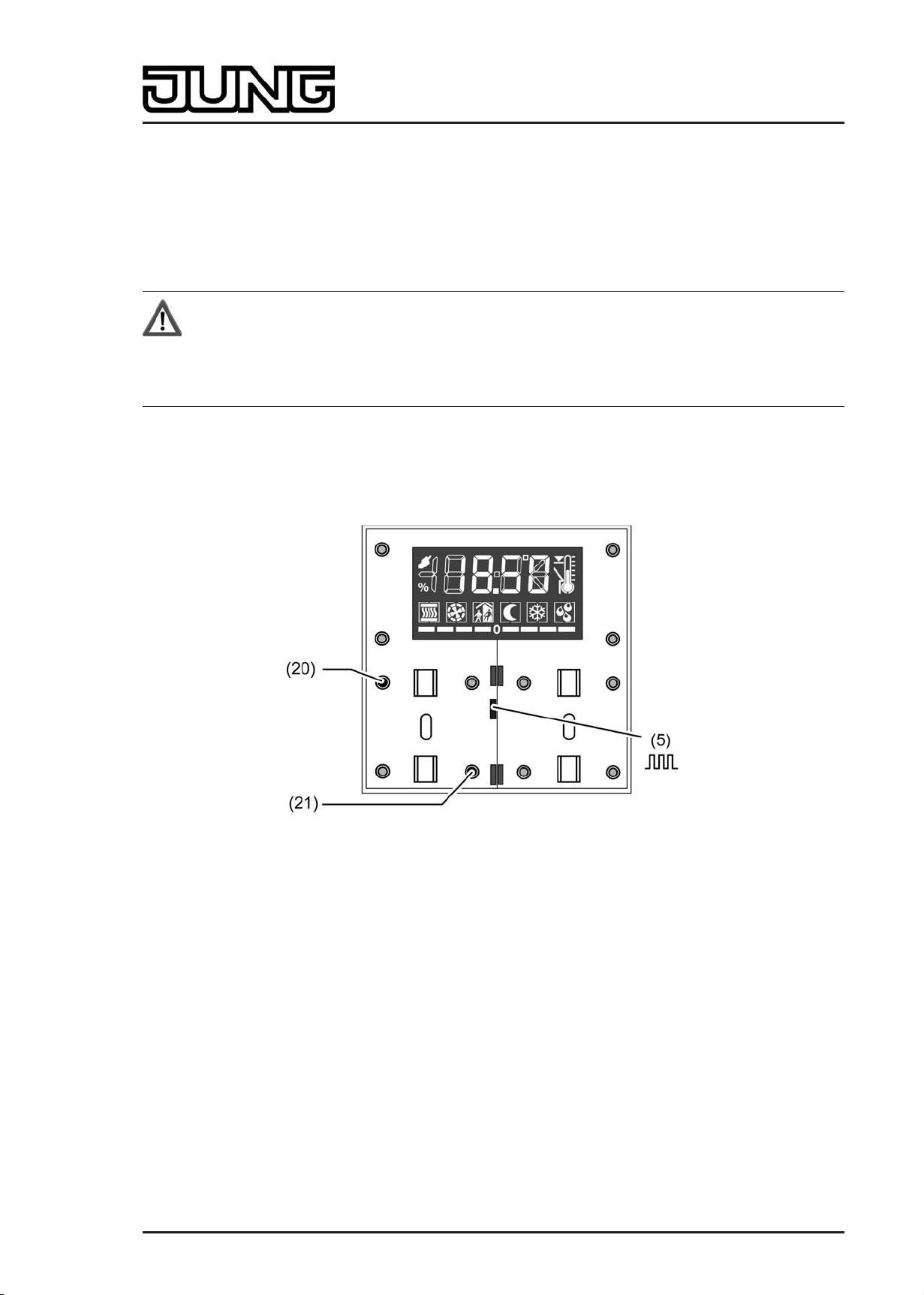
(5) Operation LED
picture 2: Device components, rear side
(6) Connection for KNX/EIB bus cable
(7) Connection for pushbutton sensor expansion module
Art.-No.: 4093 KRM TS D
Page 8 of 241
Page 9
Installation, electrical connection and operation
2.3 Fitting and electrical connection
DANGER!
Electrical shock on contact with live parts in the installation environment.
Electrical shocks can be fatal.
Before working on the device, disconnect the power supply and cover up live
parts in the working environment.
DANGER!
When mounting with 230 V devices under a common cover, e.g. socket outlets,
there is a danger of electrical shocks in the event of a fault!
Electrical shocks can be fatal.
Do not install any 230 V devices in combination with a pushbutton expansion
module under a common cover!
Snapping on the adapter frame
An adapter frame is required for the CD design. The adapter frame must be snapped onto the
continuous controller module before the device is connected and fastened to the wall.
o With the adapter frame (10) in the correct orientation, snap it from the front onto the
continuous controller module (11) (picture 3). Note marking TOP = top/front.
i If the pushbutton sensor expansion is used, the adapter frame also has to be mounted on
the pushbutton sensor expansion module.
Fitting and connecting the continuous controller module
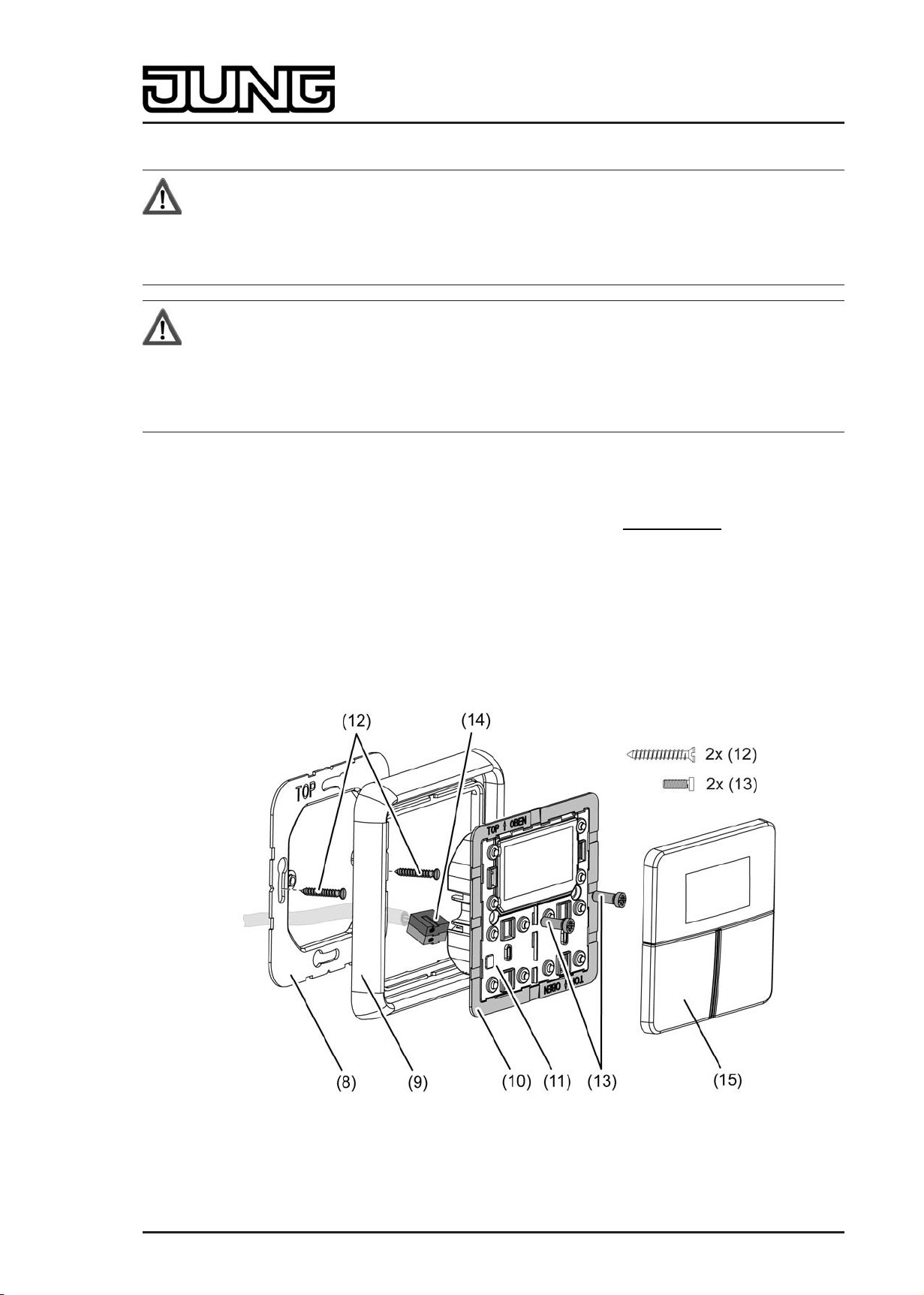
picture 3: Fitting the continuous controller module
(8) Supporting frame
Art.-No.: 4093 KRM TS D
Page 9 of 241
Page 10

Installation, electrical connection and operation
(9) Design frame
(10) Adapter frame
(11) Continuous controller module
(12) Box screws
(13) Fastening screws
(14) KNX connection terminal
(15) Design control surfaces
i Recommended installation height: 1.50 m.
i The installation of the supporting frame depends on the design used.
Supporting frame side "A" to the front for switch design ranges A, CD and FD.
Supporting frame side "B" to the front for switch design range LS.
o Mount supporting frame (8) in the right orientation on an appliance box. Note marking TOP;
marking "A" or "B" in front. Use the enclosed box screws (12).
o Position the design frame (9) on the supporting frame.
o Connect the continuous controller module (11) with KNX connection terminal (14), which is
connected to the KNX bus cable, on the rear side of the module. Run the connecting cable
downwards from the continuous controller module and then into the appliance box from the
rear.
o Push continuous controller module onto the supporting frame.
o Fasten the continuous controller module to supporting frame using the enclosed plastic
screws (13). Tighten the plastic screws only lightly.
o Before mounting the control surfaces (15), load the physical address into the device (see
chapter 2.4. Commissioning).
Art.-No.: 4093 KRM TS D
Page 10 of 241
Page 11
Installation, electrical connection and operation
Fitting and connecting continuous controller module with pushbutton sensor expansion
module
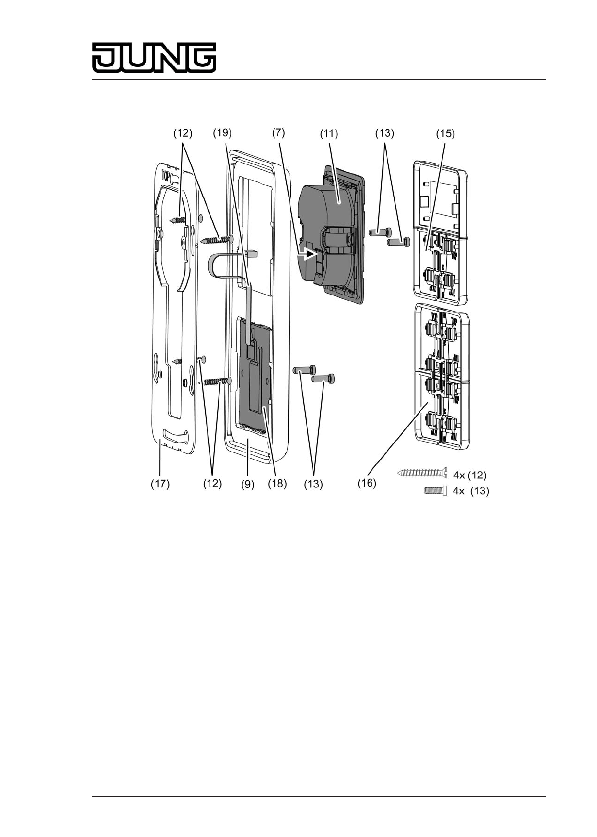
picture 4: Fitting the pushbutton sensor expansion module (example of combined fitting)
(7) Connection point in continuous controller module for connecting cable of the expansion
module
(9) Design frame
(11) Continuous controller module
(12) Box screws
(13) Fastening screws
(15) Design control surfaces for the continuous controller module
(16) Design control surfaces for the expansion module
(17) Large supporting frame for combined fitting of continuous controller module and expansion
module
(18) Pushbutton sensor expansion module
(19) Connecting cable for pushbutton sensor expansion module with plug
Art.-No.: 4093 KRM TS D
Page 11 of 241
Page 12

Installation, electrical connection and operation
i The installation of the supporting frame depends on the design used.
Supporting frame side "A" to the front for switch design ranges A, CD and FD.
Supporting frame side "B" to the front for switch design range LS.
One pushbutton sensor expansion module can be connected to each continuous controller
module. For combined fitting of an expansion module directly underneath the continuous
controller module, the large supporting frame (17) must be fitted (picture 4). The large
supporting frame is contained in the scope of supply of the pushbutton sensor expansion
module.
For combined fitting on just a single appliance box, fit the continuous controller module with the
KNX bus connection in the appliance box and countersink the fixing screws of the expansion
module in the wall, for example using Ø 6 x 10 mm boreholes. The large supporting frame can
be used as a template for this.
i Recommended installation height for the continuous controller module: 1.50 m.
The expansion module can be installed in a separate box with the extension (see
accessories) at a height of 1.10 m. The extension must be routed through a pipe. In this
installation a separate small supporting frame is used for the expansion module (included
in the scope of supply for the extension).
o For combined fitting underneath the continuous controller module: Fit large supporting
frame (17) in the right orientation on an appliance box. Note marking TOP; marking "A" or
"B" in front. Use the enclosed box screws (12).
For individual fitting of the expansion module at 1.10 m: Fit small supporting frames for the
continuous controller module and for the expansion module in the right orientation on two
appliance boxes. Note marking TOP; marking "A" or "B" in front. Use the enclosed box
screws (12).
o Position the design frame (9) on the supporting frame(s).
o For combined fitting underneath the continuous controller module: Fit pushbutton sensor
expansion module (18) in the large supporting frame. Route connecting cable (19) between
supporting frame and intermediate web.
For individual fitting of the expansion module at 1.10 m: Fit pushbutton sensor expansion
module (18) in separate small supporting frame. Guide connecting cable (19) through a
pipe into the box of the continuous controller module.
o With the plug of the connecting cable in the right orientation, insert it into the connection
point in the continuous controller module (7). When doing so, ensure that the connecting
cable is not pinched.
o Connect the continuous controller module (11) with KNX connection terminal, which is
connected to the KNX bus cable, on the rear side of the module. Run the connecting cable
downwards from the continuous controller module and then into the appliance box from the
rear.
o Push continuous controller module onto the supporting frame.
o Fasten module to supporting frame using the enclosed plastic screws (13). Tighten the
plastic screws only lightly.
o Mount the control surfaces on the pushbutton sensor expansion module (16). Before
mounting the control surfaces on the continuous controller module (15), load the physical
address into the device (see chapter 2.4. Commissioning).
Art.-No.: 4093 KRM TS D
Page 12 of 241
Page 13
Installation, electrical connection and operation
2.4 Commissioning
After the device has been connected to the bus and mounted on the wall, it can be put into
operation. Commissioning is basically confined to programming with the ETS and attaching the
decorative control surfaces.
Assignment of the physical address
DANGER!
Electrical shock when live parts are touched.
Electrical shocks can be fatal.
Before working on the device, disconnect the power supply and cover up live
parts in the working environment.
The device has an integrated bus coupling unit. It has no separate programming button or LED.
Programming mode is activated by a defined and time-delayed press on the first rocker and
signalled by the operation LED. To program the physical address, the decorative control
surfaces must not be in place on the device.
The physical address is programmed as described below...
picture 5: Buttons for activating Programming mode
o Activate Programming mode. Press button at the top left of rocker 1 (20) and keep it
depressed (picture 5). Then press the second button at the bottom right of rocker 1 (21).
Programming mode is activated. The operation LED (5) flashes quickly (approx. 8 Hz).
"Prog" is shown on the display of the device.
i Use suitable objects to push the buttons (e.g. thin screwdriver, tip of a ballpoint pen, etc.)
i To exclude any inadvertent activation of Programming mode during a 'normal' use of the
control surface in later operation, the time between the first and the second button
actuation must be at least 200 ms. Pressing both buttons simultaneously (time between
first and second actuation < 200 ms) will not result in an activation of Programming mode.
i It should be noted that the operation LED also flashes quickly in the case of a full-surface
operation of rocker 1 (see functional description). The difference from quick flashing in
programming mode is that with a full-surface operation the rocker of the LED returns to the
parameterized basic state when the buttons are released. In programming mode, flashing
continues until the operating mode is ended. The state of the LED defined by Programming
mode will always prevail.
o Program the physical address with the help of the ETS.
Art.-No.: 4093 KRM TS D
Page 13 of 241
Page 14

Installation, electrical connection and operation
The operation LED switches back to the previous status (off, on or flashing slowly).
i If Programming mode is to be activated or deactivated in a device which is already
programmed with a valid application, there is the possibility that telegrams will be
transmitted to the bus at the time the button is pressed. The telegram transmitted depends
on the push-button function programmed.
i The expansion module does not receive any physical address of its own. It is activated by
the application program loaded in the continuous controller module.
Programming the application
The application must then be programmed into the device with the help of the ETS. The ETS3.0
from version "d" onwards detects automatically whether a valid application has already been
programmed into the device before. To reduce the programming time, the ETS3 downloads the
whole application only if the device was programmed beforehand with another application or
with no application at all. In all other cases, the ETS makes a time-optimised partial download in
which only the modified data is loaded into the device. For commissioning. it is recommended to
use the ETS3.0 from Version d Patch A onwards.
i The expansion module does not receive any physical address of its own. It is activated by
the application program loaded in the continuous controller module.
Installing the decorative control surfaces
The decorative control surfaces are available as a complete set of buttons. Individual buttons or
the complete set of buttons can be replaced using buttons with symbols.
The design control surfaces are not included in the scope of supply of the continuous controller
module or the pushbutton sensor expansion module. These must be ordered specially
according to the required design.
The physical address of the continuous controller module must be programmed in the device in
advance.
o Place control surfaces on the continuous controller module in the right orientation and also
on the pushbutton sensor expansion module (if used), and snap in with a short push. Note
marking TOP.
i To simplify installation, a complete set of buttons is fitted with a mounting spider at the
factory. This mounting spider is not essential for installing the decorative control surfaces,
meaning that it is not required when adding symbol buttons to the button panel.
Art.-No.: 4093 KRM TS D
Page 14 of 241
Page 15
Installation, electrical connection and operation
2.5 Operation
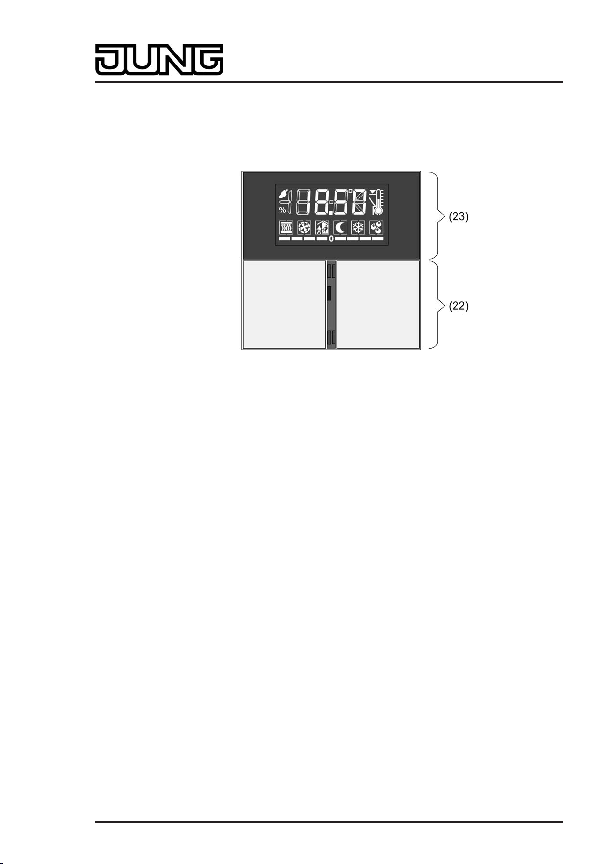
The device consists of three mechanically separate control surfaces. The control surfaces are
the design covers attached to the device with push-button elements underneath. A distinction is
made between the display control surface (23) and the control surfaces of the pushbutton
sensor function (22) (picture 6).
picture 6: Arrangement of the control surfaces on the front of the device
(22) Pushbutton sensor control surfaces (rocker 1 left / rocker 2 right) incl. 4 status LEDs
Function: Any desired pushbutton sensor function or controller operation, operation of the
second display operating level
(23) Display control surface (rocker 3)
Function: Any desired pushbutton sensor function or controller operation
The lower control surfaces (rockers 1 & 2) are allocated to the pushbutton sensor function. The
function of these rockers can also be configured in the ETS to any desired pushbutton sensor
function. Alternatively it is possible to set operation of the integrated room temperature
controller. It is also possible to activate and operate the second display operating level via
button evaluation of these surfaces (see chapter 2.5.2. Second operating level).
The display is surrounded by the upper display control surface (rocker 3). The function of this
surface can also be configured in the ETS to any desired pushbutton sensor function.
Alternatively the room temperature controller can be operated.
The pushbutton sensor function is an independent function section of the device with its own
parameter blocks in the ETS. Insofar as the control surfaces are to operate the integrated room
temperature controller, the following functions can be parameterised in the pushbutton
configuration: setpoint shift, presence button, operating mode change-over, fan control. For a
more detailed description of the operating functions, please see Chapter 4. of this
documentation.
The operation concept of a control surface can be configured in the ETS either as a rocker
function or alternatively as a push-button function. With the rocker function, one control surface
is divided into two actuation pressure points with the same basic function. In the push-button
function either a control surface is divided into 2 functionally separate actuation pressure points
(2 buttons), or a control surface is evaluated as single-surface operation (only one large button).
If a control surface is used as a single rocker function, then it is also possible to trigger special
functions using full-surface operation.
With the rocker function and the double-surface push-button function, the button arrangement
can be set either as "vertical" or as "horizontal" for each control surface. The variable
specification of the button arrangement does not, however, apply to operation of the second
display operating level via rockers 1 & 2. There the button arrangement is fixed (see chapter
2.5.2. Second operating level).
Art.-No.: 4093 KRM TS D
Page 15 of 241
Page 16
Installation, electrical connection and operation
Optionally, the number of control surfaces can be expanded to include up to 4 additional ones
by connecting an expansion module to the continuous controller module. Configuration and
commissioning of the expansion module is clearly structured and easy to perform using the
application program of the continuous controller module. The control surfaces of the expansion
module can be set in the ETS to any desired pushbutton sensor function, or also to controller
operation.
Between the lower control surfaces of the continuous controller module (rockers 1 & 2) there
are 4 red status LEDs, 2 for each rocker. These status LEDs can be internally connected to the
operating function according to the function of the rocker or pushbuttons, thus indicating the
operating status directly. They may, however, also be used for signalling completely
independent functions or be permanently on or off.
The operation LED can also signal the switching state of its own object, flash or be permanently
on or off. Besides functions that can be set using the ETS, the operation LED also indicates that
the device is in the programming mode for commissioning or diagnosis purposes.
2.5.1 Basic display
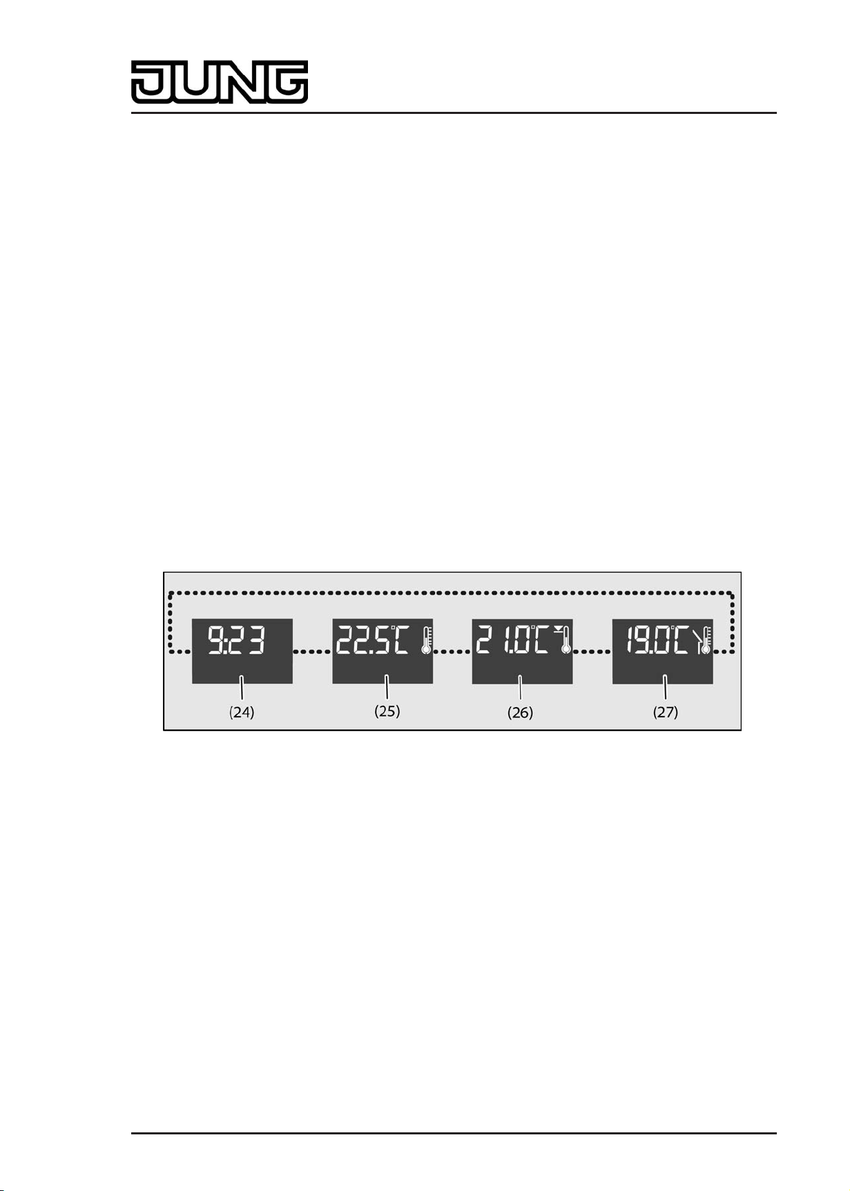
During device operation, the basic display of the display can show up to four different display
functions. This means that is possible to display the time, the setpoint temperature, the actual
temperature (room temperature) or the outdoor temperature (picture 7). The information is
shown separately on the display. It is possible to change over between the information
automatically after set times or in a controlled manner by pressing a button on the device.
These properties, and the actually visible display information, are configured in the ETS before
the device is commissioned (see chapter 4.2.4.5. Display).
picture 7: Possible display information of the basic display
(24) Time display (with flashing seconds mark ":")
(25) Actual temperature display (room temperature)
(26) Setpoint temperature display
(27) Outdoor temperature display
i The temperatures can be displayed in °C or alternately in °F. The display format can be
configured in common for all temperature values in the ETS.
Art.-No.: 4093 KRM TS D
Page 16 of 241
Page 17
Installation, electrical connection and operation
2.5.2 Second operating level
The second operating level makes it possible to make various basic settings on the unit locally
without using the ETS. In order to avoid the unintentional disruption of essential functions,
access to individual settings or to the entire second operating level can be prevented via the
parameterisation in the ETS. An active button disable also disables access to the second
operating level.
Calling up the second operating level
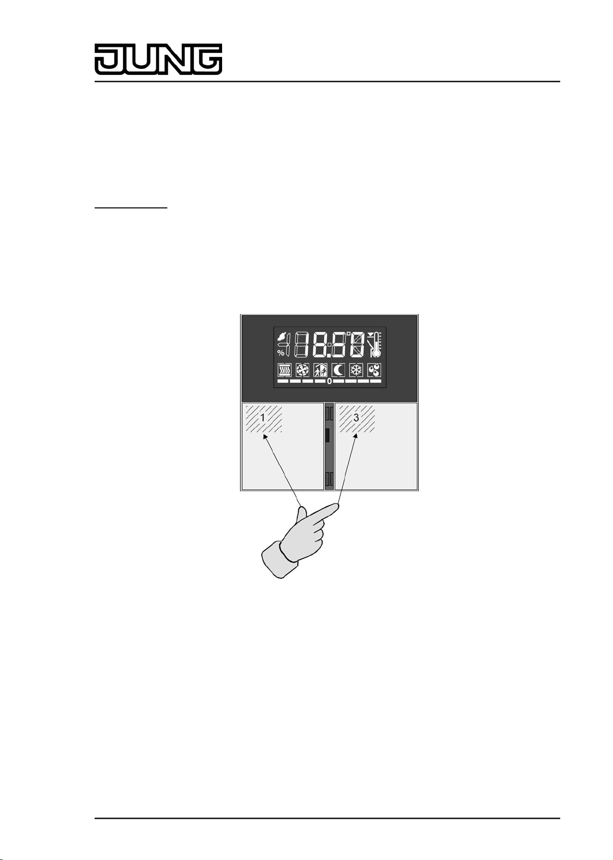
The second operating level is called up by pressing buttons 1 and 3 on the device
simultaneously(picture 8). It must be ensured here that the control surfaces are pressed at the
upper left corner in order to be independent of the configured button arrangement.
The device leaves the second operating level again when buttons 1 and 3 are pressed again
simultaneously. Depending on the setting of the ETS parameter "Save changes after manual
exit?" all settings that have been made are saved or discarded in this case. The parameters
"Automatic exit of the second operating level", "Time until automatic exit" and "Save changes?"
define whether the device terminates the second operating level automatically if no entries are
made, and whether in this case all of the changed settings are saved or discarded (see "Exiting
the second operating level").
picture 8: Button combination to call up the second operating level
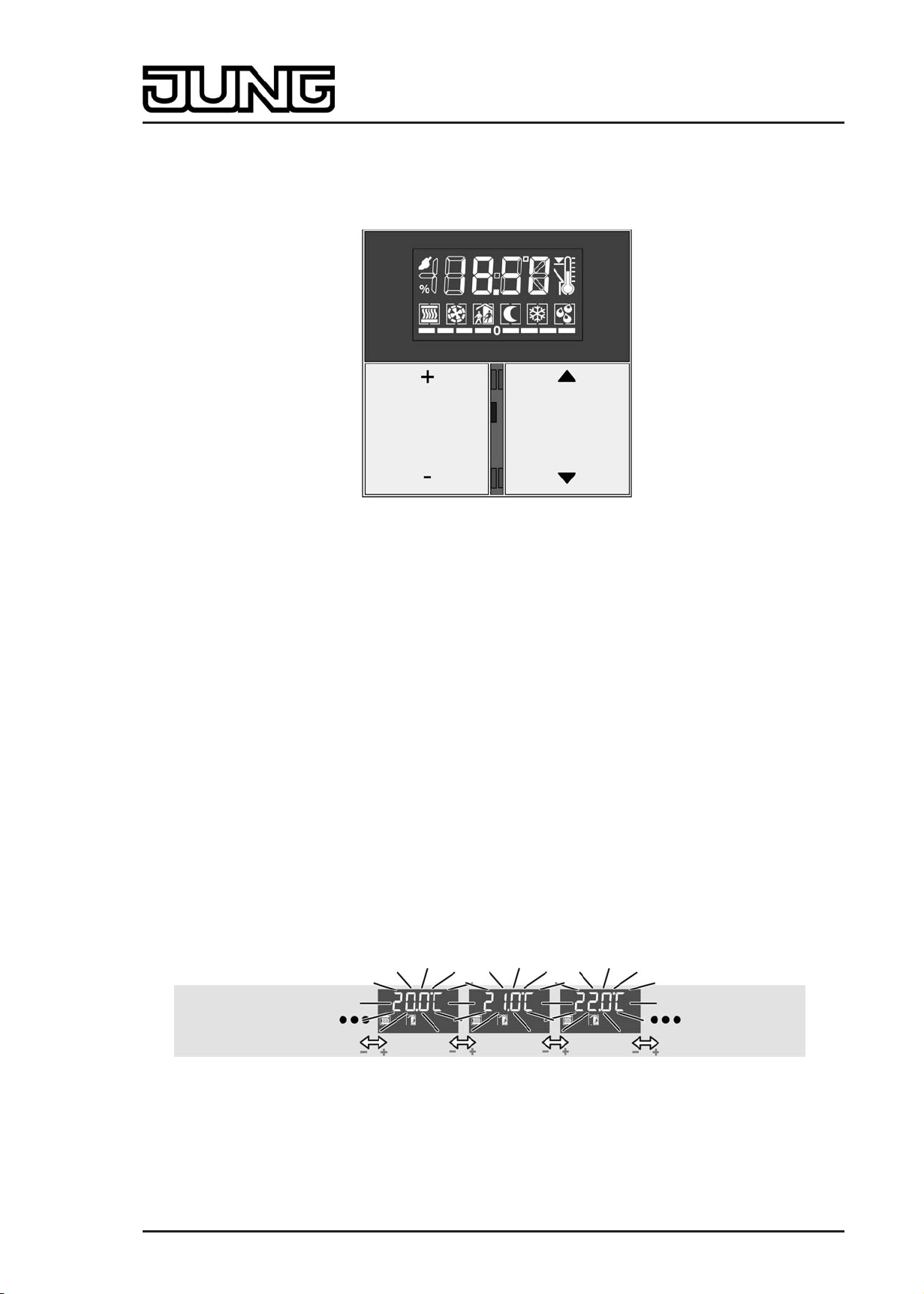
Operation in the second operating level
The settings in the second operating level are organised in a ring-shaped menu. This is shown
in the display. Selection and settings are performed using the 1...4 buttons of the device
(picture 9). Within the second operating level the button arrangement of the control surfaces is
preset to "top / bottom" independently of the ETS configuration, and cannot be changed.
Moreover, buttons 1...4 are always available for operation of the second operating level,
independently of any single-surface operation configured in the ETS.
The four buttons have the following functions...
Button 1: + change-over or value change in positive direction
Button 2: - change-over or value change in negative direction
Button 3: n Jump to the previous menu entry
Button 4: o Jump to the next menu entry
Art.-No.: 4093 KRM TS D
Page 17 of 241
Page 18
Installation, electrical connection and operation
i Continuous adjustment of the value settings is possible if buttons 1 or 2 are held in the
depressed position.
picture 9: Button assignment for operation in the second operating level
Configuration in the ETS offers various options for influencing the entries that are visible and
changeable in the menu...
1. If entries are configured via parameterisation as "hidden", they do not appear in the menu.
This setting is performed in the ETS separately for various menu entries in the parameter node
"General -> Second operating level" Some entries are always visible and can thus not be
configured as invisible in the ETS. When the device functions as a controller extension,
controller settings (setpoint temperatures, setpoint shifting, operating mode, fan control) are
fundamentally not accessible in the second operating level.
2. The setpoint temperatures of the continuous controller can either be changeable, or can
alternatively only show the current value and thus not be editable. This setting is performed in
the ETS in the parameter node "Room temperature control -> Controller general -> Second
operating level".
The menu entry that is shown as the first entry when the second operating level is called up can
be selected in the ETS using the parameter "First menu item in second operating level". The
sequence of the subsequent entries is then fixed as shown below.
The following menu functions can be called up in the second operating level, if not explicitly
disabled in the ETS. The symbols shown in the display indicated which function or which
temperature value is displayed or set.
Setting the basic temperature ("Continuous controller" menu):
picture 10: Setting the basic temperature
The + and - buttons can be used to adjust the basic temperature in increments of +/- 1 K. The
symbols ó and ÿ light up in the display. The basic temperature is displayed flashing as an
absolute value in °C or °F (parameter-dependent).
The basic temperature designates the comfort setpoint temperatures for heating and cooling,
depending on the configured operating mode. With "Heating only" it sets the setpoint
Art.-No.: 4093 KRM TS D
Page 18 of 241
Page 19
Installation, electrical connection and operation
temperature for comfort heating directly. With "Cooling only", on the other hand, it sets the
setpoint temperature for comfort cooling. With "Heating and cooling" the basic setpoint sets the
setpoint temperature for heating directly or indirectly depending on the deadband position. The
setpoint temperature for cooling is then derived from this, taking the deadband into account.
(see chapter 4.2.4.2.5. Temperature setpoints)
The menu entry "Basic temperature" is visible as an option as a component of the "Continuous
controller" menu. The editing function can be disabled separately. This menu is not accessible
in controller extensions.
Setting the setpoint temperature "Lowering for standby mode, heating" ("Continuous controller"
menu):
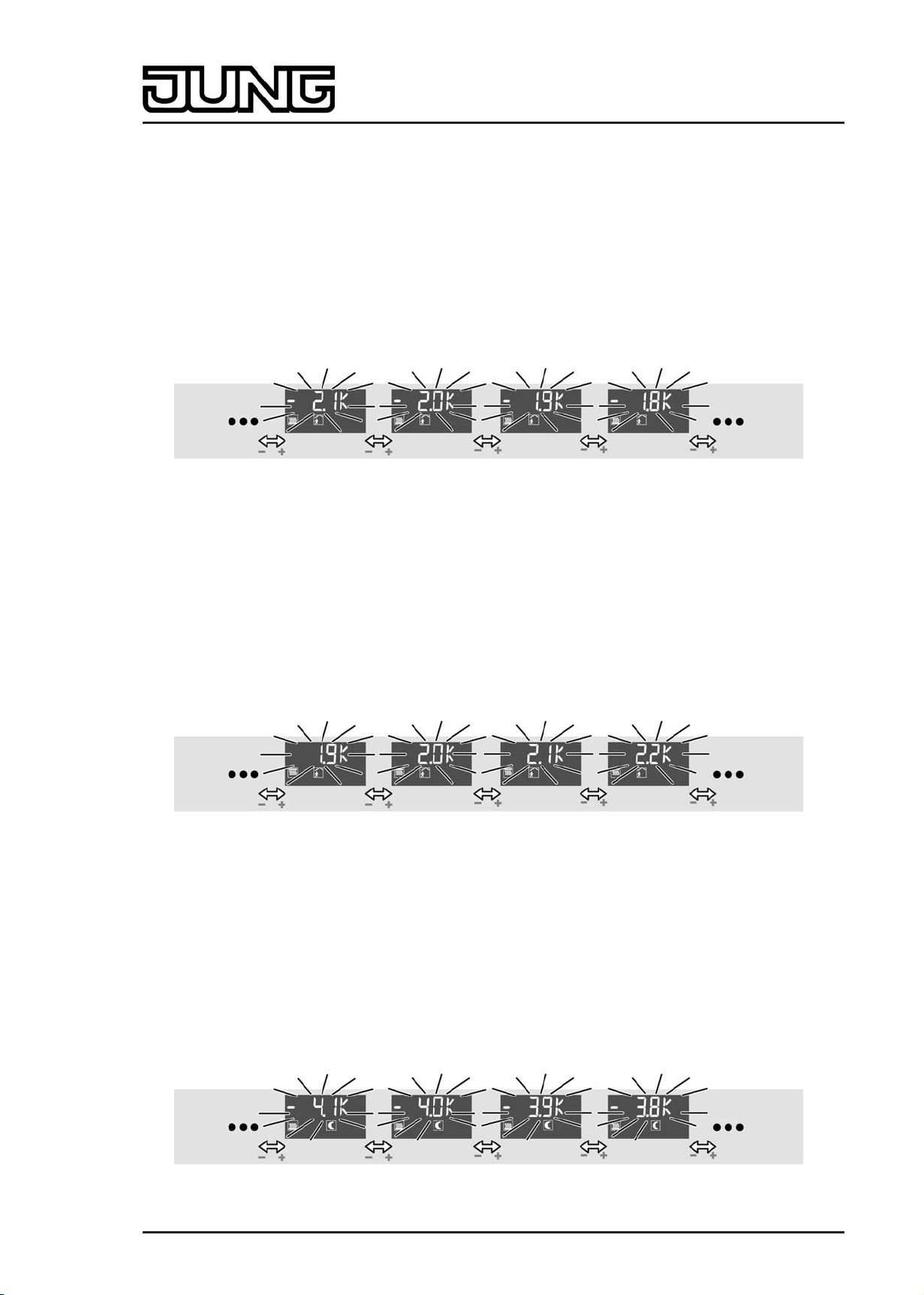
picture 11: Setting the setpoint temperature "Lowering for standby mode, heating"
The + and - buttons can be used to adjust the temperature decrease for standby mode for
heating with an increment of +/- 0.1 K. The symbols ô and â light up in the display. The
temperature decrease is displayed flashing as a relative value in K.
The menu entry "Setpoint temperature lowering standby" is visible as an option as a component
of the "Continuous controller" menu. The editing function can be disabled separately. This menu
is not accessible in controller extensions.
Setting the setpoint temperature "Raising for standby mode, cooling" ("Continuous controller"
menu):
picture 12: Setting the setpoint temperature "Raising for standby mode, cooling"
The + and - buttons can be used to adjust the temperature increase for standby mode for
cooling with an increment of +/- 0.1 K. The symbols ô and è light up in the display. The
temperature increase is displayed flashing as a relative value in K.
The menu entry "Setpoint temperature raising standby" is visible as an option as a component
of the "Continuous controller" menu. The editing function can be disabled separately. This menu
is not accessible in controller extensions.
Setting the setpoint temperature "Lowering for night mode, heating" ("Continuous controller"
menu):
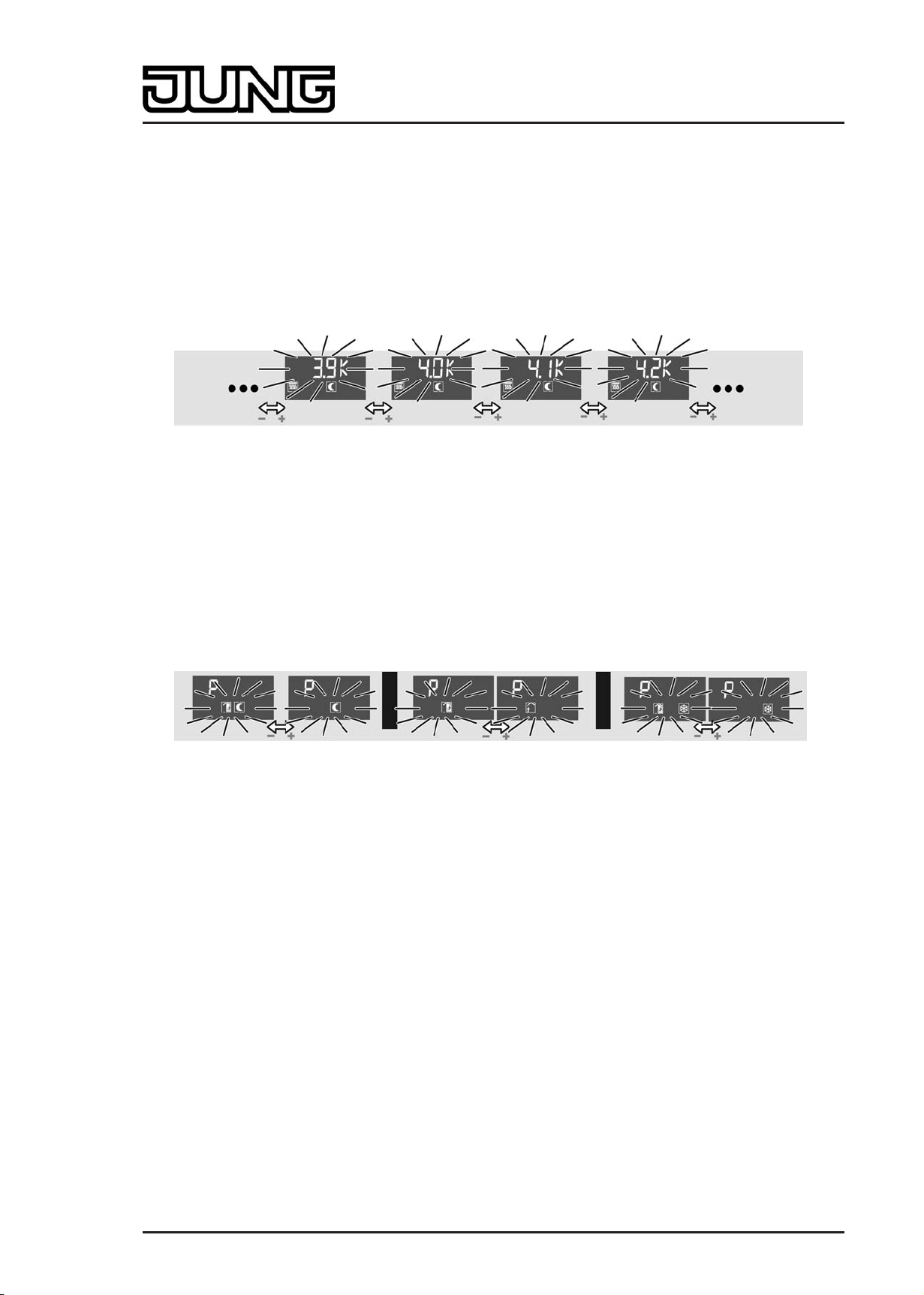
picture 13: Setting the setpoint temperature "Lowering for night mode, heating"
Art.-No.: 4093 KRM TS D
Page 19 of 241
Page 20
Installation, electrical connection and operation
The + and - buttons can be used to adjust the temperature decrease for night mode for heating
with an increment of +/- 0.1 K. The symbols õ and â light up in the display. The temperature
decrease is displayed flashing as a relative value in K.
The menu entry "Setpoint temperature lowering night" is visible as an option as a component of
the "Continuous controller" menu. The editing function can be disabled separately. This menu is
not accessible in controller extensions.
Setting the setpoint temperature "Raising for night mode, cooling" ("Continuous controller"
menu):
picture 14: Setting the setpoint temperature "Raising for night mode, cooling"
The + and - buttons can be used to adjust the temperature increase for night mode for cooling
with an increment of +/- 0.1 K. The symbols õ and è are illuminated in the display. The
temperature increase is displayed flashing as a relative value in K.
The menu entry "Setpoint temperature raising night" is visible as an option as a component of
the "Continuous controller" menu. The editing function can be disabled separately. This menu is
not accessible in controller extensions.
Setting presence mode ("Presence" menu):
picture 15: Setting presence mode
A "P" is shown in the display to indicate that the presence mode can be edited. The symbols
additionally shown in the display identify the active operating mode of the internal room
temperature controller. Depending on this, presence mode can be adjusted as follows using the
+ and - buttons...
"Comfort" operating mode active:
No setting of presence mode is possible. The ó symbol lights up statically.
"Standby" operating mode active:
The buttons + or - can be used to change over the operating mode between Comfort ó and
Standby ô. In each case, the symbols activated by the Presence operating mode flash.
"Night" operating mode active:
The buttons + or - can be used to change over the operating mode between Night õ and
Comfort extension óõ. In each case, the symbols activated by the Presence operating mode
flash.
"Frost/heat protection" operating mode active:
The buttons + or - can be used to change over the operating mode between Frost/heat
protection ö and Comfort extension óö. In each case, the symbols activated by the Presence
operating mode flash.
i The comfort extension cannot be activated using the presence function in the second
operating level if the frost/heat protection has been activated via the window status!
Art.-No.: 4093 KRM TS D
Page 20 of 241
Page 21
Installation, electrical connection and operation
i In the second operating level, presence mode and operating mode (see "Setting the
operating mode" below) may never be changed at the same time before a "save"
command. Otherwise the presence status is always reset, and thus the manual setting may
not be applied. If the controller operating mode and the presence mode have to be
changed, first the operating mode has to be changed and the setting has to be saved. Only
after that is it possible to change the presence mode and save this setting by calling up the
second operating level again.
The menu entry "Presence" is visible as an option. This menu is not accessible in controller
extensions.
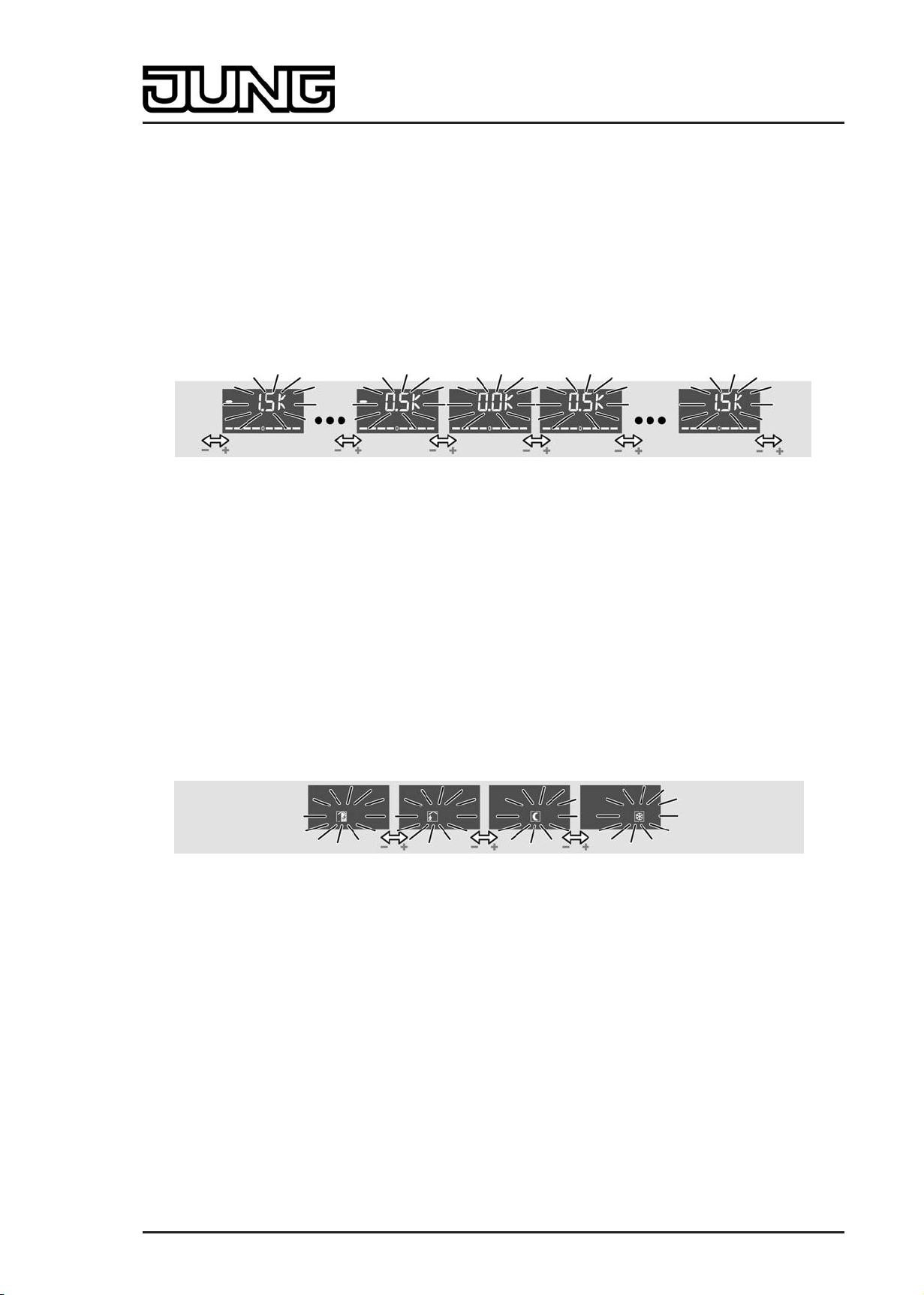
Setting the setpoint shift ("Setpoint shift" menu):
picture 16: Setting the setpoint shift
The menu entry for setpoint shifting is indicated in the display by the bar scale "- - - - 0 - - - -".
The buttons + and - can be used to adjust the basic setpoint shift by up to 4 levels. Here the
shift is shown in the display as a relative numeric value in kelvin (K)
The increment of the shift depends on the ETS parameter "Increment of the 4-level setpoint
shift" in the parameter branch "Room temperature controller -> Controller general -> Setpoints".
i A setpoint shift cannot be saved when the second operating level is exited if the frost/heat
protection is activated in the controller! In this case the settings of the setpoint shift in the
second operating level are lost.
The menu entry "Setpoint shift" is visible as an option. This menu is not accessible in controller
extensions.
Setting the operating mode ("Operating mode" menu):
picture 17: Setting the operating mode
The buttons + and - can be used to adjust the controller operating mode. The symbol for the
active operating mode flashes in the display. The modes that can be set are "Comfort" ó,
"Standby" ô, "Night" õ and "Frost/heat protection" ö.
It should be noted that a set operating mode with a low priority cannot be activated immediately
when the second operating level is exited if an operating mode with a higher priority (e.g. frost
protection via window status) has been specified by the controller (see chapter 4.2.4.2.4.
Operating mode change-over). The operating mode set in the second operating level is only
accepted by the controller when the operating mode with a higher priority has been terminated
and in the meantime no other operating mode specification with a higher priority has been
performed (e.g. via operation of a pushbutton sensor or via communication objects).
The menu entry "Operating mode" is visible as an option. This menu is not accessible in
controller extensions.
Art.-No.: 4093 KRM TS D
Page 21 of 241
Page 22
Installation, electrical connection and operation
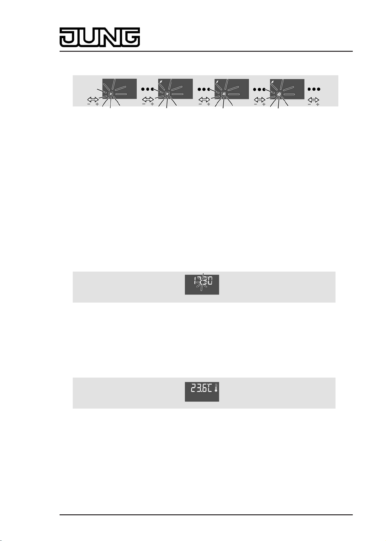
Fan control ("Fan levels" menu):
picture 18: Fan controller
The + and - buttons can be used to influence the fan operating mode (automatic / manual
mode). In manual mode it is possible to change over the fan level independently of the
controller command values (see chapter 4.2.4.2.8. Fan controller).
When the menu entry "Fan levels" is called up, the fan symbol in the display flashes, and
indicates the current fan level by means of the illuminated arc segments ( ì, í, î etc.). If no
arc segment is illuminated, the fan is switched off. The display also shows whether the fan
controller is in automatic or manual operation. In manual operation the Ü symbol is also
illuminated. The number of illuminated arc segments depends on the number of fan levels
configured.
i In fan control in the second operating level the fan level and automatic mode can be set
directly without taking into account the specific settings of the fan controller (Parameter
"Fan level on change-over to manual", the switch-on level or fan run-on times).
The menu item "Fan levels" is visible as an option, but only if the fan control is also enabled in
the controller for the ETS. This menu is not accessible in controller extensions.
Indicating the time:
picture 19: Indicating the time
Only indication of the current time. No adjustment possibility.
The menu entry "Time" is visible as an option.
Indication of actual temperature:
picture 20: Indication of actual temperature
Only Indication of the current room temperature No adjustment possibility.
The menu entry "Actual temperature" is visible as an option.
Indication of setpoint temperature:
Art.-No.: 4093 KRM TS D
Page 22 of 241
Page 23
Installation, electrical connection and operation
picture 21: Indication of setpoint temperature
Only indication of the current setpoint temperature. No adjustment possibility.
The menu entry "Setpoint temperature" is visible as an option.
Indicating the outdoor temperature:
picture 22: Indicating the outdoor temperature
Only indication of the current outdoor temperature No adjustment possibility.
The menu entry "Outdoor temperature" is visible as an option.
Setting the display contrast:
picture 23: Setting the display contrast
Illuminate all elements of the display. The buttons + and - can be used to adjust the display
contrast.
The menu item "Display contrast" is always visible.
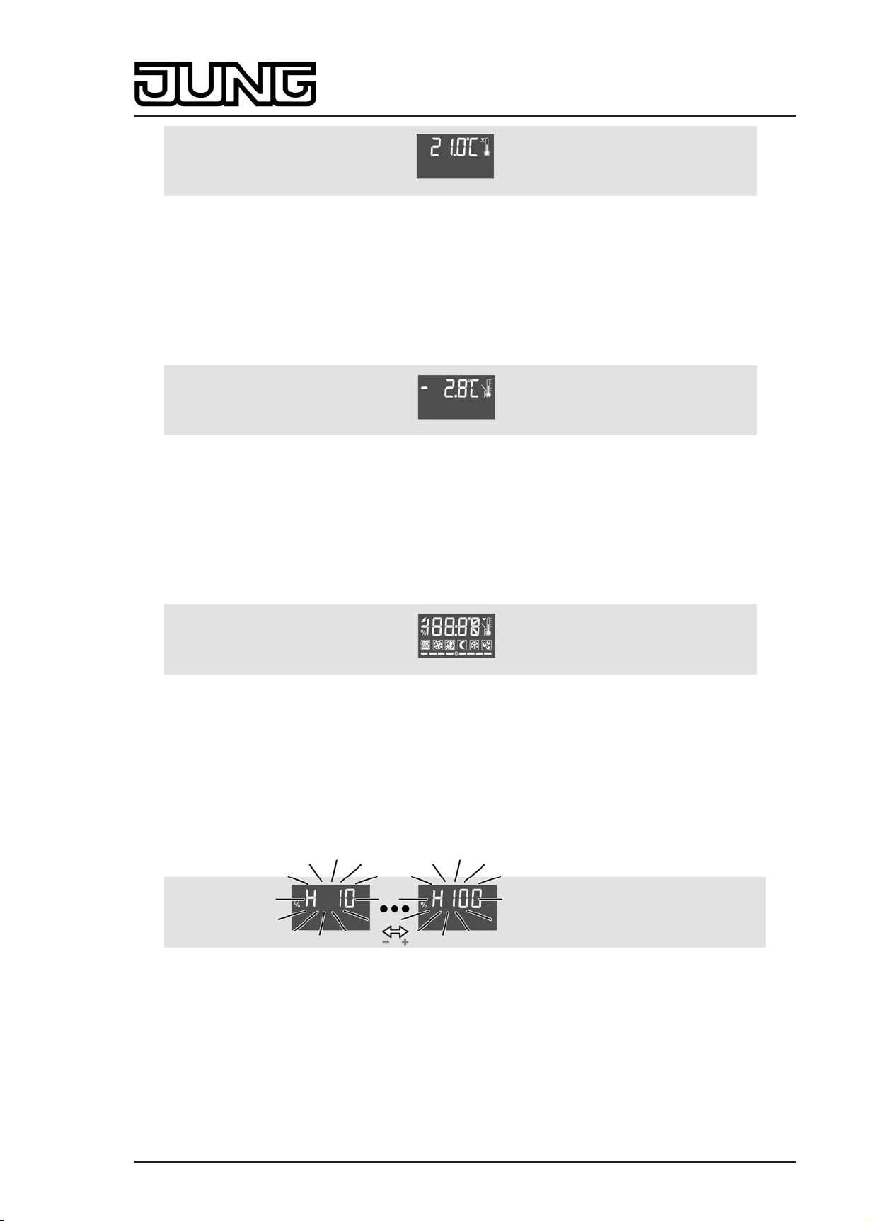
Setting the display brightness:
picture 24: Setting the display brightness
"H" and the brightness value of the backlighting are displayed in the backlighting. The buttons +
and - can be used to adjust the brightness of the display in the range from 10 to 100%. For
additional notes about control of the backlighting, via the second operating level, please see the
chapter "Display control" (see page 165-166).
The menu item "Display brightness" is always visible.
Exiting the second operating level by pressing Save:
Art.-No.: 4093 KRM TS D
Page 23 of 241
Page 24

Installation, electrical connection and operation
picture 25: Exiting the second operating level by pressing Save:
"OK" is displayed. The buttons + or - can be used to exit the second operating level with a
"save" command (see "Exiting the second operating level").
This option is always visible.
Exiting the second operating level without saving:
picture 26: Exiting the second operating level without saving
"ESC" is shown on the display. The buttons + or - can be used to exit the second operating level
without saving the settings (see "Exiting the second operating level").
This option is always visible.
i All menu entries are displayed or not depending on the configuration of the ETS. If, for
example, the controller is parameterised only for heating, no setpoints for cooling can be
displayed or set in the menu. When the device functions as a controller extension,
controller settings (setpoint temperatures, setpoint shifting, operating mode, fan control) are
fundamentally not accessible in the second operating level.
If an entry has been parameterised as the first menu item in the ETS that is not accessible
at all due to the other settings, the first possible entry is displayed according to the defined
menu sequence (see above).
i When a menu entry is shown on the display, the setting currently valid in the controller is
identified using the symbols or the display value, if the setting has not already been
changed previously in the second operating level. If the setting has already been changed
and not yet accepted validly (see "Exiting the second operating level"), the last manual
setting will be shown on the display, and not the real state of the controller.
Exiting the second operating level
Settings that have been made in the second operating level are only accepted validly in the
device when the operating level is exited with a "Save" command. It is possible to discard
settings by exiting the second operating level without a "Save" process. When exiting the
second operating level, a distinction is made among the following cases...
- Exiting by means of button combination: The second operating level is exited by pressing
buttons 1 and 3 on the device simultaneously (picture 8). Here the parameter "Save
changes after exiting with button combination?" defines whether the settings are saved or
not when the second operating level is exited using the button combination.
Art.-No.: 4093 KRM TS D
Page 24 of 241
Page 25

Installation, electrical connection and operation
- Automatic exiting: Automatic exiting of the second operating level can optionally be
configured in the ETS using the parameter of the same name in the parameter branch
"General -> Second operating level". In this case the device leaves the second operating
level when no additional operation takes place after the last push-button operation within
the "Time until automatic exit" configured in the ETS. With automatic exiting it is also
possible to define with the parameter "Save changes after automatic exiting?" whether the
settings are saved or not.
- Exiting with "OK": In the second operating level the menu item "OK" can be selected with
the n or o buttons. The buttons + or - can then be used to exit the second operating level.
All settings are always saved in this case!
- Exiting with "ESC": In the second operating level the menu item "ESC" can be selected
with the n or o buttons. The buttons + or - can then be used to exit the second operating
level. In this case the settings are not saved and are discarded!
Art.-No.: 4093 KRM TS D
Page 25 of 241
Page 26

Technical data
3 Technical data
General
Safety class III
Mark of approval KNX
Ambient temperature -5 ... +45 °C
Storage/transport temperature -25 ... +70 °C
KNX/EIB supply
KNX medium TP 1
Commissioning mode S mode
Rated voltage KNX DC 21 V ... 32 V SELV
Power consumption KNX typical 150 mW
Connection mode KNX Connection terminal
Art.-No.: 4093 KRM TS D
Page 26 of 241
Page 27

Software specification
4 Software description
4.1 Software specification
ETS search paths: - Heating, A/C, Ventilation / Valve / Room controller display
compact module
- Push-button / Push-button, general / Room controller display
compact module
BAU used: FZE 1066 + µC
KNX/EIB type class: 3b device with cert. Physical layer + stack
Configuration: S mode standard
PEI type: "00"
PEI connector: No connector
Application program:
No. Short description Name Version from mask
Hex
/ "0"
Dec
version
1 Multifunctional room temperature
controller / pushbutton sensor
application:
Up to 3 control surfaces on the
continuous controller module for the
pushbutton sensor function and for
operation of the integrated room
temperature controller. Can be
expanded to include 4 additional
control surfaces using an expansion
module.
Continuous
controller module
3gang 146A11
1.1
for ETS3.0d
onwards
705
Art.-No.: 4093 KRM TS D
Page 27 of 241
Page 28

Software "Continuous controller module 3gang 146A11"
Scope of functions
4.2 Software "Continuous controller module 3gang 146A11"
4.2.1 Scope of functions
General functions
- The operation LED can be permanently on or off or alternatively be switched via a
communication object.
- Internal clock to indicate the time on the device display. The time information is made
available to the device using a communication object (e.g. by a KNX/EIB timer switch).
Automatic time request possible after a device restart.
- LC display with switchable backlighting. On the display, icons signal various operating
states of the integrated room temperature controller or the controller extension. In addition,
up to four display functions (time, actual temperature, setpoint temperature, outdoor
temperature) can be shown on the display either alternating over time or controlled by
pressing a button.
- Integrated scene control. Internal storage of up to eight scenes with eight output channels,
recall of internal scenes by means of a presettable scene number, selection of object types
for the output channels; for each scene, the storage of the individual output values and the
transmission of the output values can be permitted or inhibited; the individual channels can
be delayed during scene recall; as scene extension, 64 scenes can be recalled and stored.
- The number of control surfaces can be expanded using a pushbutton sensor expansion
module.
Functions of the integrated pushbutton sensor
- Each control surface can either be used as a single rocker or as two independent buttons.
- For push-button function either double-surface or single-surface principle.
- Each rocker can be used for the functions 'switching', 'dimming', 'Venetian blind', '1 byte
value transmitter', '2-byte value transmitter', 'scene extension' and '2-channel operation'.
- Each button can be used for the functions 'switching', 'dimming', 'Venetian blind', '1 byte
value transmitter', '2-byte value transmitter', 'scene extension' and '2-channel operation',
'controller extension', 'fan controller', 'controller operating mode', 'setpoint shift', and
'change in the display reading'. The 'fan controller', 'controller operating mode' and 'setpoint
shift' functions are used to operate the integrated room temperature controller.
- 2-channel operating function: each rocker or each button can be set for controlling two
independent channels. This means that only one button-press is enough to transmit up to
two telegrams to the bus. The channels can be configured independently of one another for
the functions Switching, Value transmitter (1 byte) or Temperature value transmitter (2
bytes).
- For the rocker functions Dimming, Venetian blind (operation concept "Long – Short or
Short")' and 2-channel operation, full-surface rocker actuation can also be evaluated. With
full-surface rocker operation, switching telegrams and scene recall requests can be
triggered on the bus in addition to and independently of the configured rocker function.
- The switching function permits the following settings: reaction after pressing and/or
releasing, switch on, switch off, and toggle.
- The dimming function permits the following settings: times for short and long actuation,
dimming in different levels, telegram repetition on long press, transmission of stop telegram
after end of press.
- The shutter control permits the following settings: four different operation concepts with
times for short and long press and slat adjustment.
- The 1-byte and 2-byte value transmitter function permits the following settings: selection of
the value range (0 … 100 %, 0 … 255, 0 … 65535, 0 … 1500 lux, 0 … 40 °C), value on
button-press, value change on sustained button-press with different level sizes, optional
overflow on reaching the end of a value range.
- The controller extension function permits the following settings to operate an external room
temperature controller: operating mode change-over with normal and high priority, defined
selection of an operating mode, change between different operating modes, change of
presence status, setpoint shift.
Art.-No.: 4093 KRM TS D
Page 28 of 241
Page 29

Software "Continuous controller module 3gang 146A11"
Scope of functions
- Each control surface has two status LEDs (exception: display control surface). When a
status LED is internally connected with the rocker or the button, it can signal a button-press
or the current status of a communication object. The status indication can also be in
inverted form. When a status LED is not dependent on the rocker or button, it can be
permanently on or off, indicate the status of an independent communication object, the
operating state of a room temperature controller or the result of a comparison between
signed or unsigned 1 byte values.
- The rockers or buttons can be disabled via a 1-bit object. The following settings are
possible: polarity of the disabling object, behaviour at the beginning and at the end of
disabling. During an active disable, all or some of the rockers / buttons can have no
function, can perform the function of a selected button or execute one of two presettable
disabling functions.
- A delay to the automatically transmitted communication objects of the controller external
after a device reset can be configured. The delay time is automatically produced by the
subscriber address (physical address).
- All LEDs of the pushbutton sensor can flash simultaneously in the event of an alarm
message. The following settings are possible: Value of alarm message object for the states
alarm / no alarm, alarm acknowledge by pressing a button, transmission of the
acknowledge signal to other devices.
Functions of the integrated room temperature controller
- Various operating modes can be activated: Comfort, Standby, Night and Frost/heat
protection
- Each operating mode can be assigned its own temperature setpoints (for heating and/or
cooling).
- Comfort extension possible using presence button in Night or Frost/heat protection mode.
Configurable duration of the comfort extension.
- Operating mode change-over via 1-byte object according to KONNEX or using up to four
individual 1-bit objects.
- Frost/heat protection change-over via window status.
- Indication of room temperature controller information via the device display
- Function buttons to operate the controller (setpoint shift and second operating level, for
example to change the setpoint temperatures).
- Operating modes "Heating", "Cooling", "Heating and cooling" each with or without
additional level.
- Various control types can be configured for each heating or cooling level: PI feedback
control (permanent or switching PWM) or 2-point feedback control (switching).
- Control parameter for PI controller (if desired: proportional range, reset time) and 2-point
controller (hysteresis) adjustable.
- The temperature setpoints for the additional level are derived via a configurable level offset
from the values of the basic level.
- Automatic or object oriented change-over between "Heating" and "Cooling".
- Temporary setpoint shifting or permanent setpoint shifting through operation of the function
buttons on the device or via communication objects possible (e.g. using a controller
extension). Indication of the setpoint shift on the device display by means of a line graphic.
- Complete (1-byte) or partial (1-bit) status information configurable and transmissible on the
bus via objects.
- Deactivating the feedback control or the additional level possible using separate 1-bit
objects.
- Internal and external temperature sensor for room temperature measurement possible.
- Configurable internal to external determination of measured value and enabled external
sensor for room temperature measurement. Settable polling time of the external
temperature sensor.
- The room temperature measurement (actual value) can be adjusted separately for the
internal and external sensor using parameters.
- The actual and setpoint temperatures can be output on the bus if a configurable deviation
is detected (also periodically).
- Separate or shared command value output in heating and cooling mode. This produces
one or two command value objects for each level.
- Normal or inverted command value output configurable
- Automatic transmission and cycle time for command value output configurable
Art.-No.: 4093 KRM TS D
Page 29 of 241
Page 30

Software "Continuous controller module 3gang 146A11"
Scope of functions
- Floor temperature limit possible in heating mode. Thus temperature-controlled switch-off of
a floor heater as protective function.
- Setpoint temperature limit possible in cooling mode. If necessary, the controller limits the
setpoint temperature to specific values and prevents an adjustment beyond statutory limits.
Functions of the integrated controller extension
- Alternatively to the function of the room temperature controller, the extension mode can be
activated. This allows control of an external room temperature controller.
- Full control of the controller (operating modes, presence functions and setpoint shift).
- Full-featured indication of the controller status on the display of the extension (heating /
cooling reporting, setpoint shift, room temperature, setpoint temperature and current
operating mode).
- Room temperature measurement also possible on the extension.
Art.-No.: 4093 KRM TS D
Page 30 of 241
Page 31

Software "Continuous controller module 3gang 146A11"
Notes on software
4.2.2 Notes on software
ETS configuration and commissioning
For configuration and commissioning of the device, at least ETS3.0 from Version d Patch A
onwards is required. Advantages with regard to downloading (significantly shorter loading times)
and parameter programming using the integrated database plug-in can be expected only if this
ETS version or later versions are used.
The necessary product database is offered in the *.VD4 format. No product database is
available for ETS2 and older versions of ETS3.
Art.-No.: 4093 KRM TS D
Page 31 of 241
Page 32

Software "Continuous controller module 3gang 146A11"
4.2.3 Object table
Number of communication objects: 112
Number of addresses (max): 254
Number of assignments (max): 255
Dynamic table management Yes
Maximum table length 509
4.2.3.1 Object table, pushbutton sensor function section
Objects for rocker or push-button function (basic or module control surfaces)
Function: Switching
Object table
Object
0
h
Function
Switching
Name
T.rocker/T.button 1
1,2
Type
1-bit
DPT
1.xxx
Flag
C, W, T,
(R)
Description 1-bit object for the transmission of switching telegrams (ON, OFF).
Function: Dimming
Object
0
h
Function
Switching
Name
T.rocker/T.button 1
1,2
Type
1-bit
DPT
1.xxx
Flag
C, W, T,
(R)
Description 1-bit object for the transmission of switching telegrams (ON, OFF).
Function: Dimming
Object
18
h
Function
Dimming
Name
T.rocker/T.button 1
1,2
Type
4-bit
DPT
3.007
Flag
C, W, T,
(R)
Description 4-bit object for the transmission of relative dimming telegrams.
3
3
3
1: The number of rockers or buttons depends on the planned pushbutton sensor variant and the
pushbutton sensor expansion module. Mixed operation of rocker or push-button functions in a
pushbutton sensor is possible on the basic module and the expansion module.
2: The objects have been described for rocker 1 or button 1 as an example. The objects for the
rockers/buttons of the basic device and the module rockers/buttons are defined in the same way
by shifting the object number and changing the object name.
3: For reading, the R-flag must be set. The last value written to the object via the bus or by the
device will be read.
Art.-No.: 4093 KRM TS D
Page 32 of 241
Page 33

Function: Venetian blind
Software "Continuous controller module 3gang 146A11"
Object table
Object
0
h
Function
Short-time operation
Name
T.rocker/T.button 1
1,2
Type
1-bit
DPT
1.007
Flag
C, -, T, (R)
3
Description 1-bit object for the transmission of telegrams with which a Venetian blind or
shutter drive motor can be stopped or with which the blind slats can be
adjusted by short-time operation.
Function: Venetian blind
Object
18
h
Function
Long-time operation
Name
T.rocker/T.button 1
1,2
Type
1-bit
DPT
1.008
Flag
C, W, T,
3
(R)
Description 1-bit object for the transmission of telegrams with which a Venetian blind or
shutter drive motor can be can be moved upwards or downwards.
Function: 1-byte value transmitter
Object
0
h
Function
Value
Name
T.rocker/T.button 1
1,2
Type
1-byte
DPT
5.xxx
Flag
C, W, T,
3
(R)
Description 1-byte object for the transmission of values from 0 to 255 (corresponding to
values from 0 % to 100 %). If the adjustment of the value is enabled, the
object can transmit telegrams cyclically after a long press with which the value
can be reduced or increased by a presettable amount.
Function: 2-byte value transmitter
Object
0
h
Function
Value
Name
T.rocker/T.button 1
1,2
Type
2-byte
DPT
7.xxx
Flag
C, W, T,
3
(R)
Description 2-byte object for the transmission of values from 0 to 65535. If the adjustment
of the value is enabled, the object can transmit cyclical telegrams after a long
press with which the value can be reduced or increased by an adjustable
amount.
1: The number of rockers or buttons depends on the planned pushbutton sensor variant and the
pushbutton sensor expansion module. Mixed operation of rocker or push-button functions in a
pushbutton sensor is possible on the basic module and the expansion module.
2: The objects have been described for rocker 1 or button 1 as an example. The objects for the
rockers/buttons of the basic device and the module rockers/buttons are defined in the same way
by shifting the object number and changing the object name.
3: For reading, the R-flag must be set. The last value written to the object via the bus or by the
device will be read.
Art.-No.: 4093 KRM TS D
Page 33 of 241
Page 34

Software "Continuous controller module 3gang 146A11"
Function: 2-byte value transmitter
Object table
Object
0
h
Function
Temperature value
Name
T.rocker/T.button 1
1,2
Type
2-byte
DPT
9.001
Flag
C, W, T,
3
(R)
Description 2 -byte object for the transmission of a temperature value from 0 °C to 40 °C.
If the adjustment of the value is enabled, the object can transmit telegrams
cyclically after a long press with which the value can be reduced or increased
by 1 K.
Function: 2-byte value transmitter
Object
0
h
Function
Brightness value
Name
T.rocker/T.button 1
1,2
Type
2-byte
DPT
9.004
Flag
C, W, T,
3
(R)
Description 2-byte object for the transmission of a brightness level value from 0 to 1500
lux. If the adjustment of the value is enabled, the object can transmit cyclical
telegrams after a long press with which the value can be reduced or increased
by 50 lux.
Function: Scene extension
Object
0
h
Function
Scene extension
Name
T.rocker/T.button 1
1,2
Type
1-byte
DPT
18.001
Flag
C, -, T, (R)
3
Description 1-byte object for recalling or for storing one of 64 scenes max. from a scene
pushbutton sensor.
Function: 2-channel operation
Object
0
h
Function
Channel 1 switching
Name
T.rocker/T.button 1
1,2
Type
1-bit
DPT
1.xxx
Flag
C, W, T,
3
(R)
Description 1-bit object for the transmission of switching telegrams, if 2-channel operation
is activated.
Function: 2-channel operation
Object
0
h
Function
Channel 1 value
Name
T.rocker/T.button 1
1,2
Type
1-byte
DPT
5.xxx
Flag
C, -, T, (R)
3
Description 1-byte object for the transmission of value telegrams, if 2-channel operation is
activated.
1: The number of rockers or buttons depends on the planned pushbutton sensor variant and the
pushbutton sensor expansion module. Mixed operation of rocker or push-button functions in a
pushbutton sensor is possible on the basic module and the expansion module.
2: The objects have been described for rocker 1 or button 1 as an example. The objects for the
rockers/buttons of the basic device and the module rockers/buttons are defined in the same way
by shifting the object number and changing the object name.
3: For reading, the R-flag must be set. The last value written to the object via the bus or by the
device will be read.
Art.-No.: 4093 KRM TS D
Page 34 of 241
Page 35

Function: 2-channel operation
Software "Continuous controller module 3gang 146A11"
Object table
Object
0
h
Function
Channel 1 value
Name
T.rocker/T.button 1
1,2
Type
2-byte
DPT
9.001
Flag
C, -, T, (R)
3
Description 2-byte object for the transmission of value telegrams, if 2-channel operation is
activated.
Function: 2-channel operation
Object
18
h
Function
Channel 2 switching
Name
T.rocker/T.button 1
1,2
Type
1-bit
DPT
1.xxx
Flag
C, W, T,
3
(R)
Description 1-bit object for the transmission of switching telegrams, if 2-channel operation
is activated.
Function: 2-channel operation
Object
18
h
Function
Channel 2 value
Name
T.rocker/T.button 1
1,2
Type
1-byte
DPT
5.xxx
Flag
C, -, T, (R)
3
Description 1-byte object for the transmission of value telegrams, if 2-channel operation is
activated.
Function: 2-channel operation
Object
18
h
Function
Channel 2 value
Name
T.rocker/T.button 1
1,2
Type
2-byte
DPT
9.001
Flag
C, -, T, (R)
3
Description 2-byte object for the transmission of value telegrams, if 2-channel operation is
activated.
1: The number of rockers or buttons depends on the planned pushbutton sensor variant and the
pushbutton sensor expansion module. Mixed operation of rocker or push-button functions in a
pushbutton sensor is possible on the basic module and the expansion module.
2: The objects have been described for rocker 1 or button 1 as an example. The objects for the
rockers/buttons of the basic device and the module rockers/buttons are defined in the same way
by shifting the object number and changing the object name.
3: For reading, the R-flag must be set. The last value written to the object via the bus or by the
device will be read.
Art.-No.: 4093 KRM TS D
Page 35 of 241
Page 36

Software "Continuous controller module 3gang 146A11"
Object table
Objects for full-surface operation with rocker function (for dimming, Venetian blind and
2-channel operation)
Function: Full-surface operation
Object
1
h
Function
Switching
Name
T.rocker 1
full-surface
actuation
1,2
Type
1-bit
DPT
1.xxx
Flag
C, W, T,
3
(R)
Description 1-bit object for the transmission of switching telegrams (ON, OFF) for full-
surface operation of a sensor area.
Function: Full-surface operation
Object
1
h
Function
Scene extension
Name
T.rocker 1
full-surface
actuation
1,2
Type
1-byte
DPT
18.001
Flag
C, -, T, (R)
3
Description 1-byte object for recalling or for storing one of 64 scenes max. from a scene
pushbutton sensor for full-surface operation of a sensor area.
Objects for status LED
Function: Status LED in case of rocker function
Object
36
h
Function
Status LED top
Name
T.rocker 1
4,2
Type
1-bit
DPT
1.xxx
Flag
C, W, -, (R)
5
Description 1-bit object for activation of the status LED.
Function: Status LED in case of rocker function
Object
36
h
Function
Status LED top
Name
T.rocker 1
4,2
Type
1-byte
DPT
5.xxx,
6.xxx,
Flag
C, W, -, (R)
5
20.102
Description 1-byte object for activation of the status LED.
1: The number of rockers or buttons depends on the planned pushbutton sensor variant and the
pushbutton sensor expansion module. Mixed operation of rocker or push-button functions in a
pushbutton sensor is possible on the basic module and the expansion module.
2: The objects have been described for rocker 1 or button 1 as an example. The objects for the
rockers/buttons of the basic device and the module rockers/buttons are defined in the same way
by shifting the object number and changing the object name.
3: For reading, the R-flag must be set. The last value written to the object via the bus or by the
device will be read.
4: The number of rockers or buttons depends on the planned device variant.
5: For reading, the R-flag must be set. The last value written to the object via the bus will be
read.
Art.-No.: 4093 KRM TS D
Page 36 of 241
Page 37

Software "Continuous controller module 3gang 146A11"
Function: Status LED in case of rocker function
Object table
Object
37
h
Function
Status LED bottom
Name
T.rocker 1
1,2
Description 1-bit object for activation of the status LED.
Function: Status LED in case of rocker function
Object
37
h
Function
Status LED bottom
Name
T.rocker 1
1,2
Description 1-byte object for activation of the status LED.
Function: Status LED in case of push-button function
Object
36
h
Function
Status LED
Name
T.button 1
1,2
Description 1-bit object for activation of the status LED.
Type
1-bit
Type
1-byte
Type
1-bit
DPT
1.xxx
DPT
5.xxx,
6.xxx,
20.102
DPT
1.xxx
Flag
C, W, -, (R)
3
Flag
C, W, -, (R)
3
Flag
C, W, -, (R)
3
Function: Status LED in case of push-button function
Object
36
h
Function
Status LED
Name
T.button 1
1,2
Type
1-byte
DPT
5.xxx,
6.xxx,
Flag
C, W, -, (R)
3
20.102
Description 1-byte object for activation of the status LED.
Objects for disabling functions (pushbutton sensor function section)
Function: Switching
Object
h
16,
17
Function
Switching
Name
T.Disabling
function 1 / 2
Type
1-bit
DPT
1.xxx
Flag
C, W, T,
4
(R)
Description 1-bit object for the transmission of switching telegrams (ON, OFF).
1: The number of rockers or buttons depends on the planned device variant.
2: The objects have been described for rocker 1 or button 1 as an example. The objects for the
rockers/buttons of the basic device and the module rockers/buttons are defined in the same way
by shifting the object number and changing the object name.
3: For reading, the R-flag must be set. The last value written to the object via the bus will be
read.
4: For reading, the R-flag must be set. The last value written to the object via the bus or by the
device will be read.
Art.-No.: 4093 KRM TS D
Page 37 of 241
Page 38

Function: Dimming
Software "Continuous controller module 3gang 146A11"
Object table
Object
h
16,
17
Function
Switching
Name
T.Disabling
function 1 / 2
Type
1-bit
DPT
1.xxx
Flag
C, W, T,
1
(R)
Description 1-bit object for the transmission of switching telegrams (ON, OFF).
Function: Dimming
Object
h
34,
35
Function
Dimming
Name
T.Disabling
function 1 / 2
Type
4-bit
DPT
1.007
Flag
C, W, T,
1
(R)
Description 4-bit object for the transmission of relative dimming telegrams.
Function: Venetian blind
Object
h
16,
17
Function
Short-time operation
Name
T.Disabling
function 1 / 2
Type
1-bit
DPT
1.007
Flag
C, -, T, (R)
1
Description 1-bit object for the transmission of telegrams with which a Venetian blind or
shutter drive motor can be stopped or with which the blind slats can be
adjusted by short-time operation.
Function: Venetian blind
Object
h
34,
35
Function
Long-time operation
Name
T.Disabling
function 1 / 2
Type
1-bit
DPT
1.008
Flag
C, W, T,
1
(R)
Description 1-bit object for the transmission of telegrams with which a Venetian blind or
shutter drive motor can be can be moved upwards or downwards.
Function: 1-byte value transmitter
Object
h
16,
17
Function
Value
Name
T.Disabling
function 1 / 2
Type
1-byte
DPT
5.xxx
Flag
C, W, T,
1
(R)
Description 1-byte object for the transmission of values from 0 to 255 (corresponding to
values from 0 % to 100 %). If the adjustment of the value is enabled, the
object can transmit telegrams cyclically after a long press with which the value
can be reduced or increased by a presettable amount.
1: For reading, the R-flag must be set. The last value written to the object via the bus or by the
device will be read.
Art.-No.: 4093 KRM TS D
Page 38 of 241
Page 39

Software "Continuous controller module 3gang 146A11"
Function: 2-byte value transmitter
Object table
Object
h
16,
17
Function
Value
Name
T.Disabling
function 1 / 2
Type
2-byte
DPT
7.xxx
Flag
C, W, T,
1
(R)
Description 2-byte object for the transmission of values from 0 to 65535. If the adjustment
of the value is enabled, the object can transmit cyclical telegrams after a long
press with which the value can be reduced or increased by an adjustable
amount.
Function: 2-byte value transmitter
Object
h
16,
17
Function
Temperature value
Name
T.Disabling
function 1 / 2
Type
2-byte
DPT
9.001
Flag
C, W, T,
1
(R)
Description 2 -byte object for the transmission of a temperature value from 0 °C to 40 °C.
If the adjustment of the value is enabled, the object can transmit telegrams
cyclically after a long press with which the value can be reduced or increased
by 1 K.
Function: 2-byte value transmitter
Object
h
16,
17
Function
Brightness value
Name
T.Disabling
function 1 / 2
Type
2-byte
DPT
9.004
Flag
C, W, T,
1
(R)
Description 2-byte object for the transmission of a brightness level value from 0 to 1500
lux. If the adjustment of the value is enabled, the object can transmit cyclical
telegrams after a long press with which the value can be reduced or increased
by 50 lux.
Function: Scene extension
Object
h
16,
17
Function
Scene extension
Name
T.Disabling
function 1 / 2
Type
1-byte
DPT
18.001
Flag
C, -, T, (R)
1
Description 1-byte object for recalling or for storing one of 64 scenes max. from a scene
pushbutton sensor.
Function: 2-channel operation
Object
h
16,
17
Function
Channel 1 switching
Name
T.Disabling
function 1 / 2
Type
1-bit
DPT
1.xxx
Flag
C, W, T,
1
(R)
Description 1-bit object for the transmission of switching telegrams, if 2-channel operation
is activated.
1: For reading, the R-flag must be set. The last value written to the object via the bus or by the
device will be read.
Art.-No.: 4093 KRM TS D
Page 39 of 241
Page 40

Function: 2-channel operation
Software "Continuous controller module 3gang 146A11"
Object table
Object
h
16,
17
Function
Channel 1 value
Name
T.Disabling
function 1 / 2
Type
1-byte
DPT
5.xxx
Flag
C, -, T, (R)
1
Description 1-byte object for the transmission of value telegrams, if 2-channel operation is
activated.
Function: 2-channel operation
Object
h
16,
17
Function
Channel 1 value
Name
T.Disabling
function 1 / 2
Type
2-byte
DPT
9.001
Flag
C, -, T, (R)
1
Description 2-byte object for the transmission of value telegrams, if 2-channel operation is
activated.
Function: 2-channel operation
Object
h
34,
35
Function
Channel 2 switching
Name
T.Disabling
function 1 / 2
Type
1-bit
DPT
1.xxx
Flag
C, W, T,
1
(R)
Description 1-bit object for the transmission of switching telegrams, if 2-channel operation
is activated.
Function: 2-channel operation
Object
h
34,
35
Function
Channel 2 value
Name
T.Disabling
function 1 / 2
Type
1-byte
DPT
5.xxx
Flag
C, -, T, (R)
1
Description 1-byte object for the transmission of value telegrams, if 2-channel operation is
activated.
Function: 2-channel operation
Object
h
34,
35
Function
Channel 2 value
Name
T.Disabling
function 1 / 2
Type
2-byte
DPT
9.001
Flag
C, -, T, (R)
1
Description 2-byte object for the transmission of value telegrams, if 2-channel operation is
activated.
1: For reading, the R-flag must be set. The last value written to the object via the bus or by the
device will be read.
Art.-No.: 4093 KRM TS D
Page 40 of 241
Page 41

Function: Disabling function
Software "Continuous controller module 3gang 146A11"
Object table
Object
54
h
Description 1-bit object by means of which the pushbutton sensor can be disabled and
Object for operation LED
Function: Operation LED
Object
52
h
Description 1-bit object to switch on or switch off the operation LED (polarity configurable).
Objects for alarm message
Function: Alarm message
Function
Disabling
enabled again (polarity configurable).
Function
Switching
Name
T.Disabling
function 1 / 2
Name
T.Operation LED
Type
1-bit
Type
1-bit
DPT
1.001
DPT
1.001
Flag
C, W, -, (R)
1
Flag
C, W, -, (R)
1
Object
56
h
Description 1-bit object for the reception of an alarm message (polarity configurable).
Function: Alarm message
Object
57
h
Description 1-bit object for transmitting the acknowledgement of an alarm message
Function
Switching
Function
Switching
(polarity configurable).
Name
T.Alarm message
Name
T.Alarm message
acknowledge
Type
1-bit
Type
1-bit
DPT
1.xxx
DPT
1.xxx
Flag
C, W, -, (R)
1
Flag
C, -, T, (R)
2
1: For reading, the R-flag must be set. The last value written to the object via the bus will be
read.
2: For reading, the R-flag must be set. The last value written to the object via the bus or by the
device will be read.
Art.-No.: 4093 KRM TS D
Page 41 of 241
Page 42

Software "Continuous controller module 3gang 146A11"
Objects for the controller extension
Function: Controller extension
Object table
Object
58
h
Description 1-byte object for changing over a room temperature controller between the
Function: Controller extension
Object
59
h
Description 1-byte object for changing over a room temperature controller under forced
Function: Controller extension
Object
60
h
Description 1-bit object for changing over the presence status of a room temperature
Function
Operating mode change-over
Comfort, Standby, Night and Frost/heat protection operating modes.
Function
Forced operating mode
change-over
control between the Automatic, Comfort, Standby, Night and Frost / heat
protection operating modes
Function
Presence button
controller (polarity configurable)
Name
T.Controller
extension
Name
T.Controller
extension
Name
T.Controller
extension
Type
1-byte
Type
1-byte
Type
1-bit
DPT
20.102
DPT
20.102
DPT
1.001
Flag
C, W, T,
1
(R)
Flag
C, W, T,
1
(R)
Flag
C, W, T,
1
(R)
Function: Controller extension
Object
61
h
Description 1-byte object for presetting a basic setpoint shift for a controller. The value of a
Function
Setpoint shift output
counter value in the communication object is 0.5 K. The value "0" means that
no shift is active. The value is depicted in a double complement in the positive
and negative direction.
Value object 62 + 1 (increase level value)
Value object 62 – 1 (decrease level value)
Name
T.Controller
extension
Type
1-byte
DPT
6.010
Flag
C, -, T, (R)
1
1: For reading, the R-flag must be set. The last value written to the object via the bus or by the
device will be read.
Art.-No.: 4093 KRM TS D
Page 42 of 241
Page 43

Function: Controller extension
Software "Continuous controller module 3gang 146A11"
Object table
Object
62
h
Function
Setpoint shift input
Name
T.Controller
extension
Type
1-byte
DPT
6.010
Flag
C, W, -, (R)
1
Description 1-byte object used by the extension unit for receiving the current setpoint shift
of the room temperature controller. The value of a counter value in the
communication object is 0.5 K. The value "0" means that no shift is active. The
value is depicted in a double complement in the positive and negative
direction.
Function: Controller extension
Object
63
h
Function
Controller status
Name
T.Controller
extension
Type
1-byte
DPT
2
---
Flag
C, W, -, (R)
1
Description 1-byte object used by the extension unit for receiving the current state of
operation of the controller. Status LEDs that can be used to indicate a status
independently of a push-button function can display one of the various
information units which are grouped in this byte (bit-oriented evaluation).
Object for light scene function
Function: Light scene function
Object
66...73
h
Function
Switching
Name
T.Scene-
output 1
Type
3
1-bit
DPT
1.001
Flag
C, W, T,
1
(R)
Description 1-bit objects for controlling up to eight actuator groups (ON, OFF).
Function: Light scene function
Object
66...73
h
Function
Value
Name
T.Scene-
output 1
Type
3
1-byte
DPT
5.001
Flag
C, W, T,
4
(R)
Description 1-byte objects for controlling up to eight actuator groups (0…255).
1: For reading, the R-flag must be set. The last value written to the object via the bus will be
read.
2: Non-standardised DP type (in accordance with KNX AN 097/07 rev 3).
3: Scene outputs 2 … 8 see scene output 1, shift of the object number (66 + number of scene
output - 1).
4: For reading, the R-flag must be set. The last value written to the object via the bus or by the
device will be read.
Art.-No.: 4093 KRM TS D
Page 43 of 241
Page 44

Function: Light scene function
Software "Continuous controller module 3gang 146A11"
Object table
Object
74
h
Description 1-byte object with which one of the eight internally stored scenes can be
Function
Extension unit input
recalled or stored again.
Name
T.Scene
Type
1-byte
DPT
18.001
Flag
C, W, -, (R)
1
1: For reading, the R-flag must be set. The last value written to the object via the bus will be
read.
Art.-No.: 4093 KRM TS D
Page 44 of 241
Page 45

Software "Continuous controller module 3gang 146A11"
4.2.3.2 Object table, controller function section
Objects for room temperature measurement (Part 1)
Function: Room temperature measurement
Object table
Object
64
h
Description 2-byte object for the display of the actual temperature (room temperature),
Function: Room temperature measurement
Object
65
h
Description 2-byte object for coupling an external room temperature sensor or a controller
Object for setpoint temperature specification
Function
Actual temperature
which is determined by the controller or controller extension. Possible value
range: -99.9 °C to +99.9 °C / Measurement range of internal temperature
sensor: 0 °C to +40 °C +/-1 %.
The temperature value is always output in the format "°C".
Function
External temperature sensor
extension. Thus cascading of multiple temperature sensors for room
temperature measurement. Possible range of values: -99.9 °C to +99.9 °C.
The temperature value must always be specified in the format "°C".
Name
R.Output
Name
R.Input
Type
2-byte
Type
2-byte
DPT
9.001
DPT
9.001
Flag
C, W, T, R
Flag
C, W, -, (R)
1
Function: Setpoint temperature specification
Object
80
h
Description 2-byte object for external setting of basic setpoint. Depending on the operating
1: For reading, the R-flag must be set. The last value written to the object via the bus will be
read.
2: For reading, the R-flag must be set. The last value written to the object via the bus or by the
device will be read.
Function
Basic setpoint
mode, the possible range of values is limited by the configured frost protection
and/or heat protection temperature. The temperature values received are
automatically rounded off to 0.5 K.
The temperature value must always be specified in the format "°C".
Name
R.Input
Type
2-byte
DPT
9.001
Flag
C, W, -, (R)
1
Art.-No.: 4093 KRM TS D
Page 45 of 241
Page 46

Software "Continuous controller module 3gang 146A11"
Objects for operating mode change-over
Function: Operating mode change-over
Object table
Object
82
h
Description 1-byte object for change-over of the operating mode of the controller
Function: Operating mode change-over
Object
82
h
Description 1-bit object for change-over to the "Comfort" operating mode. This object is
Function: Operating mode change-over
Object
83
h
Function
Operating mode change-over
according to the KNX specification. This object is only available in this way
when the operating mode change-over is to take place over 1 byte
(parameter-dependent).
Function
Comfort mode
only available in this way when the operating mode change-over is to take
place over 4 x 1 bit (parameter-dependent).
Function
Standby mode
Name
R.Input
Name
R.Input
Name
R.Input
Type
1-byte
Type
1-bit
Type
1-bit
DPT
20.102
DPT
1.001
DPT
1.001
Flag
C, W, T,
1
(R)
Flag
C, W, T,
1
(R)
Flag
C, W, T,
1
(R)
Description 1-bit object for change-over to the "Standby" operating mode. This object is
only available in this way when the operating mode change-over is to take
place over 4 x 1 bit (parameter-dependent).
Function: Operating mode change-over
Object
84
h
Description 1-bit object for change-over to the "Night" operating mode. This object is only
Function: Operating mode change-over
Object
85
h
Description 1-bit object for change-over to the "Frost / heat protection" operating mode.
Function
Night mode
available in this way when the operating mode change-over is to take place
over 4 x 1 bit (parameter-dependent).
Function
Frost/heat protection
This object is only available in this way when the operating mode change-over
is to take place over 4 x 1 bit (parameter-dependent).
Name
R.Input
Name
R.Input
Type
1-bit
Type
1-bit
DPT
1.001
DPT
1.001
Flag
C, W, T,
(R)
Flag
C, W, T,
(R)
1
1
1: For reading, the R-flag must be set. The last value written to the object via the bus or by the
device will be read.
Art.-No.: 4093 KRM TS D
Page 46 of 241
Page 47

Software "Continuous controller module 3gang 146A11"
Function: Operating mode change-over
Object table
Object
86
h
Description 1-byte object for forced change-over (highest priority) of the operating mode of
Function: Operating mode change-over presence detection
Object
87
h
Description 1-bit object through which a motion detector or an external presence button (e.
Function: Operating mode change-over window status
Function
Operating mode forced object
the controller according to the KNX specification. This object is only available
in this way when the operating mode change-over is to take place over 1 byte
(parameter-dependent).
Function
Presence object
g. from a controller extension) can be linked to the controller. The object can
optionally be read (set "Read" flag), meaning that an internally changed
presence status (e.g. through operating a button on the controller) can also be
evaluated in other bus devices. No telegram is sent automatically in the case
of an internal change in the presence status!
Polarity: presence detected = "1", presence not detected = "0".
Name
R.Input
Name
R.Input / Output
Type
1-byte
Type
1-bit
DPT
20.102
DPT
1.001
Flag
C, W, T,
(R)
Flag
C, W, T,
(R)
1
1
Object
88
h
Description 1-bit object for the coupling of window contacts. Polarity:
Object for operating mode change-over
Function: Operating mode change-over
Object
89
h
Description 1 bit object to transmit the automatically set operating mode of the controller
Function
Window status
Window open = "1", window closed = "0".
Function
Heating / cooling change-
over
("Heating" or "Cooling" modes).
Object value "1" = Heating; Object value "0" = Cooling. This object is only
available in this way when the operating mode change-over is to take place
automatically (parameter-dependent).
Name
R.Input
Name
R.Output
Type
1-bit
Type
1-bit
DPT
1.019
DPT
1.100
Flag
C, W, -, (R)
2
Flag
C, -, T, (R)
1
1: For reading, the R-flag must be set. The last value written to the object via the bus or by the
device will be read.
2: For reading, the R-flag must be set. The last value written to the object via the bus will be
read.
Art.-No.: 4093 KRM TS D
Page 47 of 241
Page 48

Software "Continuous controller module 3gang 146A11"
Function: Operating mode change-over
Object table
Object
89
h
Description 1 bit object to change-over the operating mode of the controller ("Heating" or
Object for controller status (Part 1)
Function: Controller status
Object
90
h
Description 1-bit object for single status feedback of configured controller functions. This
Function
Heating / cooling change-
over
"Cooling" modes). Object value "1" = Heating; Object value "0" = Cooling. This
object is only available in this way when the operating mode change-over is to
take place manually (not automatically by the controller) (parameterdependent).
Function
Controller status
object is only available in this way when a part of the controller status is to be
transmitted singly as 1-bit information (parameter-dependent).
Name
R.Input / Output
Name
R.Output
Type
1-bit
Type
1-bit
DPT
1.100
DPT
1.001
Flag
C, W, T,
(R)
Flag
C, -, T, (R)
1
1
Function: Controller status
Object
90
h
Description 1-byte object for collective status feedback of the controller. This object is only
Objects for heating / cooling signal functions
Function: Heating energy message
Object
91
h
Description 1-bit object for the controller to report a request for heating energy. Object
Function
Controller status
available in this way when the controller status is to be transmitted singly as 1byte information (parameter-dependent).
Function
Heating message
value = "1": energy request, object value = "0": no energy request.
Name
R.Output
Name
R.Output
Type
1-byte
Type
1-bit
DPT
2
---
DPT
1.001
Flag
C, -, T, (R)
1
Flag
C, -, T, (R)
1
1: For reading, the R-flag must be set. The last value written to the object via the bus or by the
device will be read.
2: Non-standardised DP type (in accordance with KNX AN 097/07 rev 3).
Art.-No.: 4093 KRM TS D
Page 48 of 241
Page 49

Software "Continuous controller module 3gang 146A11"
Function: Cooling energy message
Object table
Object
92
h
Description 1-bit object for the controller to report a request for cooling energy. Object
Objects for controller disabling functions
Function: Disable controller
Object
94
h
Description 1-bit object for deactivating the controller (activating dew point operation).
Function: Disable controller
Object
95
h
Function
Cooling message
value = "1": energy request, object value = "0": no energy request.
Function
Disable controller
Polarity: Controller deactivated = "1", controller activated = "0".
Function
Disable additional level
Name
R.Output
Name
R.Input
Name
R.Input
Type
1-bit
Type
1-bit
Type
1-bit
DPT
1.001
DPT
1.001
DPT
1.001
Flag
C, -, T, (R)
1
Flag
C, W, -, (R)
2
Flag
C, W, -, (R)
2
Description 1-bit object for deactivating the additional level of the controller. Polarity:
Additional level deactivated = "1", additional level activated = "0". This object
is only available in this way if two-level heating or cooling operation is
configured.
Object for heating command value output and combined valve heating/cooling
Function: Command value
Object
96
h
Description 1-byte object to output the continuous command value of the heating mode. In
Function
Command value for heating /
command value, basic
heating
two-level heating mode, command value output for the basic heating. This
object is only available in this way if the type of feedback control is configured
to "Continuous PI feedback control".
Name
R.Output
Type
1-byte
DPT
5.001
Flag
C, -, T, (R)
1
1: For reading, the R-flag must be set. The last value written to the object via the bus or by the
device will be read.
2: For reading, the R-flag must be set. The last value written to the object via the bus will be
read.
Art.-No.: 4093 KRM TS D
Page 49 of 241
Page 50

Function: Command value
Software "Continuous controller module 3gang 146A11"
Object table
Object
96
h
Description 1-bit object to output the PWM command value of the heating mode. In two-
Function: Command value
Object
96
h
Description 1-bit object to output the switching command value of the heating mode. In
Function: Command value
Function
Command value for heating
(PWM) / command value,
basic heating (PWM)
level heating mode, command value output for the basic heating. This object is
only available in this way if the type of feedback control is configured to
"Switching PI feedback control (PWM)".
Function
Command value for heating /
command value, basic
heating
two-level heating mode, command value output for the basic heating. This
object is only available in this way if the type of feedback control is configured
to "Switching 2-point feedback control".
Name
R.Output
Name
R.Output
Type
1-bit
Type
1-bit
DPT
1.001
DPT
1.001
Flag
C, -, T, (R)
1
Flag
C, -, T, (R)
1
Object
96
h
Description 1-byte object to output the combined continuous command value of the
Function: Command value
Object
96
h
Description 1-bit object to output the combined PWM command value of the heating and
Function
Command value for heating/
cooling / command value,
basic level
heating and cooling mode. In two-level heating/cooling mode, command value
output for the basic level This object is only available in this way if the
command values for heating and cooling mode are output to a shared object
(parameter-dependent). The type of feedback control must also be configured
to "Continuous PI feedback control".
Function
Command value for heating/
cooling (PWM) / command
value, basic level (PWM)
cooling mode. In two-level heating/cooling mode, command value output for
the basic level This object is only available in this way if the command values
for heating and cooling mode are output to a shared object (parameterdependent). The type of feedback control must also be configured to
"Switching PI feedback control (PWM)".
Name
R.Output
Name
R.Output
Type
1-byte
Type
1-bit
DPT
5.001
DPT
1.001
Flag
C, -, T, (R)
1
Flag
C, -, T, (R)
1
1: For reading, the R-flag must be set. The last value written to the object via the bus or by the
device will be read.
Art.-No.: 4093 KRM TS D
Page 50 of 241
Page 51

Function: Command value
Software "Continuous controller module 3gang 146A11"
Object table
Object
96
h
Description 1-bit object to output the combined switching command value of the heating
Object for command value output, additional heating and combined valve additional
heating/cooling
Function: Command value
Object
97
h
Description 1-byte object to output the continuous command value for additional heating in
Function
Command value for heating/
cooling / command value,
basic level
and cooling mode. In two-level heating/cooling mode, command value output
for the basic level This object is only available in this way if the command
values for heating and cooling mode are output to a shared object (parameterdependent). The type of feedback control must also be configured to
"Switching 2-point feedback control".
Function
Command value, additional
heating
two-level operation. This object is only available in this way if the type of
feedback control is configured to "Continuous PI feedback control".
Name
R.Output
Name
R.Output
Type
1-bit
Type
1-byte
DPT
1.001
DPT
5.001
Flag
C, -, T, (R)
1
Flag
C, -, T, (R)
1
Function: Command value
Object
97
h
Description 1-bit object to output the continuous PWM command value for additional
Function: Command value
Object
97
h
Description 1-byte object to output the switching command value for additional heating in
Function
Command value, additional
heating (PWM)
heating in two-level operation. This object is only available in this way if the
type of feedback control is configured to "Switching PI feedback control
(PWM)".
Function
Command value, additional
heating
two-level operation. This object is only available in this way if the type of
feedback control is configured to "Switching 2-point feedback control".
Name
R.Output
Name
R.Output
Type
1-bit
Type
1-bit
DPT
1.001
DPT
1.001
Flag
C, -, T, (R)
1
Flag
C, -, T, (R)
1
1: For reading, the R-flag must be set. The last value written to the object via the bus or by the
device will be read.
Art.-No.: 4093 KRM TS D
Page 51 of 241
Page 52

Function: Command value
Software "Continuous controller module 3gang 146A11"
Object table
Object
97
h
Description 1-byte object to output the combined continuous command value for additional
Function: Command value
Object
97
h
Description 1-bit object to output the combined switching PWM command value for
Function: Command value
Function
Command value, additional
level
level in two-level operation. This object is only available in this way if the
command values for heating and cooling mode are output to a shared object
(parameter-dependent). The type of feedback control must also be configured
to "Continuous PI feedback control".
Function
Command value, additional
level (PWM)
additional level in two-level operation. This object is only available in this way
if the command values for heating and cooling mode are output to a shared
object (parameter-dependent). The type of feedback control must also be
configured to "Switching PI feedback control (PWM)".
Name
R.Output
Name
R.Output
Type
1-byte
Type
1-bit
DPT
5.001
DPT
1.001
Flag
C, -, T, (R)
1
Flag
C, -, T, (R)
1
Object
97
h
Description 1-bit object to output the combined switching command value for additional
Object for command value output, cooling
Function: Command value
Object
98
h
Description 1-byte object to output the continuous command value of the cooling mode. In
Function
Command value, additional
level
level in two-level operation. This object is only available in this way if the
command values for heating and cooling mode are output to a shared object
(parameter-dependent). The type of feedback control must also be configured
to "Switching 2-point feedback control".
Function
Command value for cooling /
command value, basic
cooling
two-level cooling mode, command value output for the basic cooling. This
object is only available in this way if the type of feedback control is configured
to "Continuous PI feedback control".
Name
R.Output
Name
R.Output
Type
1-bit
Type
1-byte
DPT
1.001
DPT
5.001
Flag
C, -, T, (R)
1
Flag
C, -, T, (R)
1
1: For reading, the R-flag must be set. The last value written to the object via the bus or by the
device will be read.
Art.-No.: 4093 KRM TS D
Page 52 of 241
Page 53

Function: Command value
Software "Continuous controller module 3gang 146A11"
Object table
Object
98
h
Description 1-bit object to output the PWM command value of the cooling mode. In two-
Function: Command value
Object
98
h
Description 1-bit object to output the switching command value of the cooling mode. In
Function
Command value for cooling
(PWM) / command value,
basic cooling (PWM)
level cooling mode, command value output for the basic cooling. This object is
only available in this way if the type of feedback control is configured to
"Switching PI feedback control (PWM)".
Function
Command value for cooling /
command value, basic
cooling
two-level cooling mode, command value output for the basic cooling. This
object is only available in this way if the type of feedback control is configured
to "Switching 2-point feedback control".
Name
R.Output
Name
R.Output
Type
1-bit
Type
1-bit
DPT
1.001
DPT
1.001
Flag
C, -, T, (R)
1
Flag
C, -, T, (R)
1
Object for command value output, additional cooling
Function: Command value
Object
99
h
Description 1-byte object to output the continuous command value for additional cooling in
Function: Command value
Object
99
h
Description 1-bit object to output the continuous PWM command value for additional
Function
Command value, additional
cooling
two-level operation. This object is only available in this way if the type of
feedback control is configured to "Continuous PI feedback control".
Function
Command value, additional
cooling (PWM)
cooling in two-level operation. This object is only available in this way if the
type of feedback control is configured to "Switching PI feedback control
(PWM)".
Name
R.Output
Name
R.Output
Type
1-byte
Type
1-bit
DPT
5.001
DPT
1.001
Flag
C, -, T, (R)
1
Flag
C, -, T, (R)
1
1: For reading, the R-flag must be set. The last value written to the object via the bus or by the
device will be read.
Art.-No.: 4093 KRM TS D
Page 53 of 241
Page 54

Function: Command value
Software "Continuous controller module 3gang 146A11"
Object table
Object
99
h
Description 1-byte object to output the switching command value for additional cooling in
Object for additional PWM heating command value output and combined valve PWM
additional heating/cooling
Function: Command value
Object
100
h
Description 1-byte object to output the internal continuous command value of a PWM
Function
Command value, additional
cooling
two-level operation. This object is only available in this way if the type of
feedback control is configured to "Switching 2-point feedback control".
Function
PWM command value for
heating / PWM command
value, basic heating
controller of the heating mode. In two-level heating mode, command value
output for the basic heating. This object is only available in this way if the type
of feedback control is configured to "Switching PI feedback control (PWM)". In
addition to the switching 1 bit command value of the PWM, the calculated
continuous command value of the controller can also be transmitted to the bus
and displayed, e.g. in a visualisation.
Name
R.Output
Name
R.Output
Type
1-bit
Type
1-byte
DPT
1.001
DPT
5.001
Flag
C, -, T, (R)
1
Flag
C, -, T, (R)
1
Function: Command value
Object
100
h
Description 1-byte object to output the combined continuous command value of a PWM
Function
PWM command value for
heating/cooling / PWM
command value, basic level
controller of the heating and cooling mode. In two-level heating/cooling mode,
command value output for the basic level This object is only available in this
way if the command values for heating and cooling mode are output to a
shared object (parameter-dependent). The type of feedback control must also
be configured to "Switching PI feedback control (PWM)". In addition to the
switching 1 bit command value of the PWM, the calculated continuous
command value of the controller can also be transmitted to the bus and
displayed, e.g. in a visualisation.
Name
R.Output
Type
1-byte
DPT
5.001
Flag
C, -, T, (R)
1
1: For reading, the R-flag must be set. The last value written to the object via the bus or by the
device will be read.
Art.-No.: 4093 KRM TS D
Page 54 of 241
Page 55

Software "Continuous controller module 3gang 146A11"
Object table
Object for additional command value output, PWM additional heating and combined
valve PWM additional heating/cooling
Function: Command value
Object
101
h
Description 1-byte object to output the internal continuous command value of a PWM
Function: Command value
Object
101
h
Description 1-byte object to output the combined continuous command value of a PWM
Function
PWM command value,
additional heating
controller for additional heating in two-level operation. This object is only
available in this way if the type of feedback control is configured to
"Continuous PI feedback control". In addition to the switching 1 bit command
value of the PWM, the calculated continuous command value of the controller
can also be transmitted to the bus and displayed, e.g. in a visualisation.
Function
PWM command value,
additional level
feedback controller for additional level in two-level operation. This object is
only available in this way if the command values for heating and cooling mode
are output to a shared object (parameter-dependent). The type of feedback
control must also be configured to "Switching PI feedback control (PWM)". In
addition to the switching 1 bit command value of the PWM, the calculated
continuous command value of the controller can also be transmitted to the bus
and displayed, e.g. in a visualisation.
Name
R.Output
Name
R.Output
Type
1-byte
Type
1-byte
DPT
5.001
DPT
5.001
Flag
C, -, T, (R)
1
Flag
C, -, T, (R)
1
Object for additional command value output, PWM cooling
Function: Command value
Object
102
h
Description 1-byte object to output the internal continuous command value of a PWM
Function
PWM command value for
cooling / PWM command
value, basic cooling
feedback controller of the cooling mode. In two-level cooling mode, command
value output for the basic cooling. This object is only available in this way if the
type of feedback control is configured to "Switching PI feedback control
(PWM)". In addition to the switching 1 bit command value of the PWM, the
calculated continuous command value of the controller can also be transmitted
to the bus and displayed, e.g. in a visualisation.
Name
R.Output
Type
1-byte
DPT
5.001
Flag
C, -, T, (R)
1
1: For reading, the R-flag must be set. The last value written to the object via the bus or by the
device will be read.
Art.-No.: 4093 KRM TS D
Page 55 of 241
Page 56

Software "Continuous controller module 3gang 146A11"
Object for additional command value output, PWM additional cooling
Function: Command value
Object table
Object
103
h
Description 1-byte object to output the internal continuous command value of a PWM
Object for outputting the setpoint temperature
Function: Setpoint temperature
Object
104
h
Description 2-byte object for the output of the current temperature setpoint. Depending on
Function
PWM command value,
additional cooling
feedback controller for additional cooling in two-level operation. This object is
only available in this way if the type of feedback control is configured to
"Switching PI feedback control (PWM)". In addition to the switching 1 bit
command value of the PWM, the calculated continuous command value of the
controller can also be transmitted to the bus and displayed, e.g. in a
visualisation.
Function
Setpoint temperature
the operating mode, the possible range of values is limited by the configured
frost protection and/or heat protection temperature.
The temperature value is always output in the format "°C".
Name
R.Output
Name
R.Output
Type
1-byte
Type
2-byte
DPT
5.001
DPT
9.001
Flag
C, -, T, (R)
1
Flag
C, -, T, R
Object for basic setpoint shift
Function: Basic setpoint shift
Object
106
h
Description 1-byte object for giving feedback on the current setpoint shifting. The value of
Function
Acknowledge setpoint shift
a counter value in the communication object is 0.5 K. The value "0" means
that no shift is active. The value is depicted in a double complement in the
positive and negative direction.
Name
R.Output
Type
1-byte
DPT
6.010
Flag
C, -, T, R
1: For reading, the R-flag must be set. The last value written to the object via the bus or by the
device will be read.
Art.-No.: 4093 KRM TS D
Page 56 of 241
Page 57

Function: Basic setpoint shift
Software "Continuous controller module 3gang 146A11"
Object table
Object
107
h
Description 1-byte object for setting a basic setpoint shifting, e.g. via a controller
Object for controller status (Part 2)
Function: Controller status
Object
108
h
Description 1-byte object for extended collective status feedback of the controller. For
Function
Setpoint shift specification
extension. The value of a counter value in the communication object is 0.5 K.
The value "0" means that no shift is active. The value is depicted in a double
complement in the positive and negative direction.
In case the limits of the value range are exceeded by the preset external
value, the controller will automatically reset the received value to the minimum
and maximum limits.
Function
Status signal addition
connecting controller extensions.
Name
R.Input
Name
R.Output
Type
1-byte
Type
1-byte
DPT
6.010
DPT
2
---
Flag
C, W, -, (R)
1
Flag
C, -, T, (R)
3
Object for room temperature measurement (Part 2)
Function: Room temperature measurement
Object
109
h
Description 2-byte object for following-up the determined and unadjusted room
Function
Actual temperature not
adjusted
temperature value.
The temperature value is always output in the format "°C".
Name
R.Output
Type
2-byte
DPT
9.001
Flag
C, -, T, R
1: For reading, the R-flag must be set. The last value written to the object via the bus will be
read.
2: Non-standardised DP type.
3: For reading, the R-flag must be set. The last value written to the object via the bus or by the
device will be read.
Art.-No.: 4093 KRM TS D
Page 57 of 241
Page 58

Objects for fan control (Part 1)
Function: Fan controller
Software "Continuous controller module 3gang 146A11"
Object table
Object
110
h
Description 1-bit object to change-over the operating mode of the fan controller
Function: Fan controller
Object
111
h
Description 1-byte object for value-guided activation of the fan levels. This object is only
Function: Fan controller
Object
111
h
Function
Ventilation, automatic/manual
(configurable polarity). When the operating mode is changed over using a
push-button function, a telegram matching the current status is transmitted to
the bus.
Function
Ventilation, fan level 1-8
available in this way when the fan control is to take place over 1 byte
(parameter-dependent).
Function
Ventilation, fan level 1
Name
R.Input
Name
R.Output
Name
R.Output
Type
1-bit
Type
1-bit
Type
1-bit
DPT
1.001
DPT
5.010
DPT
1.001
Flag
C, W, T,
(R)
Flag
C, -, T, R
Flag
C, -, T, R
1
Description 1-bit object for switching activation of the first fan level. This object is only
available in this way when the fan control is to take place over 3 x 1 bit and at
least one fan level is enabled (parameter-dependent).
Function: Fan controller
Object
112
h
Description 1-bit object for switching activation of the second fan level. This object is only
Function: Fan controller
Object
113
h
Description 1-bit object for switching activation of the third fan level. This object is only
Function
Ventilation, fan level 2
available when the fan control is to take place over 3 x 1 bit and at least two
fan levels are enabled (parameter-dependent).
Function
Ventilation, fan level 3
available when the fan control is to take place over 3 x 1 bit and at least three
fan levels are enabled (parameter-dependent).
Name
R.Output
Name
R.Output
Type
1-bit
Type
1-bit
DPT
1.001
DPT
1.001
Flag
C, -, T, R
Flag
C, -, T, R
1: For reading, the R-flag must be set. The last value written to the object via the bus or by the
device will be read.
Art.-No.: 4093 KRM TS D
Page 58 of 241
Page 59

Function: Fan controller
Software "Continuous controller module 3gang 146A11"
Object table
Object
114
h
Description 1-bit object for switching activation of the fourth fan level. This object is only
Function: Fan controller
Object
115
h
Description 1-bit object for switching activation of the fifth fan level. This object is only
Function: Fan controller
Object
116
h
Description 1-bit object for switching activation of the sixth fan level. This object is only
Function
Ventilation, fan level 4
available when the fan control is to take place over 3 x 1 bit and at least four
fan levels are enabled (parameter-dependent).
Function
Ventilation, fan level 5
available when the fan control is to take place over 3 x 1 bit and at least five
fan levels are enabled (parameter-dependent).
Function
Ventilation, fan level 6
available when the fan control is to take place over 3 x 1 bit and at least six
fan levels are enabled (parameter-dependent).
Name
R.Output
Name
R.Output
Name
R.Output
Type
1-bit
Type
1-bit
Type
1-bit
DPT
1.001
DPT
1.001
DPT
1.001
Flag
C, -, T, R
Flag
C, -, T, R
Flag
C, -, T, R
Function: Fan controller
Object
117
h
Description 1-bit object for switching activation of the seventh fan level. This object is only
Function: Fan controller
Object
118
h
Description 1-bit object for switching activation of the eighth fan level. This object is only
Function
Ventilation, fan level 7
available when the fan control is to take place over 3 x 1 bit and at least seven
fan levels are enabled (parameter-dependent).
Function
Ventilation, fan level 8
available when the fan control is to take place over 3 x 1 bit and at least eight
fan levels are enabled (parameter-dependent).
Name
R.Output
Name
R.Output
Type
1-bit
Type
1-bit
DPT
1.001
DPT
1.001
Flag
C, -, T, R
Flag
C, -, T, R
Art.-No.: 4093 KRM TS D
Page 59 of 241
Page 60

Function: Fan controller
Software "Continuous controller module 3gang 146A11"
Object table
Object
119
h
Description 1-bit object for activation of the fan forced position. Polarity:
Function: Fan controller
Object
120
h
Description 1-bit object for activation of the fan level limitation. Polarity:
Function: Fan controller
Object
121
h
Description 1-bit object for activating the fan protection. Polarity:
Function
Ventilation, forced position
Forced position ON = "1"; Forced position OFF = "0".
Function
Ventilation, level limit
Fan level limitation ON = "1"; Fan level limitation OFF = "0".
Function
Ventilation, fan protection
Fan protection ON = "1" / Fan protection OFF = "0".
Name
R.Input
Name
R.Input
Name
R.Input
Type
1-bit
Type
1-bit
Type
1-bit
DPT
1.001
DPT
1.001
DPT
1.001
Flag
C, W, -, (R)
1
Flag
C, W, -, (R)
1
Flag
C, W, -, (R)
1
Object for detecting the outdoor temperature
Function: Outdoor temperature
Object
122
h
Description 2-byte object for detecting the outdoor temperature The received value is used
Function
Outdoor temperature
solely for the display. Possible range of values: -99.9 °C to +99.9 °C.
The temperature value must always be specified in the format "°C".
Name
R.Input
Type
2-byte
DPT
9.001
Flag
C, W, T,
2
(R)
1: For reading, the R-flag must be set. The last value written to the object via the bus will be
read.
2: For reading, the R-flag must be set. The last value written to the object via the bus or by the
device will be read.
Art.-No.: 4093 KRM TS D
Page 60 of 241
Page 61

Software "Continuous controller module 3gang 146A11"
Object for limiting the setpoint temperature
Function: Setpoint temperature limit
Object table
Object
123
h
Description 1-bit object for activating the setpoint temperature limit. Polarity:
Object for limiting the floor temperature
Function: Floor temperature limitation
Object
124
h
Description 2-byte object for coupling an external temperature sensor for floor temperature
Objects for fan control (Part 2)
Function: Fan controller
Function
Limit of cooling setpoint
temperature
Setpoint temperature limit ON = "1"; Setpoint temperature limit OFF = "0".
Function
Floor temperature
limitation.
The temperature value must always be specified in the format "°C".
Name
R.Input
Name
R.Input
Type
1-bit
Type
2-byte
DPT
1.001
DPT
9.001
Flag
C, W, -, (R)
1
Flag
C, W, -, (R)
1
Object
129
h
Description 1-byte object for additional value-guided acknowledgement of the active fan
Function
Ventilation visualisation
level. Value meaning: "0" = Fan OFF, "1" = level 1 active,
"2" = level 2 active, ..., "8" = level 8 active.
Name
R.Output
Type
1-byte
DPT
5.010
Flag
C, -, T, R
1: For reading, the R-flag must be set. The last value written to the object via the bus will be
read.
Art.-No.: 4093 KRM TS D
Page 61 of 241
Page 62

4.2.3.3 Display object table
Objects for display control
Function: Time
Software "Continuous controller module 3gang 146A11"
Object table
Object
130
h
Description 3-byte object for receiving the current time via the bus. The time can be shown
Function: Backlighting
Object
133
h
Description 1-bit object to switch the backlighting of the LC display (polarity configurable).
Function: Backlighting
Object
133
h
Description 1-byte object for presetting a brightness for the backlighting of the LC display.
Function
Time
on the display (parameter-dependent).
Function
Backlighting On/Off
Function
Backlighting brightness
Name
D.Input
Name
D.Input
Name
D.Input
Type
3-byte
Type
1-bit
Type
1-
byte
DPT
10.001
DPT
1.001
DPT
5.001
Flag
C, W, T,
1
(R)
Flag
C, W, -, (R)
2
Flag
C, W, -, (R)
2
Additional objects for display control with a controller extension
Function: Command value
Object
100
h
Description 1-byte object to evaluate the continuous command value of the heating mode
1: For reading, the R-flag must be set. The last value written to the object via the bus or by the
device will be read.
2: For reading, the R-flag must be set. The last value written to the object via the bus will be
read.
Function
Command value for heating
on the controller extension. This object is only available in this way if the
adaptation of the type of feedback control is configured to "Continuous PI
feedback control" in the controller extension. This object should be connected
to the main controller object with the same function.
Name
D. Input Controller
ext.
Type
1-
byte
DPT
5.001
Flag
C, W, -, (R)
2
Art.-No.: 4093 KRM TS D
Page 62 of 241
Page 63

Function: Command value
Software "Continuous controller module 3gang 146A11"
Object table
Object
100
h
Description 1-byte object to evaluate the combined continuous command value of the
Function: Command value
Object
100
h
Description 1-bit object to evaluate the switching PWM command value of the heating
Function
Command value for heating/
cooling
heating and cooling mode on the controller extension. This object is only
available in this way if the controller outputs the command values for heating
and cooling mode to a shared object and the mode adaptation of feedback
control is configured to "Continuous PI feedback control" in the controller
extension. This object should be connected to the main controller object with
the same function.
Function
Command value for heating
(PWM)
mode on the controller extension. This object is only available in this way if the
adaptation of control is configured to "Switching PI feedback control (PWM)" in
the controller extension. This object should be connected to the main
controller object with the same function.
Name
D. Input Controller
ext.
Name
D. Input Controller
ext.
Type
1-
byte
Type
1-bit
DPT
5.001
DPT
1.001
Flag
C, W, -, (R)
1
Flag
C, W, -, (R)
1
Function: Command value
Object
100
h
Description 1-bit object to evaluate the combined switching PWM command value of the
Function: Command value
Object
100
h
Description 1-byte object to evaluate the switching command value of the heating mode
Function
Command value for heating/
cooling (PWM)
heating and cooling mode on the controller extension. This object is only
available in this way if the controller outputs the command values for heating
and cooling mode to a shared object and the mode adaptation of control is
configured to "Switching PI feedback control (PWM)" in the controller
extension. This object should be connected to the main controller object with
the same function.
Function
Command value for heating
on the controller extension. This object is only available in this way if the
adaptation of the type of feedback control is configured to "Switching 2-point
feedback control" in the controller extension. This object should be connected
to the main controller object with the same function.
Name
D. Input Controller
ext.
Name
D. Input Controller
ext.
Type
1-bit
Type
1-bit
DPT
1.001
DPT
1.001
Flag
C, W, -, (R)
1
Flag
C, W, -, (R)
1
1: For reading, the R-flag must be set. The last value written to the object via the bus will be
read.
Art.-No.: 4093 KRM TS D
Page 63 of 241
Page 64

Function: Command value
Software "Continuous controller module 3gang 146A11"
Object table
Object
100
h
Description 1-bit object to evaluate the combined switching command value of the heating
Function: Command value
Object
102
h
Description 1-byte object to evaluate the continuous command value of the cooling mode
Function
Command value for heating/
cooling
and cooling mode on the controller extension. This object is only available in
this way if the controller outputs the command values for heating and cooling
mode to a shared object and the adaptation of the type of feedback control is
configured to "Switching 2-point feedback control" in the controller extension.
This object should be connected to the main controller object with the same
function.
Function
Command value for cooling
on the controller extension. This object is only available in this way if the
adaptation of the type of feedback control is configured to "Continuous PI
feedback control" in the controller extension. This object should be connected
to the main controller object with the same function.
Name
D. Input Controller
ext.
Name
D. Input Controller
ext.
Type
1-bit
Type
1-byte
DPT
1.001
DPT
5.001
Flag
C, W, -, (R)
1
Flag
C, W, -, (R)
1
Function: Command value
Object
102
h
Description 1-bit object to evaluate the switching PWM command value of the cooling
Function: Command value
Object
102
h
Description 1-bit object to evaluate the switching command value of the cooling mode on
Function
Command value for cooling
(PWM)
mode on the controller extension. This object is only available in this way if the
adaptation of control is configured to "Switching PI feedback control (PWM)" in
the controller extension. This object should be connected to the main
controller object with the same function.
Function
Command value for cooling
the controller extension. This object is only available in this way if the
adaptation of the type of feedback control is configured to "Switching 2-point
feedback control" in the controller extension. This object should be connected
to the main controller object with the same function.
Name
D. Input Controller
ext.
Name
D. Input Controller
ext.
Type
1-bit
Type
1-bit
DPT
1.001
DPT
1.001
Flag
C, W, -, (R)
1
Flag
C, W, -, (R)
1
1: For reading, the R-flag must be set. The last value written to the object via the bus will be
read.
Art.-No.: 4093 KRM TS D
Page 64 of 241
Page 65

Software "Continuous controller module 3gang 146A11"
Function: Display of setpoint temperature
Object table
Object
104
h
Description 2-byte object for the display of the current temperature setpoint. This object
Function: Controller status indication
Object
108
h
Description 1-byte object to display various controller states on the controller extension.
Function: Fan display
Object
129
h
Description 1-byte object to display the active fan level on the controller extension. This
Function
Setpoint temperature
should be connected to the main controller object of the same name.
Function
Status signal addition
This object should be connected to the main controller object of the same
name.
Function
Ventilation visualisation
object should be connected to the object of the same name in the main
controller.Value meaning: "0" = Fan OFF, "1" = level 1 active,
"2" = level 2 active, ..., "8" = level 8 active.
Name
D. Input Controller
ext.
Name
D. Input Controller
ext.
Name
D. Input Controller
ext.
Type
2-byte
Type
1-byte
Type
1-byte
DPT
9.001
DPT
2
---
DPT
5.010
Flag
C, S, -, -
Flag
C, W, T,
(R)
Flag
C, W, T, R
1
1
1: For reading, the R-flag must be set. The last value written to the object via the bus will be
read.
2: Non-standardised DP type.
Art.-No.: 4093 KRM TS D
Page 65 of 241
Page 66

Software "Continuous controller module 3gang 146A11"
Functional description
4.2.4 Functional description
4.2.4.1 Pushbutton sensor
4.2.4.1.1 Operation concept and button evaluation
Control surfaces
The device consists of three mechanically separate control surfaces. The control surfaces are
the design covers attached to the device with push-button elements underneath. A distinction is
made between the display control surface (23) and the control surfaces of the pushbutton
sensor function (22).
picture 27: Arrangement of the control surfaces on the front of the device
(22) Pushbutton sensor control surfaces (rocker 1 left / rocker 2 right) incl. 4 status LEDs
Function: Any desired pushbutton sensor function or controller operation, operation of the
second display operating level
(23) Display control surface (rocker 3)
Function: Any desired pushbutton sensor function or controller operation
The lower control surfaces (rockers 1 & 2) are allocated to the pushbutton sensor function. The
function of these rockers can also be configured in the ETS to any desired pushbutton sensor
function. Alternatively it is possible to set operation of the integrated room temperature
controller. It is also possible to activate and operate the second display operating level via
button evaluation of these surfaces (see chapter 2.5.2. Second operating level).
The display is surrounded by the upper display control surface (rocker 3). The function of this
surface can also be configured in the ETS to any desired pushbutton sensor function.
Alternatively the room temperature controller can be operated.
The pushbutton sensor function is an independent function section of the device with its own
parameter blocks in the ETS. Insofar as the control surfaces are to operate the integrated room
temperature controller, the following functions can be parameterised in the pushbutton
configuration: setpoint shift, presence button, operating mode change-over, fan control.
Optionally, the number of control surfaces can be expanded to include up to 4 additional ones
by connecting an expansion module to the continuous controller module. Configuration and
commissioning of the expansion module is clearly structured and easy to perform using the
application program of the continuous controller module.
The device has two status LEDs for each of the lower control surfaces and for the control
surfaces of the expansion module, which, according to the function of the rocker or button can
be internally connected to the operating function. Each status LEDs can then also signal
completely independent display information, operating states of room temperature controllers or
indicate the results of logic value comparisons, flash or be permanently switched on or off. The
control surface next to the display does not have status LEDs.
Art.-No.: 4093 KRM TS D
Page 66 of 241
Page 67

Software "Continuous controller module 3gang 146A11"
Functional description
Button configuration
During button configuration it is defined whether an expansion module is connected to the
continuous controller module. A pushbutton sensor expansion module expands the number of
control surfaces in addition to the control surfaces of the continuous controller module, so that
up to four rockers or 8 buttons more are available (picture 28).
The rockers or buttons of the expansion module are evaluated by the application program of the
continuous controller module. In addition, each control surface of the expansion module has two
status LEDs that are also activated by the application program of the continuous controller
module. Consequently, an expansion module does not have any application or bus coupling
module of its own, and is configured and put into operation in the ETS via the product database
of the continuous controller module. Only one continuous controller module can be connected to
each continuous controller module.
Configuration of the control surfaces of the connected expansion module is carried out in the
ETS in the parameter node "Button configuration". The button configuration of the continuous
controller module is defined by the application program used in the ETS project, and cannot be
changed. In the ETS parameter view the button pairs of the continuous controller module are
shown as "present" for the purpose of general information.
If a push-button sensor expansion module is connected, its button pairs must be enabled
separately in the ETS. To do this, set the parameter "4-gang continuous controller module" to
"present". In the ETS parameter view the button pairs of the expansion module are then shown
as "present" for the purpose of general information. The module control surfaces enabled in this
manner are displayed and configured in the ETS in the same way as the rockers or buttons of
the continuous controller module.
Art.-No.: 4093 KRM TS D
Page 67 of 241
Page 68

Software "Continuous controller module 3gang 146A11"
Functional description
picture 28: Example of button pair/control surface numbering in connection with a
4gang expansion module
(28) Continuous controller module
(29) Pushbutton sensor expansion module
(30) Module connecting cable
i The numbers (1...14) on the surfaces identify the button numbers.
Black: button arrangement "left/right" / grey: button arrangement "top/bottom"
Operation concept and button evaluation
Changeover between rockers and push-button operation of a control surface of the continuous
controller module or expansion module is performed on the parameter pages "Operation
concept of basic module" and "Operation concept of expansion module". The parameter page
"Operation concept of expansion module" is only visible if an expansion module has been
connected and enabled (see page 67-68).
The "Operation concept..." parameters specify for each control surface whether the button pair
in question is combined into a common rocker function, or alternatively is divided into two
separate push-button functions.
The additional parameter pages and the communication objects of the rockers or buttons are
then also created and adapted depending on the setting parameterized here.
Art.-No.: 4093 KRM TS D
Page 68 of 241
Page 69

Software "Continuous controller module 3gang 146A11"
Functional description
i Pressing several rockers or buttons at the same time will be considered as a wrong
operation. The special rocker function "Full-surface operation" is an exception to the above
rule. In this case, the parameterisation of the rocker decides whether the operation is a
wrong operation or not.
A button evaluation that has been begun is continued until all buttons have been released.
Button pair as rocker function
If a control surface is used as a rocker, both actuation points jointly affect the communication
objects that are assigned to the rocker. As a rule, actuation of the two actuation points then
result in directly opposite information (e.g. switching: ON - OFF / blind: UP - DOWN). Generally
the commands when a button is pressed should be made independently of each other.
picture 29: Example for rocker actuation
(31) Control surface as rocker with two actuation points
(32) Actuation point X.1
(33) Actuation point X.2
i Depending on the button arrangement (see page 71-72) configured in the ETS, the
actuation points can be arranged either top / bottom or left / right. The example illustration
shows a top / bottom button arrangement.
Full-surface operation with rocker function
Depending on the basic function of a rocker, it is also possible with some settings to use a press
on the full surface with a separate function.
Art.-No.: 4093 KRM TS D
Page 69 of 241
Page 70

Software "Continuous controller module 3gang 146A11"
picture 30: Example of full-surface actuation
(31) Control surface as rocker with full-surface operation
(34) Actuation point for full-surface operation
Functional description
Button pair as push-button function
In push-button operation, a distinction is made whether the control surface is divided into two
separate and functionally independent buttons (double-surface operation), or whether a control
surface functions as a single "large" button (single-surface operation).
The parameter "Button evaluation" on the parameter page "Operation concept..." configures
either double-surface or single-surface operation for each button pair.
In double-surface operation the buttons are configured independently of each other, and can
fulfil completely different functions (e.g. switching: TOGGLE – controller operating mode:
Comfort). Full-surface actuation of a control surface is not possible as a push-button function.
picture 31: Example of button actuation with double-surface operation
(35) First part of the control surface as button with a single actuation point
(36) Second part of the control surface as button with a single actuation point
(37) Actuation point for button X (X = 1, 3, 5, ...)
Art.-No.: 4093 KRM TS D
Page 70 of 241
Page 71

Software "Continuous controller module 3gang 146A11"
Functional description
(38) Actuation point for button Y (Y = 2, 4, 6, ...)
i Depending on the button arrangement configured in the ETS (see page 71-72), the
buttons and thus the actuation points of a control surface can be arranged either top /
bottom or left / right for double-surface operation of the buttons. The example illustration
shows a top / bottom button arrangement. With single-surface operation the button
arrangement cannot be adjusted, because there is only one button per control surface.
In single-surface operation, the entire control surface is evaluated only as a single "large"
button. This button is configured independently of the other buttons or rockers of the pushbutton
sensor and can fulfil various functions (e.g. Switching: TOGGLE).
picture 32: Example of button actuation in single-surface operation
(39) Entire control surface as button with a single actuation point
(40) Actuation point for button X (X = 1, 3, 5, ...)
i A control surface is always created in the ETS as a button pair. However, because in
single-surface operation only one button functionally exists, the second button of the button
pair has no function and is physically not present. During configuration in the ETS it is
shown as a "not present" button without any further button parameters. Only the status
LED of this button which is physically not used can be configured separately and if needed
also activated via its own communication object.
The physically present button which is to be evaluated in single-surface operation is always
created as a button with an uneven button number. If, for example, the first control surface
of a push-button sensor is configured to single-surface operation, then button 1 can be
configured in the ETS. Button 2 is then the physically not present button without
parameters.
Button arrangement
On the "Operation concept..." parameter pages, it is possible to set separately for each button
pair of a control surface configured in the ETS as a rocker function or as a double-surface pushbutton function how the buttons are to be arranged on the surface, i.e. where the actuation
points are located.
Here the parameter "Button arrangement" specifies the actuation point evaluation.
In the default setting the two actuation points of a control surface are arranged vertically (top /
bottom) (exception: display control surface) (picture 33). Alternatively the actuation points can
be arranged horizontally (left / right) (picture 34). This is also the basic setting of the display
control surface.
The following illustrations show examples of the button arrangements of the lower control
Art.-No.: 4093 KRM TS D
Page 71 of 241
Page 72

Software "Continuous controller module 3gang 146A11"
Functional description
surfaces of the continuous controller module (rockers 1 & 2). The button arrangements of the
display control surface or on a connected expansion module are similar.
picture 33: button arrangement "top / bottom"
picture 34: button arrangement "left / right"
It is also possible to combine different button arrangement in the same push-button sensor
(picture 35).
picture 35: Different button configurations in the same push-button sensor
i The configuration can still be changed later on. Assigned group addresses or parameter
settings remain unaffected by such changes.
Art.-No.: 4093 KRM TS D
Page 72 of 241
Page 73

Software "Continuous controller module 3gang 146A11"
Functional description
4.2.4.1.2 "Switching" function
For each rocker or each button with the function set to "Switching", the ETS indicates a
1-bit communication object. The parameters of the rocker or button permit fixing the value this
object is to adopt on pressing and / or on releasing (ON, OFF, TOGGLE – toggling of the object
value). No distinction is made between a brief or long press.
The status LEDs can be configured independently (see chapter 4.2.4.1.13. Status LED).
Art.-No.: 4093 KRM TS D
Page 73 of 241
Page 74

Software "Continuous controller module 3gang 146A11"
Functional description
4.2.4.1.3 "Dimming" function
For each rocker or each button with the function set to "Dimming", the ETS indicates a
1-bit object and a 4-bit object. Generally, the pushbutton sensor transmits a switching telegram
after a brief press and a dimming telegram after a long press. In the standard parameterisation,
the pushbutton sensor transmits a telegram for stopping the dimming action after a long press.
The time needed by the pushbutton sensor to detect an actuation as a long actuation can be set
in the parameters.
The status LEDs can be configured independently (see chapter 4.2.4.1.13. Status LED).
Single-surface and double-surface operation in the dimming function
As a rocker, the device is preprogrammed for double-surface actuation for the dimming function.
This means that the pushbutton sensor transmits a telegram for switch-on after a brief press
and a telegram for increasing the brightness after a long press of the left button. Similarly, the
pushbutton sensor transmits a telegram for switch-off after a brief press and a telegram for
reducing the brightness after a long press on the right button.
As a button, the device is preprogrammed for single-surface actuation for the dimming function.
In this mode, the pushbutton sensor transmits on each brief press ON and OFF telegrams in an
alternating pattern ("TOGGLE"). After a long press, the pushbutton sensor transmits "brighter"
and "darker" telegrams in an alternating pattern.
The parameter "Command on pressing the button" or Command on pressing the rocker" on the
parameter pages of the buttons or rockers defines the single-surface or double-surface
operation principle for the dimming function.
For the rocker or push-button function, the command issued on pressing the button or rocker
can basically be selected at the user's discretion.
Advanced parameters
For the dimming function, the pushbutton sensor can be programmed with advanced
parameters which are hidden in the standard view for greater clarity. If necessary, these
advanced parameters can be activated and thus be made visible.
The advanced parameters can be used to determine whether the pushbutton sensor is to cover
the full adjusting range of the actuator with one dimming telegram continuously
("Increase brightness by 100%", "Reduce brightness by 100%) or whether the dimming range is
to be divided into several small levels (50%, 25%, 12.5%, 6%, 3%, 1.5%).
In the continuous dimming mode (100%), the pushbutton sensor transmits a telegram only at
the beginning of the long press to start the dimming process and generally a stop telegram after
the end of the press. For dimming in small levels it may be useful if the pushbutton sensor
repeats the dimming telegram in case of a sustained press for a presettable time (parameter
"Telegram repetition"). The stop telegram after the end of the press is then not needed.
When the parameters are hidden ("Advanced parameters = deactivated"), the dimming range is
set to 100 %, the stop telegram is activated and the telegram repetition is deactivated.
Full-surface operation
When a rocker is used for dimming, the pushbutton sensor needs some time at the beginning of
each operation in order to distinguish between a short and a long operation. When the fullsurface operation is enabled in the ETS, the pushbutton sensor can make use of this time span
to evaluate the otherwise invalid simultaneous actuation of both actuation points.
The pushbutton sensor detects a full-surface operation of a rocker if a control surface is
depressed over a large area so that both buttons of the rocker are actuated.
When the pushbutton sensor has detected a valid full-surface actuation, the operation LED
flashes quickly at a frequency of about 8 Hz for the duration of such actuation. Full-surface
operation must have been detected before the first telegram has been transmitted by the
dimming function (switching or dimming). If this is not so, even a full-surface operation will be
interpreted as a wrong operation and not be executed.
Full-surface actuation is independent. It has a communication object of its own an can optionally
be used for switching (ON, OFF, TOGGLE – toggling of the object value) or for scene recall
without or with storage function. In the last case, a press on the full surface causes a scene to
be recalled in less than a second. If the pushbutton sensor is to send the telegram for storing a
scene, full-surface actuation must be maintained for more than five seconds. If full-surface
actuation ends between the first and the fifth second, the pushbutton sensor will not send any
Art.-No.: 4093 KRM TS D
Page 74 of 241
Page 75

Software "Continuous controller module 3gang 146A11"
Functional description
telegrams. If the status LEDs of the rocker are used as "button-press displays", they will light up
for three seconds during transmission of the storage telegram.
i Full-surface actuation cannot be configured in the push-button functions.
Art.-No.: 4093 KRM TS D
Page 75 of 241
Page 76

Software "Continuous controller module 3gang 146A11"
Functional description
4.2.4.1.4 "Venetian blind" function
For each rocker or button with the function set to "Venetian blind", the ETS indicates the two
1-bit objects "Short-time operation" and "Long-time operation".
The status LEDs can be configured independently (see chapter 4.2.4.1.13. Status LED).
Operation concept for the Venetian blind function
For the control of Venetian blind, roller shutter, awning or similar drives, the pushbutton sensor
supports four operation concepts in which the telegrams are transmitted in different time
sequences. The pushbutton can therefore be used to operate a wide variety of drive
configurations.
The different operation concepts are described in detail in the following chapters.
picture 36: Operation concept "short – long – short"
Operation concept "short – long – short":
In the operation concept "short – long – short", the pushbutton sensor shows the following
behaviour:
- Immediately on pressing the button, the pushbutton sensor transmits a short time telegram.
Pressing the button stops a running drive and starts time T1 ("time between short time and
long time command"). No other telegram will be transmitted if the button is released within
T1. This short time serves the purpose of stopping a continuous movement.
The "time between short-time and long-time command" in the pushbutton sensor should be
selected shorter than the short-time operation of the actuator to prevent a jerky movement
of the blind.
- If the button is kept depressed longer than T1, the pushbutton sensor transmits a long time
telegram after the end of T1 for starting up the drive and time T2 ("slat adjusting time") is
started.
- If the button is released within the slat adjusting time, the pushbutton sensor sends another
short time telegram. This function is used for adjusting the slats of a blind. The function
permits stopping the slats in any position during their rotation.
The "slat adjusting time" should be chosen as required by the drive for a complete rotation
of the slats. If the "slat adjusting time" is selected longer than the complete travelling time
of the drive, a pushbutton function is possible as well. This means that the drive is active
only when the button is kept depressed.
- If the button is kept depressed longer than T2, the pushbutton sensor transmits no further
telegram. The drive remains on until the end position is reached.
Art.-No.: 4093 KRM TS D
Page 76 of 241
Page 77

Software "Continuous controller module 3gang 146A11"
Functional description
picture 37: Operation concept "long – short"
Operation concept "long – short":
If the operation concept "long – short" is selected, the pushbutton sensor shows the following
behaviour:
- Immediately on pressing the button, the pushbutton sensor transmits a long time telegram.
The drive begins to move and time T1 ("slat adjusting time") is started.
- If the button is released within the slat adjusting time, the pushbutton sensor transmits a
short time telegram. This function is used for adjusting the slats of a blind. The function
permits stopping the slats in any position during their rotation.
The "slat adjusting time" should be chosen as required by the drive for a complete rotation
of the slats. If the "slat adjusting time" is selected longer than the complete travelling time
of the drive, a pushbutton function is possible as well. This means that the drive is active
only when the button is kept depressed.
- If the button is kept depressed longer than T1, the pushbutton sensor transmits no further
telegram. The drive remains on until the end position is reached.
picture 38: Operation concept "short – long"
Operation concept "short – long"
In the operation concept "short – long", the pushbutton sensor shows the following behaviour:
- Immediately on pressing the button, the pushbutton sensor transmits a short time telegram.
Pressing the button stops a running drive and starts time T1 ("time between short time and
long time command"). No other telegram will be transmitted if the button is released within
T1. This short time serves the purpose of stopping a continuous movement.
The "time between short-time and long-time command" in the pushbutton sensor should be
selected shorter than the short-time operation of the actuator to prevent a jerky movement
of the blind.
- If the button is kept depressed longer than T1, the push-button transmits a long time
telegram after the end of T1 for starting the drive.
- No further telegram is transmitted when the button is released. The drive remains on until
the end position is reached.
Art.-No.: 4093 KRM TS D
Page 77 of 241
Page 78

Software "Continuous controller module 3gang 146A11"
Functional description
picture 39: Operation concept "long – short or short"
Operation concept "long – short or short":
In the operation concept "long – short or short", the pushbutton sensor shows the following
behaviour:
- Immediately on pressing the button, the pushbutton sensor starts time T1 ("time between
short time and long time command") and waits. If the button is released again before T1
has elapsed, the pushbutton sensor transmits a short time telegram. This telegram can be
used to stop a running drive. A stationary drive rotates the slats by one level.
- If the button is kept depressed after T1 has elapsed, the pushbutton sensor transmits a
long time telegram and starts time T2 ("slat adjusting time").
- If the button is released within T2, the pushbutton sensor sends another short time
telegram. This function is used for adjusting the slats of a blind. The function permits
stopping the slats in any position during their rotation.
The "slat adjusting time" should be chosen as required by the drive for a complete rotation
of the slats. If the "slat adjusting time" is selected longer than the complete travelling time
of the drive, a pushbutton function is possible as well. This means that the drive is active
only when the button is kept depressed.
- If the button is kept depressed longer than T2, the pushbutton sensor transmits no further
telegram. The drive remains on until the end position is reached.
i In this operation concept, the pushbutton sensor will not transmit a telegram immediately
after depressing one side of the rocker. This principle permits detecting a full-surface
operation when the sensor is configured as a rocker.
Single-surface and double-surface operation in the Venetian blind function
As a rocker, the device is preprogrammed for double-surface actuation for the Venetian blind
function. This means, for example, that the pushbutton sensor transmits a telegram for moving
upwards on pressing the left button and a telegram for moving downwards on pressing the right
button.
As a button, the device is preprogrammed for single-surface actuation for the Venetian blind
function. In this case, the pushbutton sensor alternates between the directions of the long time
telegram (TOGGLE) on each long press of the sensor. Several short time telegrams in
succession have the same direction.
The parameter "Command on pressing the button" or Command on pressing the rocker" on the
parameter pages of the buttons or rockers defines the single-surface or double-surface
operation principle for the Venetian blind function.
For the push-button function, the command issued on pressing the button can basically be
selected at the user's discretion.
Full-surface operation with Venetian blind function
When a rocker is configured for Venetian blind operation and if the operation concept "long –
short or short" is used, the pushbutton sensor needs some time at the beginning of each
operation in order to distinguish between a short and a long operation. When full-surface
operation is enabled, the pushbutton sensor can make use of this time span to evaluate the
otherwise invalid simultaneous actuation of both actuation points.
The pushbutton sensor detects a full-surface operation of a rocker if a control surface is
depressed over a large area so that both buttons of the rocker are actuated.
When the pushbutton sensor has detected a valid full-surface actuation, the operation LED
flashes quickly at a frequency of about 8 Hz for the duration of such actuation. Full-surface
operation must have been detected before the first telegram has been transmitted by the
Venetian blind function (short time or long time). If this is not so, even a full-surface operation
Art.-No.: 4093 KRM TS D
Page 78 of 241
Page 79

Software "Continuous controller module 3gang 146A11"
Functional description
will be interpreted as a wrong operation and not be executed.
Full-surface actuation is independent. It has a communication object of its own an can optionally
be used for switching (ON, OFF, TOGGLE – toggling of the object value) or for scene recall
without or with storage function. In the last case, a press on the full surface causes a scene to
be recalled in less than a second. If the pushbutton sensor is to send the telegram for storing a
scene, full-surface actuation must be maintained for more than five seconds. If full-surface
actuation ends between the first and the fifth second, the pushbutton sensor will not send any
telegrams. If the status LEDs of the rocker are used as "button-press displays", they will light up
for three seconds during transmission of the storage telegram.
i Full-surface actuation cannot be configured in the push-button functions.
Art.-No.: 4093 KRM TS D
Page 79 of 241
Page 80

Software "Continuous controller module 3gang 146A11"
Functional description
4.2.4.1.5 Value transmitter function
For each rocker or button with the function set to "1-byte value transmitter" or "2-byte value
transmitter" the ETS indicates a corresponding object. On the press of a button, the configured
value or the value last stored internally by a value change (see below) will be transmitted to the
bus. In case of the rocker function, different values can be configured or varied for both
buttons.
The status LEDs can be configured independently (see chapter 4.2.4.1.13. Status LED).
Value ranges
The "Function" parameter determines the value range used by the pushbutton.
As a 1-byte value encoder, the pushbutton sensor can optionally transmit integers from 0 … 255
or relative values within a range of 0 … 100 % (e.g. as dimming value transmitter).
As a 2-byte value encoder, the pushbutton sensor can optionally transmit integers from
0 … 65535, temperature values within a range of 0 … 40 °C or brightness values from
0 … 1500 lux.
For each of these ranges, the value that can be transmitted to the bus for each operation of a
rocker or button is configurable.
Adjustment by means of long button-press
If the value adjustment feature has been enabled in the ETS, the button must be kept
depressed for more than 5 seconds in order to vary the current value of the value transmitter.
The value adjustment function continues to be active until the button is released again. In a
value adjustment, the pushbutton sensor distinguishes between the following options...
- The "Starting value in case of value adjustment" parameter defines the original starting
value for the adjustment. Adjustment can begin from the value configured in the ETS, from
the final value of the last adjustment cycle or from the current value of the communication
object, with the last option not being available for the temperature and brightness value
transmitter.
- The parameter "Direction of value adjustment" defines whether the values will always be
increased ("upwards"), always reduced ("downwards") or alternately increased and
reduced ("toggling").
- For the value transmitters 0 … 255, 0 … 100 % and 0 … 65535, the "level size" by which
the current value is to be changed during the value adjustment can be specified. In case of
the temperature and the brightness value transmitter, the level size specifications (1 °C and
50 lux) are fixed.
- The parameter "Time between two telegrams" can be used in connection with the step size
to define the time required to cycle through the full respective value range. This value
defines the time span between two value transmissions.
- If, during the value adjustment, the pushbutton sensor detects that the preset level size
would result in the limits being exceeded with the next telegram, it adapts the level size
once in such a way that the respective limiting value is transmitted together with last
telegram. Depending on the setting of the parameter "Value adjustment with overflow", the
pushbutton sensor stops the adjustment at this instance or inserts a pause consisting of
two levels and then continues the adjustment beginning with the other limiting value.
Art.-No.: 4093 KRM TS D
Page 80 of 241
Page 81

Software "Continuous controller module 3gang 146A11"
Functional description
Type Function Lower numerical limit Upper numerical limit
1-byte value transmitter 0...255 0 255
1-byte value transmitter 0...100 % 0 % (value = 0) 100 % (value = 255)
2-byte value transmitter 0...65535 0 65535
2-byte value transmitter Temperature value 0 °C 40 °C
2-byte value transmitter Brightness value 0 lux 1,500 lux
Table 1: Value range limits for the different value transmitters
i During a value adjustment, the newly adjusted values are only in the volatile RAM memory
of the pushbutton sensor. Therefore, the stored values are replaced by the preset values
programmed in the ETS when a reset of the pushbutton sensor occurs (bus voltage failure
or ETS programming).
i In the functions "Always OFF", "Always ON" and "Button-press display", the status LED
indicates an active value change when the value of the corresponding button is changed.
The status LED is then switched off and will then light up for approx. 250 ms whenever a
new value is transmitted.
i With the 1-byte value encoder in the "Value transmitter 0…100 %" function, the level size
of the adjustment will also be indicated in "%". If the starting value of the communication
object is used, it may happen in this case during value adjustment that the value last
received via the object must be rounded and adapted before a new value can be calculated
on the basis of the level size and transmitted. Due to the computation procedure used, the
new calculation of the value may be slightly inaccurate.
Value adjustment examples
Parameterisation example:
- Value transmitter 1-byte (all other value transmitters identical)
- Function = value transmitter 0…255
- Value configured in the ETS (0...255) = 227
- Level size (1...10) = 5
- Start on value adjustment = same as configured value
- Direction of value adjustment = change-over (alternating)
- Time between two telegrams = 0.5 s
Example 1: Value adjustment with overflow? = No
picture 40: Example of value adjustment without value range overflow
Art.-No.: 4093 KRM TS D
Page 81 of 241
Page 82

Software "Continuous controller module 3gang 146A11"
Example 2: Value adjustment with overflow? = Yes
picture 41: Example of value adjustment with value range overflow
Functional description
Art.-No.: 4093 KRM TS D
Page 82 of 241
Page 83

Software "Continuous controller module 3gang 146A11"
Functional description
4.2.4.1.6 "Scene extension" function
For each rocker or button with the function set to "scene extension unit" the ETS indicates the
"Function" parameter which distinguishes between the following settings...
- "Scene extension without storage function"
- "Scene extension with storage function",
- "Recall of internal scene without storage function",
- "Recall of internal scene extension with storage function".
In the scene extension function, the pushbutton sensor transmits a preset scene number
(1…64) via a separate communication object to the bus after a button-press. This feature
permits recalling scenes stored in other devices and also storing them, if the storage function is
used.
The recall of an internal scene does not result in a telegram being transmitted to the bus. For
this reason, the corresponding communication object is missing. This function can rather be
used to recall – and with the storage function also to store – the up to 8 scenes stored internally
in the device.
In the setting "... without storage function", a button-press triggers the simple recall of a scene. If
the status LED is configured as button-press display, it will be switched on for the configured
ON time. A long button-press has no further or additional effect.
In the setting "... with storage function", the pushbutton sensor monitors the length of the
operation. A button-press of less than a second results in a simple recall of the scene as
mentioned above. If the status LED is configured as button-press display, it will be switched on
for the configured ON time.
After a button-press of more than five seconds, the pushbutton sensor generates a storage
instruction. In the scene extension function, a storage telegram is in this case transmitted to the
bus. If configured for the recall of an internal scene, the sensor will store the internal scene.
An operation lasting between one and five seconds will be discarded as invalid.
The parameter "Scene number" specifies which of the maximum of 8 internal or 64 external
scenes is to be used after a button-press. In case of the rocker function, two different scene
numbers can be assigned.
The status LEDs can be configured independently (see chapter 4.2.4.1.13. Status LED).
Art.-No.: 4093 KRM TS D
Page 83 of 241
Page 84

Software "Continuous controller module 3gang 146A11"
Functional description
4.2.4.1.7 Function "2-channel operation"
In some situations it is desirable to control two different functions with a single button-press and
to transmit different telegrams, i.e. to operate two function channels at a time. This is possible
with the "2-channel operation" function.
For both channels, the parameters "Function channel 1" and "Function channel 2" can be used
to determine the communication object types to be used. The following types are available for
selection…
- Switching (1 bit)
- Value transmitter 0 … 255 (1-byte)
- Value transmitter 0 … 100 % (1-byte)
- Temperature value transmitter (2 bytes)
The object value the pushbutton sensor is to transmit on a button-press can be selected
depending on the selected object type. The "Switching (1 bit)" type permits selecting whether an
ON or an OFF telegram is to be transmitted or whether the object value is be switched over
(TOGGLE) and transmitted on the press of a button.
The parameterisation as "Value transmitter 0 … 255 (1 byte)" or as "Value transmitter 0 …
100 % (1 byte)" permits entering the object value freely within a range from 0 to 255 or from 0%
to 100%.
The "Temperature value transmitter (2 bytes)" permits selecting a temperature value between
0°C and 40°C.
In this case, the adjustment of the object value on a long button-press is not possible as the
determination of the actuation length is needed for the adjustable operation concepts.
Unlike in the other rocker and button functions, the application software assigns the "Telegram
acknowledge" function instead of the "Button-press display" function to the status LED. In this
mode, the status LED lights up for approx. 250 ms with each telegram transmitted. As an
alternative, the status LEDs can be configured independently (see chapter 4.2.4.1.13. Status
LED).
Operation concept channel 1 or channel 2
In this operation concept, exactly one telegram will be transmitted on each press of a button.
- On a brief press the pushbutton sensor transmits the telegram for channel 1.
- On a long press the pushbutton sensor transmits the telegram for channel 2.
picture 42: Example of operation concept "Channel 1 or Channel 2"
The time required for distinguishing between a short and a long operation is defined by the
parameter "Time between channel 1 and channel 2". If the button is pressed for less than the
Art.-No.: 4093 KRM TS D
Page 84 of 241
Page 85

Software "Continuous controller module 3gang 146A11"
Functional description
configured time, only the telegram to channel 1 is transmitted. If the length of the button-press
exceeds the time between channel 1 and channel 2, only the telegram to channel 2 will be
transmitted. This concept provides the transmission of only one channel. To indicate that a
telegram has been transmitted, the status LED lights up for approx. 250 ms in the "Telegram
acknowledge" setting.
In this operation concept, the pushbutton sensor will not transmit a telegram immediately after
the rocker has been depressed. This principle also permits the detection of full-surface
operation. The settings that are possible with full-surface operation are described below.
Operation concept channel 1 and channel 2
With this operation concept, one or alternatively two telegrams can be transmitted on each
button-press.
- On a brief press the pushbutton sensor transmits the telegram for channel 1.
- A long press causes the pushbutton sensor to transmit first the telegram for channel 1 and
then the telegram for channel 2.
picture 43: Example for operation concept "Channel 1 and channel 2"
The time required for distinguishing between a short and a long operation is defined by the
parameter "Time between channel 1 and channel 2". In this operation concept, a button-press
sends this telegram is immediately to channel 1. If the button is held depressed for the
configured time, the telegram for the second channel is transmitted as well. If the button is
released before the time has elapsed, no further telegram will be transmitted. This operation
concept, too, offers the configurable possibility of having the transmission of a telegram
signalled by the status LED (setting "Telegram acknowledge").
Full-surface operation with 2-channel operation
When a rocker is programmed for 2-channel operation and if the operation concept "channel 1
or channel 2" is used, the pushbutton sensor needs some time at the beginning of each
operation in order to distinguish between a short and a long operation. When full-surface
operation is enabled, the pushbutton sensor can make use of this time span to evaluate the
otherwise invalid simultaneous actuation of both actuation points.
The pushbutton sensor detects a full-surface operation of a rocker if a control surface is
depressed over a large area so that both buttons of the rocker are actuated.
When the pushbutton sensor has detected a valid full-surface actuation, the operation LED
flashes quickly at a frequency of about 8 Hz for the duration of such actuation. The full-surface
operation must have been detected before the first telegram has been transmitted by the 2channel function. If this is not so, even a full-surface operation will be interpreted as a wrong
operation and not be executed.
Art.-No.: 4093 KRM TS D
Page 85 of 241
Page 86

Software "Continuous controller module 3gang 146A11"
Functional description
4.2.4.1.8 "Controller extension" function
The controller extension function can be activated to control a KNX/EIB room temperature
controller. The controller extension function is enabled using the "Controller extension" setting
of the parameter "Room temperature controller function" in the "Room temperature controller"
parameter node.
The controller extension is operated using the push-button functions of the device. In this way, it
is possible to completely control a room temperature controller by changing the operating mode,
by predefining the presence situation or by readjusting the setpoint shift. For this purpose, the
buttons of the pushbutton sensor selected as extension operation buttons must be configured
for the "Controller extension" function.
The operating function of the controller extension is described in detail in the chapter "Room
temperature controller extension" (see chapter 4.2.4.1.13. Status LED).
i It should be noted that an extension operation is possible with a button configuration. The
controller extension function must be enabled in the "Room temperature controller"
parameter node. In all other cases, the controller extension function is not operational in
the "Pushbutton sensor" function section.
Art.-No.: 4093 KRM TS D
Page 86 of 241
Page 87

Software "Continuous controller module 3gang 146A11"
Functional description
4.2.4.1.9 "Fan control" function
The room temperature controller can be supplemented with a fan controller. This makes it
possible to control the fan from heating and cooling systems operated by circulating air, such as
fan coil units (FanCoil units), depending on the command value calculated in the controller or
using manual operation.
The fan controller distinguishes between Automatic and Manual operation. It is possible to
change-over the fan operating mode and the fan operation using a button on the device, which
is configured to the "Fan controller" function.
The operating function of the fan controller is described in detail in the chapter "Room
temperature controller" (see chapter 4.2.4.2.8. Fan controller). In the case of manual operation
the symbol Ü is shown on the display of the device.
i It should be noted that fan control is only possible with a button configuration. The fan
controller must be enabled in the "Room temperature -> Controller general" parameter
node. Otherwise the fan control in the "Pushbutton sensor" function section has no
function.
Art.-No.: 4093 KRM TS D
Page 87 of 241
Page 88

Software "Continuous controller module 3gang 146A11"
Functional description
4.2.4.1.10 "Controller operating mode" function
The "Controller operating mode" push-button function can be used to control the internal room
temperature controller. If this push-button function is used, it is possible to change over the
operating mode by pressing the button. In the controller operating mode, a distinction is made
between two functions, specified by the "Button function" parameter. On the one hand, the
operating mode (Comfort, Standby, Night, Frost/heat protection) can be changed over and
influenced ("Operating mode change-over" setting). On the other hand it is possible to activate
the Presence function ("Presence button" setting). The Presence function allows activation of
Comfort mode or a comfort extension on the internal controller.
The operating mode change-over and the presence function are described in detail in the
chapter "Operating mode change-over" (see chapter 4.2.4.2.4. Operating mode change-over).
i It should be noted that the "Controller operating mode" function is only possible with a
button configuration. The room temperature controller function must be enabled using the
parameter of the same name in the "Room temperature control" parameter node.
Otherwise the operation of the controller operating mode in the "Pushbutton sensor"
function section has no function. In controller extension operation, the "Controller operating
mode" push-button function also has no function. Here, the "Controller extension" push-
button function can be used, allowing setting of the operating mode.
Art.-No.: 4093 KRM TS D
Page 88 of 241
Page 89

Software "Continuous controller module 3gang 146A11"
Functional description
4.2.4.1.11 "Setpoint shift" function
The "Setpoint shift" push-button function can be used to control the internal room temperature
controller. If this push-button function is used, it is possible to shift the setpoint temperature of
the controller in a positive or negative direction by pressing the button.
The basic setpoint shift is described in detail in the chapter "Temperature setpoints" (see
chapter 4.2.4.2.5. Temperature setpoints).
i It should be noted that the "Setpoint shift" function is only possible with a button
configuration. The room temperature controller function must be enabled using the
parameter of the same name in the "Room temperature control" parameter node.
Otherwise the operation of the setpoint shift in the "Pushbutton sensor" function section
has no function. In controller extension operation, the "Setpoint shift" push-button function
also has no function. Here, the "Controller extension" push-button function can be used,
allowing a setpoint shift.
i When a function button for the setpoint shift is pressed, the current shift is displayed on the
display by means of a line graphic. The indication of the basic setpoint shift makes a
distinction between the positive "0 - - - -" or negative "- - - - 0" direction. A bar corresponds
to shifting by one level value. The value of a level can be parameterised in the ETS. If no
shift is active, only "0" is displayed.
The shifted temperature value is instantly accepted as the new setpoint when a function
button is pressed.
Optionally the setpoint of the respective current operating mode can be shown
automatically in the display if a setpoint shift is performed using the buttons of the device.
The setpoint temperature is then indicated temporarily for 5 s in °C or °F, and overwrites
the normal display (time, actual temperature, etc.). The setpoint display in the case of a
setpoint shift can be activated by setting the "Show temporary setpoint in display when
setpoint shift?" parameter. to "Yes". With the setting "No" the temporary indication is
inactive, meaning that in case of a setpoint shift only the line graphic is activated, but the
temperature value is not also displayed automatically.
Art.-No.: 4093 KRM TS D
Page 89 of 241
Page 90

Software "Continuous controller module 3gang 146A11"
Functional description
4.2.4.1.12 "Change in the display reading" function
Up to four pieces of display information (time, actual temperature, setpoint temperature, outdoor
temperature) can be shown on the LC display of the device (see chapter 4.2.4.5.1. Displayed
information). The individual pieces of information are shown separately in the numeric display. If
more than one piece of display information is configured in the ETS in the parameter node
"Display", then the display must be switched over during operation.
In addition to the cyclical change, the indication can also be switched by pressing a button on
the device. To do this it is possible to configure a button for the "Change in the display reading"
function. This configuration is performed in the parameter block of the respective button. This
function can be configured for any desired buttons on the continuous controller module and
optionally also for buttons on the expansion module.
When a button is pressed, depending on the "On pressing a button" parameter either the next
or the previous display information is called up in accordance with the cyclical change. With this
setting the display information specified according to the configuration in the "Display"
parameter node can be switched directly.
Alternatively it is also possible to call up a particular piece of information immediately
independently of the display information of the cyclical change (e.g. push-button function "Call
up time"). It is not assumed here that the indication called up in this manner is in fact integrated
into the cyclical change. After a piece of information is called up by pressing a button, the
indication is retained until the time for the cyclical change has elapsed.
i In the parameter node "Display", it is also possible to set that no information is displayed
using the parameter "Number of pieces of display information". In this case the normal
depiction of the display is dark (only the symbols of the room temperature controller are
displayed). It is then only possible as necessary to call up individual display information by
pressing a button using the push-button function "Change in the display reading". The
indication called up in this manner then remains temporarily visible in the display
depending on the time configured for the cyclical change.
i The time for the cyclical change of the display can be set in the ETS in the parameter node
"Display".
Art.-No.: 4093 KRM TS D
Page 90 of 241
Page 91

Software "Continuous controller module 3gang 146A11"
Functional description
4.2.4.1.13 Status LED
Each control surface of the device (basic module and expansion module) has two status LEDs.
The only exception here is the display control surface, which does not have its own status LED.
Depending on the configuration of the rockers or buttons, the possible LED functions available
differ slightly.
Each status LED distinguishes the following options...
- Always OFF,
- Always ON,
- Activation via separate LED object,
- Comparator without sign (1 byte),
- Comparator with sign (1 byte).
These setting options are generally available even if the buttons have no function assigned.
If a function has been assigned to the rocker or button, the ETS displays moreover the option…
- Button-press display.
In the function "2-channel operation", this setting is replaced by…
- Telegram acknowledgment.
If the rocker or the button is used for switching or dimming or to control the fan or setpoint shift,
the following functions can additionally be set...
- Status indication,
- inverted status indication.
In addition, the status LEDs may possess the following option, if a controller extension, a fan
controller, a controller operating mode change-over, a setpoint shift or a change in the display
reading is not configured ...
- Operating mode indication (KNX controller).
If a button is used for the operation of a controller extension and the "Presence button" function
is used, then the following option can additionally be set...
- Push-button function active / inactive indication
i Besides the functions that can be set separately for each status LED, all status LEDs are
also used together with the operation LED for alarm message. If this is active, all LEDs of
the device flash simultaneously. After deactivation of the alarm message, all LEDs will
immediately return to the state corresponding to their parameters and communication
objects.
Status LED function "always OFF" or "always ON"
A status LED used as button-press display is switched on by the device each time the
corresponding rocker or button is pressed. The parameter "ON time of status LEDs as actuation
displays" on the parameter node "General" specifies for how long the LED is switched on in
common for all status LEDs. The status LED lights up when the rocker or pushbutton sensor is
pressed even if the telegram is transmitted by the sensor only when the button or rocker is
released.
With the function "2-channel operation" the option "Button-press display" is replaced by
"Telegram acknowledge". In this case the status LED is illuminated when both channels are
transmitted for about 250 ms each.
Art.-No.: 4093 KRM TS D
Page 91 of 241
Page 92

Software "Continuous controller module 3gang 146A11"
Functional description
Function of the status LED "Activation via separate LED object", "Status indication", and
"Inverted status indication"
Each status LED can indicate the status of a separate LED communication object independently
of the rocker or pushbutton configuration. Here the LED can be switched on or off statically via
the received 1-bit object value, or also activated by flashing. Each status LED can indicate the
state of a separate LED communication object independently of the rocker or pushbutton
configuration. Here the LED can be switched on or off statically via the 1-bit object value
received, or also activated as flashing.
Additionally, the status LEDs can be linked in the rocker or push-button functions "Switching" or
"Dimming" also with the object used for switching and thus signal the current switching state of
the actuator group. In this LED setting, an active function can be signalled using the functions
"Fan control" or "Setpoint shift". With fan control, the status LED is then controlled either in
Automatic or Manual mode according to the push-button function. With a setpoint shift, the LED
signals an active shift in a positive or negative direction.
For the status indications, there is also the option of displaying the active status in inverted
form.
After a device reset, the value of an LED object is always "OFF".
Function of status LED as "operating mode display (KNX controller)"
For changing over between different operating modes, newer room temperature controllers can
make use of two communication objects of the 20.102 "HVAC-Mode" data type. One of these
objects can change over with normal priority between the "Comfort", "Standby", "Night", "Frost/
heat protection" operating modes. The second object has a higher priority. It permits changeover between "Automatic", "Comfort", "Standby", "Night", "Frost/heat protection". Automatic
means in this case that the object with the lower priority is active.
If a status LED is to indicate the operating mode, the communication object of the status LED
must be linked with the matching object of the room temperature controller. The desired
operating mode which the LED is to indicate can then be selected with the parameter "Status
LED on with". The LED is then lit up when the corresponding operating mode has been
activated at the controller.
After a device reset, the value of the LED object is always "0" (Automatic).
Function of status LED as "comparator"
The status LED can indicate whether a configured comparison value is greater than, equal to or
less than the 1-byte object value of the status object. This comparator can be used for unsigned
(0 … 255) or for signed integers (-128 … 127). The data format of the comparison is defined by
the function of the status LED.
The status LED lights up only if the comparison is "true".
i After a device reset, the value of the LED object is always "0".
Art.-No.: 4093 KRM TS D
Page 92 of 241
Page 93

Software "Continuous controller module 3gang 146A11"
Functional description
4.2.4.1.14 Disabling function
Disabling function configuration
With the 1-bit communication object "Disable buttons", the control surfaces of the pushbutton
sensor can be partly or completely disabled. During a disable, the rockers or buttons can also
temporarily execute other functions.
An active disable applies only to the functions of the rockers or buttons. The functions of the
status LED, room temperature control, scene function and the alarm message are not affected
by the disabling function.
The disabling function and the pertaining parameters and communication objects are enabled if
the parameter "Disabling function ?" in the parameter node "Disable" is set to "Yes".
The polarity of the disabling object can be configured. In case of polarity inversion (disabled =
0 / enabled = 1), the disabling function is not activated immediately after a device reset (object
value = "0"). There must first be an object update "0" until the disabling function will be
activated.
i Telegram updates from "0" to "0" or from "1" to "1" on the "Disable buttons" object remain
without effect.
Configuring the reaction at the beginning and end of a disable.
If the disabling function is used, the reaction of the pushbutton sensor on activation and
deactivation of the disabling function can be preset separately in the parameterisation of the
pushbutton sensor (parameter "Reaction of pushbutton sensor at the beginning / end of
disabling"). In this connection it is irrelevant which of the control surfaces is influenced and
possibly also locked by disabling. The pushbutton sensor always shows the configured
behaviour.
The disabling function must have been enabled in advance.
o Set the parameter "Reaction of pushbutton sensor at the beginning / end of disabling" to
"No reaction".
The pushbutton sensor shows no reaction at the beginning and at the end of disabling. The
sensor only adopts the state as provided for by the "Behaviour during active disabling".
o Set the parameter "Reaction of pushbutton sensor at the beginning / end of disabling" to
"Internal scene recall scene 1 …8".
The pushbutton sensor recalls one of the up to 8 internal scenes. Scene storage is not
possible.
o Set the parameter "Reaction of pushbutton sensor at the beginning / end of disabling" to
"Reaction as button >> X << / >> Y << when pressed / released".
The pushbutton sensor executes the function assigned to any "target button" in non-
disabled state. Target buttons are control buttons of the push-button sensor which may be
configured for rocker or for push-button operation. The target buttons are configured
separately for the beginning (X) of for the end (Y) of disabling. Both buttons of a rocker are
treated as two separate buttons.
The parameterisation for the respective target button is executed. If the parameterisation of
the target button has no function or no telegram on pressing or releasing of the button, or if
no module button is configured, and there is no extension module connected to the basic
unit, then there is also no reaction to disabling or to re-enabling. If the selected target
button is part of a configured rocker, the behaviour preset for the respective rocker side
(rocker X.1 or X.2) will be used. The telegrams are transmitted to the bus via the required
communication object of the target button.
The following table shows all possible telegram reactions of the pushbutton sensor with
respect to the target push-button function.
Art.-No.: 4093 KRM TS D
Page 93 of 241
Page 94

Software "Continuous controller module 3gang 146A11"
Functional description
Function of >>target button<< Reaction "as >>target
button<< on pressing"
Switching / change over Switching telegram Switching telegram
Dimming Switching telegram No telegram
Venetian blind Move telegram No telegram
Scene extension Scene recall telegram No telegram
1-byte value transmitter Value telegram No telegram
2-byte value transmitter Value telegram No telegram
Temperature value transmitter Temperature value telegram No telegram
Brightness value transmitter Brightness value telegram No telegram
2-channel operation
Channel 1: 1-bit object type
2-channel operation
Channel 1: 1-byte object type
2-channel operation
Channel 1: 2-byte object type
Controller extension
Operating mode change-over
Controller extension
Motion detection
Switching telegram No telegram
Value telegram No telegram
Temperature value telegram No telegram
Operating mode telegram No telegram
Presence telegram No telegram
Reaction "as >>target
button<< on releasing"
Controller extension
Setpoint shift
No function No telegram No telegram
Table 2: Telegram reactions of the pushbutton sensor with respect to the target push-button
function
o Set the parameter "Reaction of pushbutton sensor at the beginning / end of disabling" to
"Reaction as disabling function 1 / 2 when pressed / released".
The pushbutton sensor executes the function assigned to either of the two "virtual"
disabling functions. The disabling functions are internal push-button functions with
independent communication objects and independent parameters. Except for the status
LED, the setting possibilities available for disabling function 1 and disabling function 2 are
the same as for the buttons.
The respective parameterisation of the predefined disabling function will be executed. If the
parameterisation of the disabling functions has no function or no telegram on pressing or
releasing of the button, then there is also no reaction to disabling or to re-enabling
For this setting, Table 2 shows all possible telegram reactions of the pushbutton sensor
depending on the configuration of the disabling function.
The telegrams are transmitted to the bus via the required communication object of the
disabling function.
Configuring the behaviour during a disable.
Irrespective of the behaviour shown by the pushbutton sensor at the beginning or at the end of
disabling, the control buttons can be separately influenced during disabling.
The disabling function must have been enabled in advance.
o Set the parameter "Behaviour during active disabling" to "All buttons without function".
In this case, the pushbutton sensor is completely disabled during disabling. Pressing a
button has no effect. The status LEDs of the disabled buttons are without function (no
button-press display either). Only the "Always ON" or "Always OFF" state remains
unaffected by the disabling function.
Level value telegram No telegram
Art.-No.: 4093 KRM TS D
Page 94 of 241
Page 95

Software "Continuous controller module 3gang 146A11"
Functional description
o Set the parameter "Behaviour during active disabling" to "all buttons behave like". Also set
the parameters "All buttons with even / odd numbers behave during disabling like" to the
desired button number, configure module button number or disabling function.
All buttons behave as defined in the parameterisation for the two specified reference
buttons of the pushbutton sensor. For all control buttons with an even number (2, 4, 6, …)
and for all buttons with an odd number (1, 3, 5, …) it is possible to program not only
different reference buttons, but also identical reference buttons. The two "virtual" disabling
functions of the pushbutton sensor can also be configured as a reference button.
The telegrams are transmitted to the bus via the communication objects of the specified
reference buttons. The status LEDs of the reference buttons are controlled according to
their function. The status LEDs of the disabled buttons are without function (no button-
press display either). Only the "Always ON" or "Always OFF" state remains unaffected by
the disabling function.
o Set the parameter "Behaviour during active disabling" to "Individual buttons without
function". The buttons that will be disabled are defined on the parameter page "Disable -
Button selection" page.
Only the individually specified buttons are locked during disabling. The other control
buttons remain unaffected by disabling. The status LEDs of the disabled buttons are
without function (no button-press display either). Only the "Always ON" or "Always OFF"
state remains unaffected by the disabling function.
o Set the parameter "Behaviour during active disabling" to "Individual buttons behave like".
The buttons that will be disabled are defined on the parameter page "Disable - Button
selection" page. Also set the parameters "All buttons with even / odd numbers behave
during disabling like" to the desired button number, configure module button number or
disabling function.
Only the individually specified buttons behave as defined in the parameterisation of the two
specified reference buttons of the pushbutton sensor. For all control buttons with an even
number (2, 4, 6, …) and for all buttons with an odd number (1, 3, 5, …) it is possible to
program not only different reference buttons, but also identical reference buttons. The two
"virtual" disabling functions of the pushbutton sensor can also be configured as a reference
button. The buttons that will be disabled are defined in the parameters on the "Disable -
buttons selection" page.
The telegrams are transmitted to the bus via the communication objects of the specified
reference buttons. The status LEDs of the reference buttons are controlled according to
their function. The status LEDs of the disabled buttons are without function (no button-
press display either). Only the "Always ON" or "Always OFF" state remains unaffected by
the disabling function.
i If a button evaluation is taking place at the time of activation / deactivation of a disabling
function, this function is aborted immediately and with it also the pertaining push-button
function. It is first necessary to release all buttons before a new push-button function can
be executed if so permitted by the state of disabling.
Art.-No.: 4093 KRM TS D
Page 95 of 241
Page 96

Software "Continuous controller module 3gang 146A11"
Functional description
4.2.4.1.15 Transmission delay
After a reset (e.g. after loading of an application program or the physical address or after switchon of the bus voltage), the device can automatically transmit telegrams for the "Controller
extension" function. The controller extension then attempts to retrieve values from the room
temperature controller by means of read telegrams in order to update the object states (see
page 158). This update takes place for all the transmitting objects with the name
"T.Controller extension" and additionally for the objects
"D.Input controller ext. status signal addition" and
"D.Input controller ext. ventilation visualisation".
After a device reset, the telegrams for room temperature measurements are also automatically
transmitted to the bus.
If, in addition to the pushbutton sensor, there are still other devices installed in the bus which
transmit telegrams immediately after a reset, it may be useful to activate the transmit delay for
automatically transmitting objects of the controller extension and the room temperature
measurement in the "General" parameter node in order to reduce the bus load.
When transmit delay is activated, the pushbutton sensor determines the value of its individual
delay from the device number of its physical address (phys. address: area.line.device number).
This value can be about 30 seconds maximum. Without setting a special time delay, this
principle prevents multiple pushbutton sensors from trying to transmit telegrams to the bus at
the same time.
i The transmit delay is not active for the rocker and push-button functions of the pushbutton
sensor. In addition, the controller objects are not influenced by the transmission delay.
Art.-No.: 4093 KRM TS D
Page 96 of 241
Page 97

Software "Continuous controller module 3gang 146A11"
Functional description
4.2.4.1.16 Alarm message
The device permits signalling of a alarm which might be, for instance, a burglar or a fire alarm
from a KNX/EIB central alarm unit. An alarm is signalled by all status LEDs and of the operation
LED of the pushbutton sensor flashing synchronously. This alarm indication can be separately
enabled with the parameter "Alarm message indication" on parameter page "Alarm messages"
so that it can be used.
When alarm messages are enabled, the ETS displays the communication object "Alarm
message" and further alarm function parameters.
The alarm message object is used as an input for activating or deactivating the alarm indication.
The polarity of the object can be selected. When the object value corresponds to the "Alarm"
condition, all status LEDs and the operation LED are always flashing with a frequency of
approx. 2 Hz. If there is an alarm, the basic parameterisations of the LED have no significance.
The LEDs adopt their originally configured behaviour only after the alarm indication has been
deactivated. Changes of the state of the LEDs during an alarm - if they are controlled by
separate LED objects or if they signal push-button functions - are internally stored and
recovered at the end of the alarm.
Apart from the possibility of deactivating an alarm indication via the alarm object, it can also be
deactivated locally by a button-press on the pushbutton sensor itself. The parameter "Reset
alarm message by a button-press?" defines the button response during an alarm…
- If this parameter is set to "Yes", an active alarm indication can be deactivated by a button-
press on the pushbutton sensor. This button-press does not cause the configured push-
button function of the pressed button to be executed. Only after then next button-press will
the parameterisation of the button be evaluated and a telegram be transmitted to the bus, if
applicable.
- If "No" has been selected, an alarm indication can only be deactivated via the alarm
message object. A button-press will always directly execute the configured push-button
function.
If an alarm indication can be deactivated by a button-press, the parameter "Acknowledge alarm
message by" defines whether an additional alarm acknowledge telegram is to be transmitted to
the bus via the separate object "Alarm message acknowledge" after triggering by this buttonpress.
Such an acknowledge telegram can, for instance, be sent via a 'listening' group address to the
"Alarm message" objects of other pushbutton sensors in order to reset the alarm status there as
well. Attention must be paid during resetting of an alarm to the selectable polarity of the
acknowledge object.
i Notes on the polarity of the alarm object: If the setting is "Alarm when OFF and alarm reset
when ON", the alarm object must be actively written by the bus with "0" to activate the
alarm after a reset or after programming with the ETS.
i An active alarm message is not stored so that the alarm indication is generally deactivated
after a reset or after programming with the ETS.
Art.-No.: 4093 KRM TS D
Page 97 of 241
Page 98

Software "Continuous controller module 3gang 146A11"
Functional description
4.2.4.2 Room temperature controller
The device can be used for single-room temperature control. Depending on the operating mode,
the current temperature setpoint and on the room temperature, command values for heating or
cooling control and fan control can be sent to the KNS / EIB. Usually, these command values
are then converted by a suitable KNX/EIB actuator, e.g. heating or switching actuators or
directly by bus-compatible actuating drives, evaluated and converted to physical variables for air
conditioning control.
The room temperature controller is an independent function section of the device. It has its own
parameter and object range in the ETS configuration. Therefore, the room temperature
controller can be switched on or off, irrespective of the pushbutton sensor function.
The controller function section of the device can either work as a main controller or as a
controller extension. As the main controller, the room temperature controller function is fully
switched on and the control algorithm activated. Only the main controller transmits control value
telegrams. A controller extension itself is not involved in the regulating process. With it, the user
can operate the single-room controller, i.e. the main controller from different places in the room.
In this way, any number of operating extensions can be set up.
In this chapter, the functions of the room temperature controller are described as a main
controller.
4.2.4.2.1 Operating modes and operating mode change-over
Introduction
The room temperature controller distinguishes between two different operating modes. The
operating modes specify whether you want the controller to use its variable to trigger heating
systems ("heating" single operating mode) or cooling systems ("cooling" single operating mode).
You can also activate mixed operation, with the controller being capable of changing over
between "Heating" and "Cooling" either automatically or, alternatively, controlled by a
communication object.
In addition, you can establish two-level control operation to control an additional heating or
cooling unit. For two-level feedback control, separate command values will be calculated as a
function of the temperature deviation between the setpoint and the actual value and transmitted
to the bus for the basic and additional levels. The parameter "Controller operating mode" in the
"Room temperature control -> Controller general" parameter branch specifies the operating
mode and, if necessary, enables the additional level(s).
"Heating" or "cooling" single operating modes
In the single "Heating" or "Cooling" operating modes without any additional level, the controller
will always work with one command value and, alternatively, when the additional level is
enabled, it will use two command value in the configured operating mode. Depending on the
room temperature determined and on the specified setpoint temperatures of the operating
modes (see chapter 4.2.4.2.4. Operating mode change-over), the room temperature controller
will automatically decide whether heating or cooling energy is required and calculates the
command value for the heating or cooling system.
Art.-No.: 4093 KRM TS D
Page 98 of 241
Page 99

Software "Continuous controller module 3gang 146A11"
Functional description
"Heating and cooling" mixed operating mode
In the "Heating and cooling" mixed operating mode, the controller is capable of triggering
heating and cooling systems. In this connection, you can set the change-over behaviour of the
operating modes...
- "Change over between heating and cooling" parameter in the "Room temperature controller
-> Controller general" parameter branch set to "Automatic".
In this case, a heating or cooling mode will be automatically activated, depending on the
room temperature determined and on the given temperature basic setpoint, or on the
deadband, respectively. If the room temperature is within the preset deadband neither
heating nor cooling will take place (both command values = "0"). In this connection, the
display will read the heating temperature setpoint of the activated operating mode when
you actuate the display buttons. If the room temperature is higher than the cooling
temperature setpoint cooling will take place. If the room temperature is lower than the
cooling temperature setpoint heating will take place.
When the heating/cooling operating mode is changed over automatically, the information
can be actively sent to the bus via the object "Heating/cooling change-over" to indicate
whether the controller is working in the heating mode ("1" telegram) or in the cooling mode
("0" telegram). In this connection, the "Automatic heating/cooling change-over
transmission" parameter specifies when an operating mode change-over will be
transmitted...
Setting "On changing the operating mode": in this case, a telegram will be transmitted
solely on change-over from heating to cooling (object value = "0") or from cooling to heating
(object value = "1"), respectively.
- Setting "On changing the output command value": with this setting, the current operating
mode will be transmitted whenever there is a modification of the output command value. If
the command value = "0" the operating mode which was active last will be transmitted. If
the room temperature determined is within the deadband, the operating mode activated last
will be retained in the object value until a change-over to the other operating mode takes
place, if necessary. In addition, the object value can be output in cycles when automatic
change-over is being carried out.
The "Cyclical transmission heating/cooling change-over" parameter enables cyclic
transmission (factor > "0" setting) and specifies the cycle time.
With an automatic operating mode change-over, it should be noted that under certain
circumstances there will be continuous change-over between heating and cooling if the
deadband is too small. For this reason, you should, if possible, not set the deadband
(temperature difference between the setpoint temperatures for the comfort heating and
cooling modes) below the default value (2 K).
Art.-No.: 4093 KRM TS D
Page 99 of 241
Page 100

Software "Continuous controller module 3gang 146A11"
Functional description
- "Change-over between heating and cooling" parameter in the "Room temperature controller
-> Controller general" parameter branch set to "Via object".
In this case, the operating mode is controlled via the object "Heating/cooling change-over",
irrespective of the deadband. This type of change-over can, for example, become
necessary if both heating and cooling should be carried out through a one-pipe system
(heating and cooling system). For this, the temperature of the medium in the single-pipe
system must be changed via the system control. Afterwards the heating/cooling operating
mode is set via the object (often the single-pipe system uses cold water for cooling during
the summer, hot water for heating during the winter).
The "Heating/cooling change-over" object has the following polarities: "1": heating; "0"
cooling. After a reset, the object value will be "0", and the "Heating/cooling operating mode
change-over after reset" set in the ETS will be activated. You can use the "Heating/cooling
operating mode after reset" parameter to set which mode you want to activate after a reset.
For the "Heating" or "Cooling" settings, the controller will activate the configured heating/
cooling operating mode immediately after the initialisation phase. In case of
parameterisation "Operating mode before reset" the operating mode which was selected
before the reset will be activated.
If a change-over is made through the object the operating mode will first be changed into
the one specified to be activated after a reset. A change-over to the other operating mode
will only take place after the device receives an object update, if necessary.
Notes on the setting "Operating mode before reset": frequent changing of the operating
mode (e. g. several times a day) during running operation can adversely affect the life of
the device as the read-only memory (EEPROM) used has been designed for less frequent
write access events only.
It is not possible to heat and cool at the same time (command value > "0"). Only with PWM is it
possible that a short-time 'command value overlapping' could occur during the transition
between heating and cooling, due to the matching of the command value at the end of a time
cycle. However, such overlapping will be corrected at the end of a PWM time cycle. Only if
heating or cooling energy is required in one of the operating modes and, consequently, the
command value is > "0" the " â " or " è " symbol will appear on the display.
Heating/cooling message
Depending on the set operating mode, separate objects can be used to signal whether the
controller is currently demanding heating or cooling energy and is thus actively heating â or
cooling è. As long as the heating command value is > "0", a "1" telegram will be transmitted
through the "Heating" signal object. The signal telegram is only reset when the command value
is "0" ("0" telegram is transmitted). The same applies to the signal object for cooling.
i With 2-point feedback control, it should be noted that the â or è symbols will light up on
the display or that the message objects for heating and cooling will already become active
as soon as the temperature falls short of the temperature setpoint of the active operating
mode in case of heating or exceeds the temperature setpoint in case of cooling. In this
case, the configured hysteresis is not taken into account.
The signal objects can be enabled by the "Heating message" or "Cooling message" parameters
in the "Room temperature control -> Command value and status output" parameter branch. The
control algorithm controls the signal objects. Please note that the command value is
recalculated every 30 s, followed by an updating of the signal objects.
Art.-No.: 4093 KRM TS D
Page 100 of 241
 Loading...