

Page 1

Push-button module with integrated BCU Standard / Universal
Universal push-button module with integrated BCU, 1-gang
Art.-No.: 3091 TSM
Universal push-button module with integrated BCU, 2-gang
Art.-No.: 3092 TSM
Universal push-button module with integrated BCU, 3-gang
Art.-No.: 3093 TSM
Universal push-button module with integrated BCU, 4-gang
Art.-No.: 3094 TSM
Universal push-button module with integrated BCU, 8-gang
Art.-No.: 3098 TSM
Universal push-button module with illuminated inscription field and integrated BCU, 1-gang
Art.-No.: 3091 TSML
Universal push-button module with illuminated incription field and integrated BCU, -gang
Art.-No.: 3092 TSML
Standard push-button module with integrated BCU, 1-gang
Art.-No.: 3071 TSM
Standard push-button module with integrated BCU, 2-gang
Art.-No.: 3072 TSM
Standard push-button module with integrated BCU, 3-gang
Art.-No.: 3073 TSM
Standard push-button module with integrated BCU, 4-gang
Art.-No.: 3074 TSM
Standard push-button module with integrated BCU, 8-gang
Art.-No.: 3078 TSM
Operationsmanual
1 Safety instructions
Electrical equipment may only be installed and fitted by electrically skilled persons.
Failure to observe the instructions may cause damage to the device and result in fire and
other hazards.
Electrostatic discharges can cause defects in the device. Use only the supplied plastic
screws.
These instructions are an integral part of the product, and must remain with the end
customer.
2 Function
System information
This device is a product of the KNX system and complies with the KNX directives. Detailed
technical knowledge obtained in KNX training courses is a prerequisite to proper
understanding.
The function of this device depends upon the software. Detailed information on loadable
software and attainable functionality as well as the software itself can be obtained from the
manufacturer´s product database.
Planning, installation and commissioning of the device are carried out with the aid of KNXcertified software. Full functionality with KNX commissioning software version ETS3.0d
onwards.
An updated version of the product database, technical descriptions and conversion programs
and other auxiliary programs are available on our Internet website.
Intended use
- Serving of user, e.g. light on/off, dimming, blinds up/down, brightness values,
temperatures, calling up and saving light scenes, etc.
- Installation in appliance box to DIN 49073
Product characteristics
- The push-button functions switching, dimming, controlling blinds, valuators, calling up
moods, etc., depending on the application selected
- Completion with button set
32558813
J:0082558813
1/7
19.06.2009
Page 2
Push-button module with integrated BCU Standard / Universal
- A blue operation LED as an orientation light and to indicate the programming status
- Integrated bus coupling unit
Push button module standard:
- A red status LED for each control surface
Push button module Universal:
- One or two functions per control surface
- Push-button function or rockers function, vertical or horizontal
- Two red status LEDs for each control surface
- Optional with illuminated text field
Push-button module Universal 8-gang and Universal with illuminated inscription field:
- Room temperature detection
3 Operation
Serve function or user
Push button module Standard: Each operating button is divided into two halves, with a function
assigned to each of them. Operation depends on the specific function.
Push button module Universal: Depending on the programming, a control surface can have up
to three functions assigned to it – upper/left, lower/right, entire surface. Operation depends on
the specific function.
o Switching: Short press on the corresponding control surface.
o Dimming: Long press on the corresponding control surface. The dimming process ends
when the control surface is released.
o Move blinds: Long press on the corresponding control surface.
o Stop or adjust blinds: Short press on the corresponding control surface.
o Call up lighting scene: Short press on the corresponding control surface.
o Save lighting scene: Long press on the corresponding control surface.
o Set value, e.g. brightness or temperature setpoint: Short press on the corresponding
control surface.
4 Information for qualified electricians
4.1 Fitting and electrical connection
DANGER!
Electrical shock on contact with live parts in the installation environment.
Electrical shocks can be fatal.
Before working on the device, disconnect the power supply and cover up live
parts in the working environment!
32558813
J:0082558813
2/7
19.06.2009
Page 3
Push-button module with integrated BCU Standard / Universal
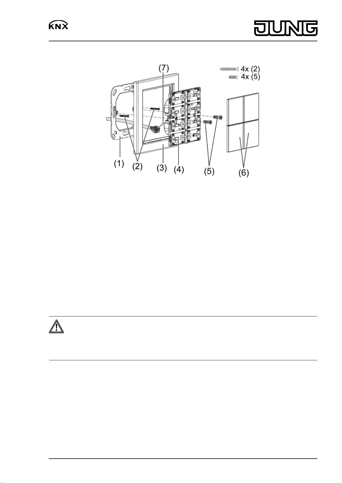
Connecting and mounting the device
picture 1
(1) Supporting ring
(2) Box screws
(3) Design frame
(4) Button sensor module
(5) Plastic screws
(6) Covers
(7) KNX connection terminal
Supporting ring side A for switch design range FD-Design, Supporting ring side B for LS design
range.
Button sensor module 8-fang (picture 2): When mounting on only one flush-mounted socket,
countersink the lower screws into the wall, e.g. with ø 6 x10 mm hole. Use supporting ring as
template.
Button sensor module with illuminable text field: Fasten with only one plastic screw. If possible
label before assembly (see chapter 4.2. Commissioning).
DANGER!
Danger of electrical shock!
When mounting with 230 V socket outlets under a common cover there is a
danger of electrical shocks in the event of a fault!
Use only the supplied plastic screws for fastening to the supporting ring.
o Mount supporting ring (1) in the right orientation on an appliance box. Use only the
supplied box screws (2). Note marking TOP; marking A or B in front.
o Push frame (3) onto supporting ring.
o Connect button sensor module (4) to the KNX using KNX connecting terminal (7) and push
onto the supporting ring.
o Fix push-button module to supporting ring using the supplied plastic screws (5). Tighten the
plastic screws only lightly.
o Before mounting the control surfaces (6), load the physical address into the device (see
chapter 4.2. Commissioning).
32558813
J:0082558813
3/7
19.06.2009
Page 4
Push-button module with integrated BCU Standard / Universal
picture 2
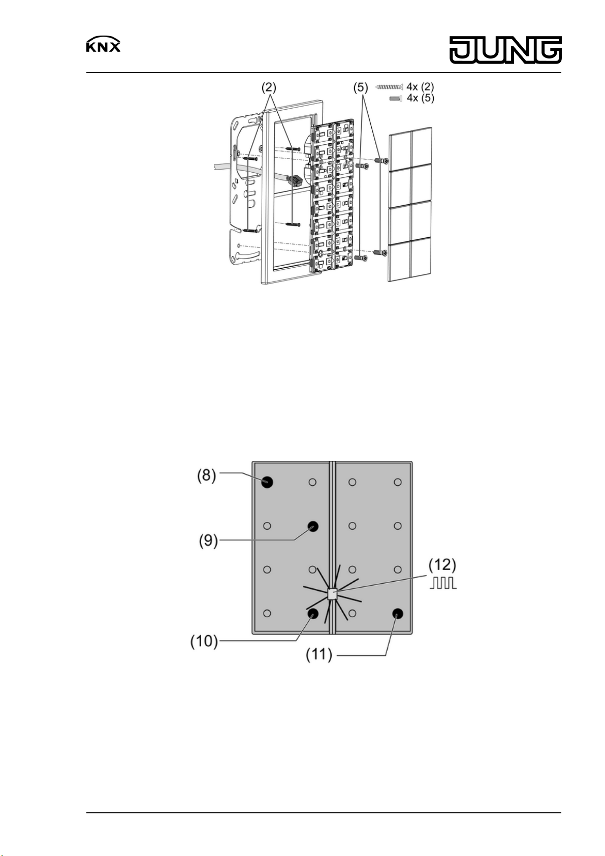
4.2 Commissioning
Loading the physical address and application software
Configuration and commissioning with ETS3.0d Patch A.
The device is connected and ready for operation.
The control surfaces are not mounted yet.
i If the device does not receive any application software, or the wrong application software,
then the blue operation LED flashes slowly.
picture 3: Activating programming mode
o Activate programming mode: Press and hold push-button at the upper left (8). Then press
push-button at the lower right (9, 10 or 11):
32558813
J:0082558813
4/7
19.06.2009
Page 5

Push-button module with integrated BCU Standard / Universal
Push button module Prog. push-button
2-gang with text field, 8-gang, 4-gang, 3-gang (8) + (9)
1-gang with text field, 2-gang (8) + (10)
1-gang (8) + (11)
The operation LED (12) flashes quickly.
o Load physical address into the device.
The operation LED (12) returns to its previous state – off, on, or flashing slowly.
o Write the physical address on the device label.
o Load application software into the device.
Fitting the control surfaces
The button sensor module covers will be necessary as control surfaces (see chapter 5.2.
Accessories).
The physical address is loaded into the device.
Observe the layout of the covers (picture 4).
o Place control surfaces on the device in the right orientation and snap in with a short push.
Note marking on inner side TOP = observe top.
32558813
J:0082558813
picture 4
5/7
19.06.2009
Page 6

Push-button module with integrated BCU Standard / Universal
Assemble control surfaces which can be labelled
picture 5
o Label customarily used foil or other with help of the Jung labelling software and insert into
the buttons (picture 5).
Label illuminable text field
picture 6
The illuminable text fields are only accessible in unassembled condition.
i Do not label the inserted foil, but rather for example customarily used transparent
membranes. The inserted foil ensures even illumination and for this possesses a special
coating.
o Dismantle the button sensor module if necessary. Carry out the installation steps in the
reversed sequence.
o Pull the labelling drawer out sideways (picture 6).
o Insert the labelled foil into the drawer.
o Push drawer back in.
5 Appendix
5.1 Technical data
KNX medium TP 1
Commissioning mode S mode
Rated voltage KNX DC 21 V ... 32 V SELV
Power consumption KNX typical 150 mW
32558813
J:0082558813
6/7
19.06.2009
Page 7
Push-button module with integrated BCU Standard / Universal
Connection mode KNX Connection terminal
Ambient temperature -5 ... +45 °C
Storage/transport temperature -25 ... +70 °C
Safety class III
5.2 Accessories
Cover 1-gang Art.-No.: FD..901 TSA..
Cover 2-gang Art.-No.: FD..902 TSA..
Cover 4-gang Art.-No.: FD..904 TSA..
Cover with symbol, 1-gang Art.-No.: FD ..901 TSAP..
Cover with symbol, 2-gang Art.-No.: FD ..902 TSAP..
Cover with symbol, 4-gang Art.-No.: FD ..904 TSAP..
Cover with inscription field, 1-gang Art.-No.: FD ..901 TSANA..
Cover with inscription field, 2-gang Art.-No.: FD ..902 TSANA..
Cover with inscription field, 4-gang Art.-No.: FD ..904 TSANA..
5.3 Warranty
We reserve the right to make technical and formal changes to the product in the interest of
technical progress.
We provide a warranty as provided for by law.
Please send the unit postage-free with a description of the defect to our central customer
service office:
ALBRECHT JUNG GMBH & CO. KG
Service Center
Kupferstr. 17-19
D-44532 Lünen
Service-Line: +49 (0) 23 55 . 80 65 51
Telefax: +49 (0) 23 55 . 80 61 89
mail.vka@jung.de
General equipment
Service-Line: +49 (0) 23 55 . 80 65 55
Telefax: +49 (0) 23 55 . 80 62 55
mail.vkm@jung.de
KNX equipment
Service-Line: +49 (0) 23 55 . 80 65 56
Telefax: +49 (0) 23 55 . 80 62 55
mail.vkm@jung.de
The Πsymbol is a free trade symbol, which is solely intended for the authorities and does not
guarantee any properties.
ALBRECHT JUNG GMBH & CO. KG
Volmestraße 1
D-58579 Schalksmühle
Telefon: +49.23 55.8 06-0
Telefax: +49.23 55.8 06-1 89
E-mail: mail.info@jung.de
Internet: www.jung.de
www.jung-katalog.de
32558813
J:0082558813
7/7
19.06.2009
 Loading...