

Jung 30XX TSM Series, 3091 TSM, 3071 TSM, 3072 TSM, 3073 TSM Operating Instructions Manual
...Page 1
KNX Touch sensor module with integrated coupler
‘Standard / Universal’
Ref.-no.: 30xx TSM..
Operating Instructions
Touch senor module with integrated
coupler ‘Standard / Universal’
1. Safety warnings
Attention: Electrical equipment must be installed and fitted only by
qualified electricians. Risk of electric shock! Risk of electric shock
in the event of malfunction, if the device is fitted in combination with
230 V socket outlets under one cover. For fastening to the
supporting ring, use only the plastic screws supplied with the
device. Failure to observe any of the installation instructions may
cause damage to the device and result in fire and other hazards.
Risk of damage to the device due to electrostatic discharge. Use
only the plastic screws supplied with the device.
2. Function
System information
This device is a product of the KNX system and complies with KNX
directives. Detailed technical knowledge obtained in KNX training courses
is a prerequisite to proper understanding. The functionality of this device
depends on the software. Detailed information on loadable software and
attainable functionality as well as the software itself can be obtained from
the manufacturer’s product database. Planning, installation and
commissioning of the unit is effected by means of KNX-certified software.
The full functionality with KNX commissioning software from version
ETS3.0d. onwards. The product database, technical descriptions and
conversion programs and other utilities are available in the Internet at
www.jung.de
Stand: Jul-08 325 588 03
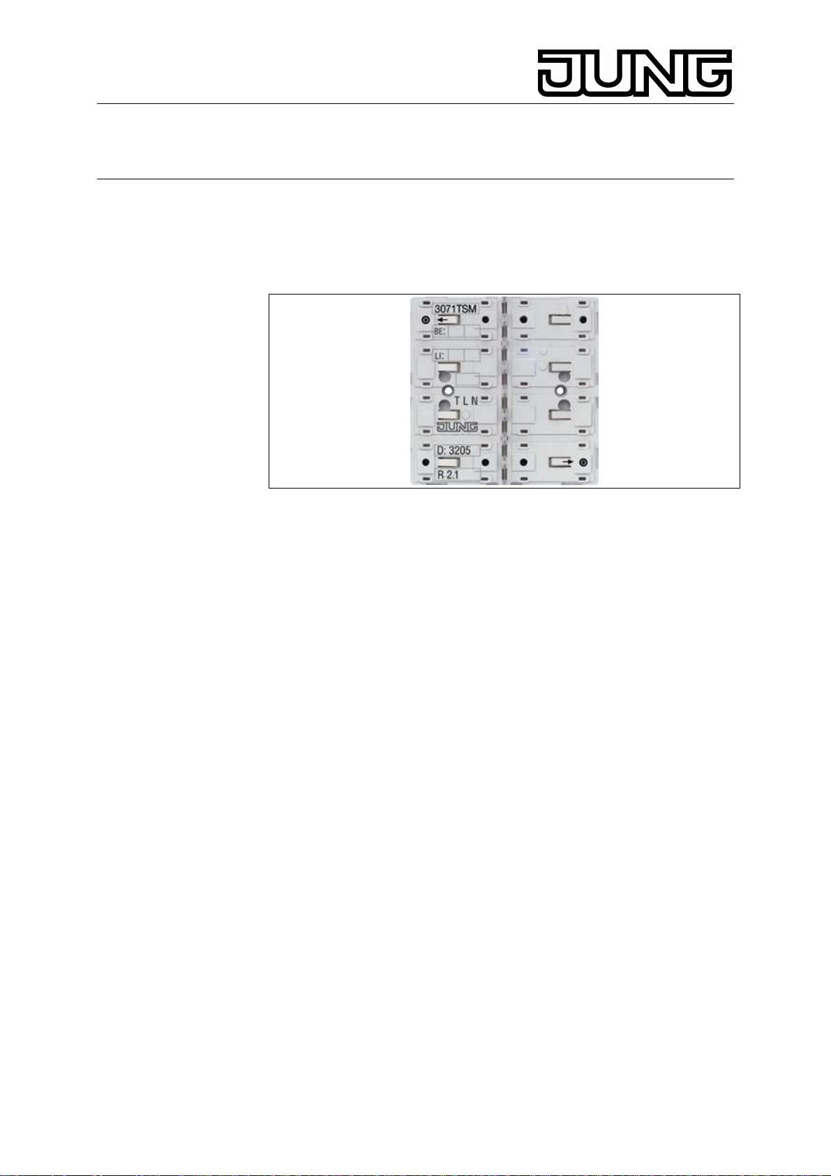
Function
Touch sensor for switching, dimming, shutter operation, value
transmission, recall and storage of lightscenes. Each key rocker is
‚divided‘ into an upper and a lower half (FIG. A) and has a function
assigned to it. Each rocker is equipped with a red status LED.
The blue operation LED can be used as an orientation light besides
indicating the programming state of the touch sensor module.
Page 2
KNX Touch sensor module with integrated coupler
‘Standard / Universal’
Ref.-no.: 30xx TSM....
• Flashing fast: programming the physical address
• Flashing slowly: wrong or no application software
1
1
1 2
1 2
2
3
A
3 4
1
1
Abc
Abc
2
B
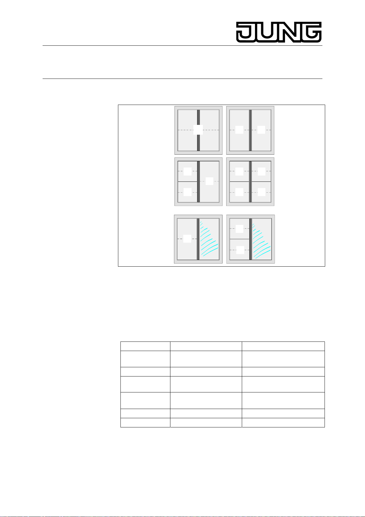
Additional functions with touch sensor module ‚Universal‘: Vertical or
horizontal rocker operation, single-face function, full-face function, two
functions per rocker, two status LEDs per rocker, room temperature
sensing (only 8-key model, art. no.: 3098 TSM). With illuminated
inscription/labelling field as an option (FIG. B).
Key covers
For operation, the device must be equipped with the corresponding touch
sensor module covers (to be ordered separately), e.g.:
1-key 3071 or. 3091 TSM 1 x FD..901 TSA..
w. labelling
field
2-key 3072 or. 3092 TSM 2 x FD..902 TSA..
w. labelling
field
3-key 3073 or. 3093 TSM 1 x FD..902 TSA..
4-key 3074 or. 3094 TSM 4 x FD..904 TSA..
8-key 3078 or. 3098 TSM 4 x FD..908 TSA..
Covers with article nos. FD..90 TSA NA.. can be labelled. Commercialgrade foils can be labelled with the labelling software from JUNG
→www.jung-beschriftungsservice.de.
2
3091 TSML 1 x FD..902 TSA..
3092 TSML 2 x FD..904 TSA..
2 x FD..904 TSA..
Page 3
KNX Touch sensor module with integrated coupler
‘Standard / Universal’
Ref.-no.: 30xx TSM....
3. Fitting instructions
• Touch sensor module for switch programs FD-Design (type A:
height of frame 6 mm) LS-Design (type B: height of frame 11 mm
Inscription on supporting frame: „Type A“ or „Type B“.
• Fasten the 8-key touch sensor module with four plastic screws on
the supporting ring (FIG. D). In case of fitting on a single flush-
mounting box, the screws (4.1) must be sunk in the wall (e.g. hole ø
6 x 10 mm). Use the supporting ring as a template for drilling.
• Touch sensor modules with illuminated inscription field: Fastening
with only one plastic screw. If possible, write the text on the label
before fitting
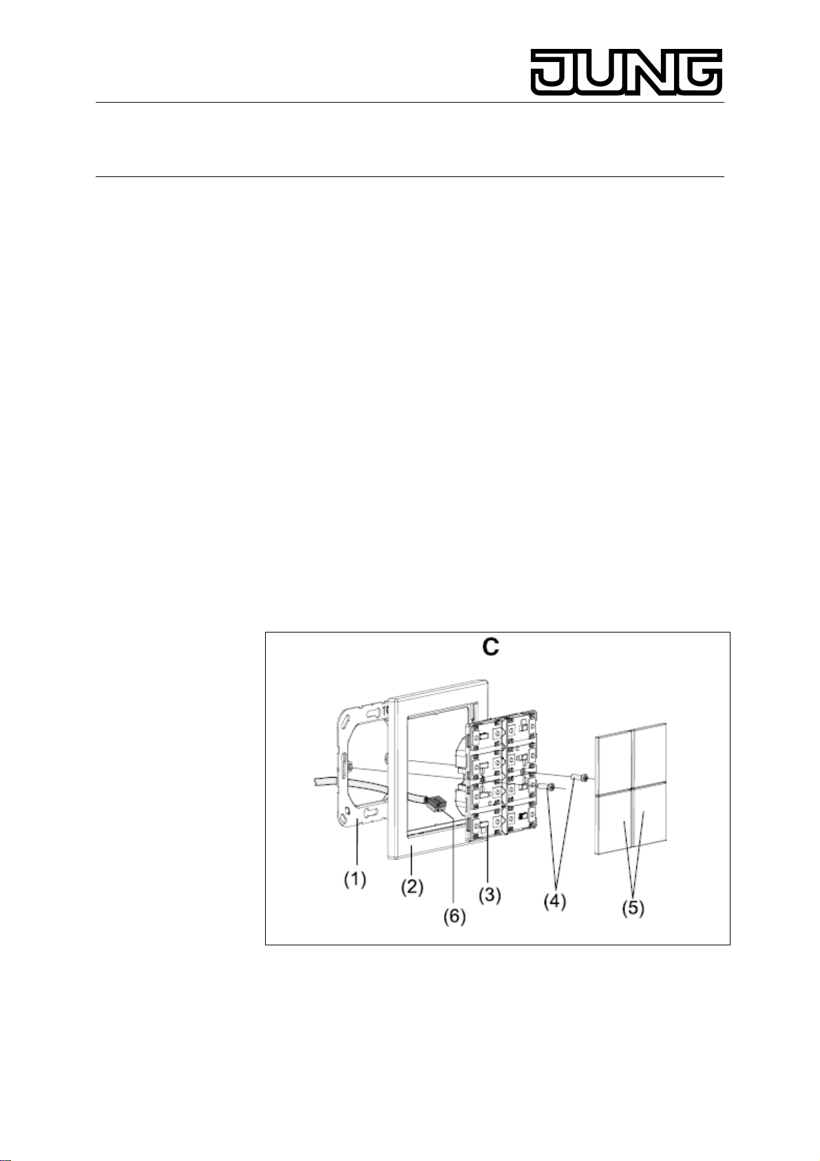
3.1. Montage
1.Fit supporting ring (1) in correct position on a flushmounting box (DIN
49073) (observe the „TOP“ mark, „Type A“ or „Typ B“ in front). Use the
screws supplied with the mounting box.
2. Place decorative frame (2) on the supporting ring.
3. Connect the touch sensor module (3) with the KNX connecting terminal
(6) to the KNX and plug onto supporting ring (lead bus wires out at the
bottom).
4. Fasten touch sensor module with the plastic screws supplied (4) on the
supporting ring (protection against removal or theft). Tighten the plastic
screws without using force.
Before fitting the covers (5) load the physical address into the device..
3
Page 4

KNX Touch sensor module with integrated coupler
‘Standard / Universal’
Ref.-no.: 30xx TSM....
Allocation of physical address (Fig. E)
1. Activate the programming mode: Before fitting the covers press button
(7) and hold depressed. Then press the button at the lower right (8, 9 or
10).
The operation LED flashes fast
2. End the programming mode:
– after storing of the physical address
– by pressing any button
3. Note the physical address on the touch sensor label.
4. Load the application software into the device after the physical address
has been taken over.
4
Page 5

KNX Touch sensor module with integrated coupler
‘Standard / Universal’
Ref.-no.: 30xx TSM....
Fitting of the key covers
Install the covers one by one on the touch sensor module. Position of the
covers see FIG. A / B. When the cover is correctly aligned (observe TOP
mark on the inside), snap it onto the sensor with a brief press.
Inscription labels (Fig. F)
The covers with article nos. FD..90x TSA NA.. can be labelled. For
labelling, commercial-grade foils can be printed with the JUNG inscription
software and inserted into the keys. Fit as shown in FIG. F.
5
Page 6

KNX Touch sensor module with integrated coupler
‘Standard / Universal’
Ref.-no.: 30xx TSM....
Illuminated nameplate (Fig. G)
The illuminated nameplates are accessible only before fitting.
Important: Do not write the name on the foil in the device, but on a
commercial-grade transparent foil instead. The foil in the device is used
for the uniform distribution of the illumination light and has a special
coating for this purpose.
1. If necessary, dismantle the touch sensor module (byreversing the
fitting sequence).
2. Pull out the label drawer.
3. Place labelled foil into the drawer and slide back I place.
4. Technische Daten
Medium : TP1 (KNX)
Commissioning mode: S-Mode (ETS)
Power supply : 21 ... 32 V DC
Connection: KNX connecting terminal
Power consumption: max. 150 mW
Type of protection: IP 20
Safety class: III
Ambient temperature:: -5 °C ... +45 °C
Storage / transport temperature: -25 °C ... +70 °C
6
Page 7

KNX Touch sensor module with integrated coupler
‘Standard / Universal’
Ref.-no.: 30xx TSM....
5. Guarantee
Our products are under guarantee within the scope of the statutory
provisions.
Please return the unit postage paid to our central service
department giving a brief description of the fault:
ALBRECHT JUNG GMBH & CO. KG
Service-Center
Kupferstr. 17-19
D-44532 Lünen
Service-Line: +(49) 23 55 . 80 65 51
Telefax: +(49) 23 55 . 80 61 65
E-Mail: mail.vka@jung.de
General equipment
Service-Line: +(49) 23 55 . 80 65 55
Telefax: +(49) 23 55 . 80 62 55
E-Mail: mail.vkm@jung.de
KNX equipment
Service-Line: +(49) 23 55 . 80 65 56
Telefax: +(49) 23 55 . 80 62 55
E-Mail: mail.vkm@jung.de
The CE-Sign is a free trade sign addressed exclusively to the
authorities and does not include any warranty of any properties.
7
 Loading...