

Page 1
Binary input
Binary input 4-gang, 230 V
Art. No. 2114 REG
Binary input 8-gang, 230 V
Art. No. 2118 REG
Binary input 6-gang, 24 V
Art. No. 2126 REG
Operating instructions
1 Safety instructions
Electrical equipment may only be installed and fitted by electrically skilled persons.
Failure to observe the instructions may cause damage to the device and result in fire and
other hazards.
Danger of electric shock. Do not connect FELV and SELV/PELV systems together. When
connecting SELV/PELV systems, ensure safe isolation from other voltages.
These instructions are an integral part of the product, and must remain with the end
customer.
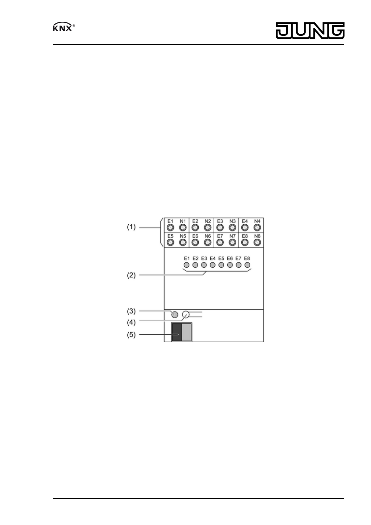
2 Device components
82540413
J:0082540413
Figure 1: Binary input 8gang 230 V
1/7
06.08.2013
Page 2
Binary input
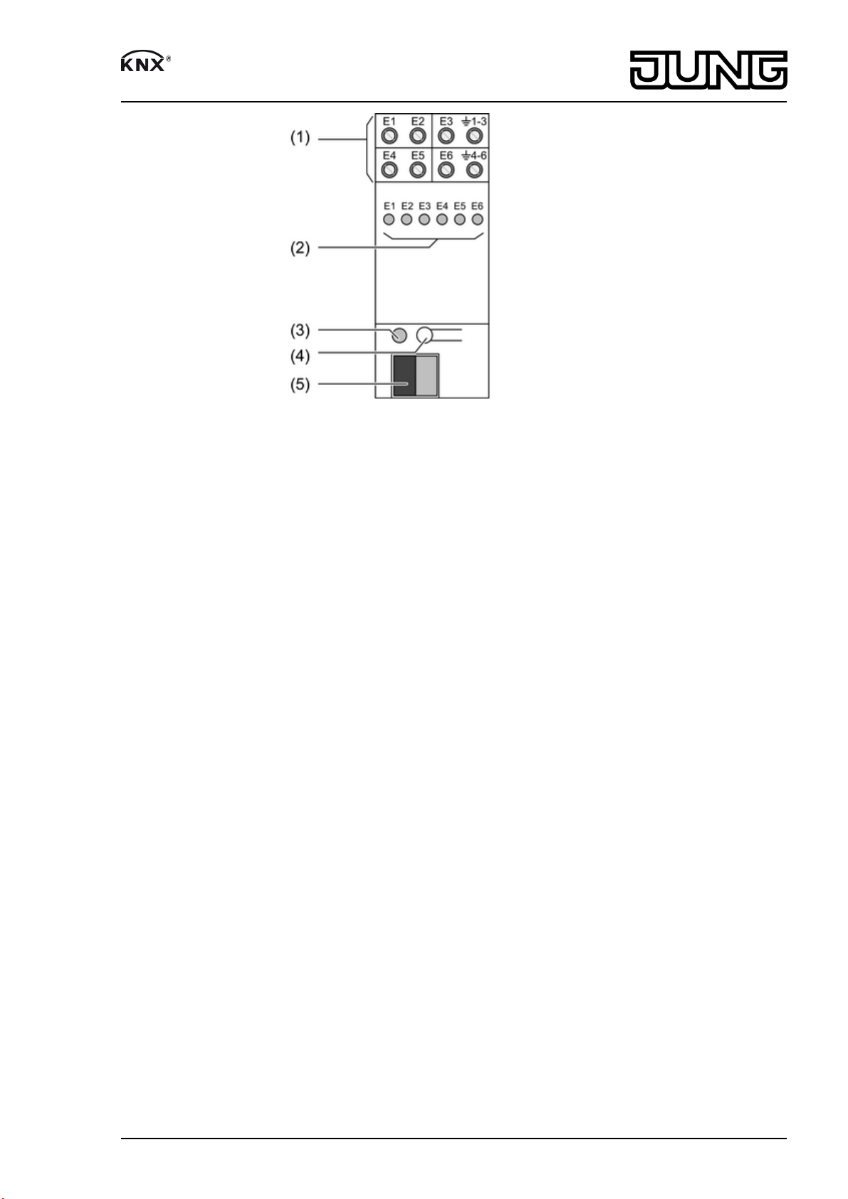
Figure 2: Binary input 6gang 24 V
(1) Connection for inputs
(2) Status LED inputs, red
On: voltage for signal level '1' present.
Off: voltage for signal level '0' present.
(3) Programming LED
(4) Programming button
(5) KNX connection
3 Function
System information
This device is a product of the KNX system and complies with the KNX directives. Detailed
technical knowledge obtained in KNX training courses is a prerequisite to proper
understanding.
The function of this device depends upon the software. Detailed information on loadable
software and attainable functionality as well as the software itself can be obtained from the
manufacturer´s product database. Planning, installation and commissioning of the device are
carried out with the aid of KNX-certified software. The latest versions of product database and
the technical descriptions are available on our website.
Intended use
- Polling of conventional switching or push-button contacts in KNX systems, for reporting of
states, operation of loads, etc.
- Mounting on DIN rail according to EN 60715 in distribution boxes
Product characteristics
- Status LED for each input
- Detection of voltage levels and changes on the input
- Transmitting the input state to the bus
- Transmission behaviour freely settable
- Functions: switching, dimming, blinds up/down, brightness values, temperatures, calling up
and saving light moods
- Inputs 1 and 2: pulse and switch counter function
- Inputs can be disabled separately
Characteristics of 230 V binary inputs
- Different external conductors L1, L2, L3 can be connected
- Separate reference potentials N for each input
82540413
J:0082540413
2/7
06.08.2013
Page 3
Binary input
Characteristics of 24 V binary input
- AC and DC voltages can be connected
- Separate reference potentials for inputs E1...E3 and E4...E6
4 Information for electrically skilled persons
4.1 Fitting and electrical connection
DANGER!
Electrical shock when live parts are touched.
Electrical shocks can be fatal.
Before carrying out work on the device or load, disengage all the
corresponding circuit breakers. Cover up live parts in the working environment.
Fitting the device
Observe the temperature range. Ensure adequate cooling.
o Mount device on DIN rail.
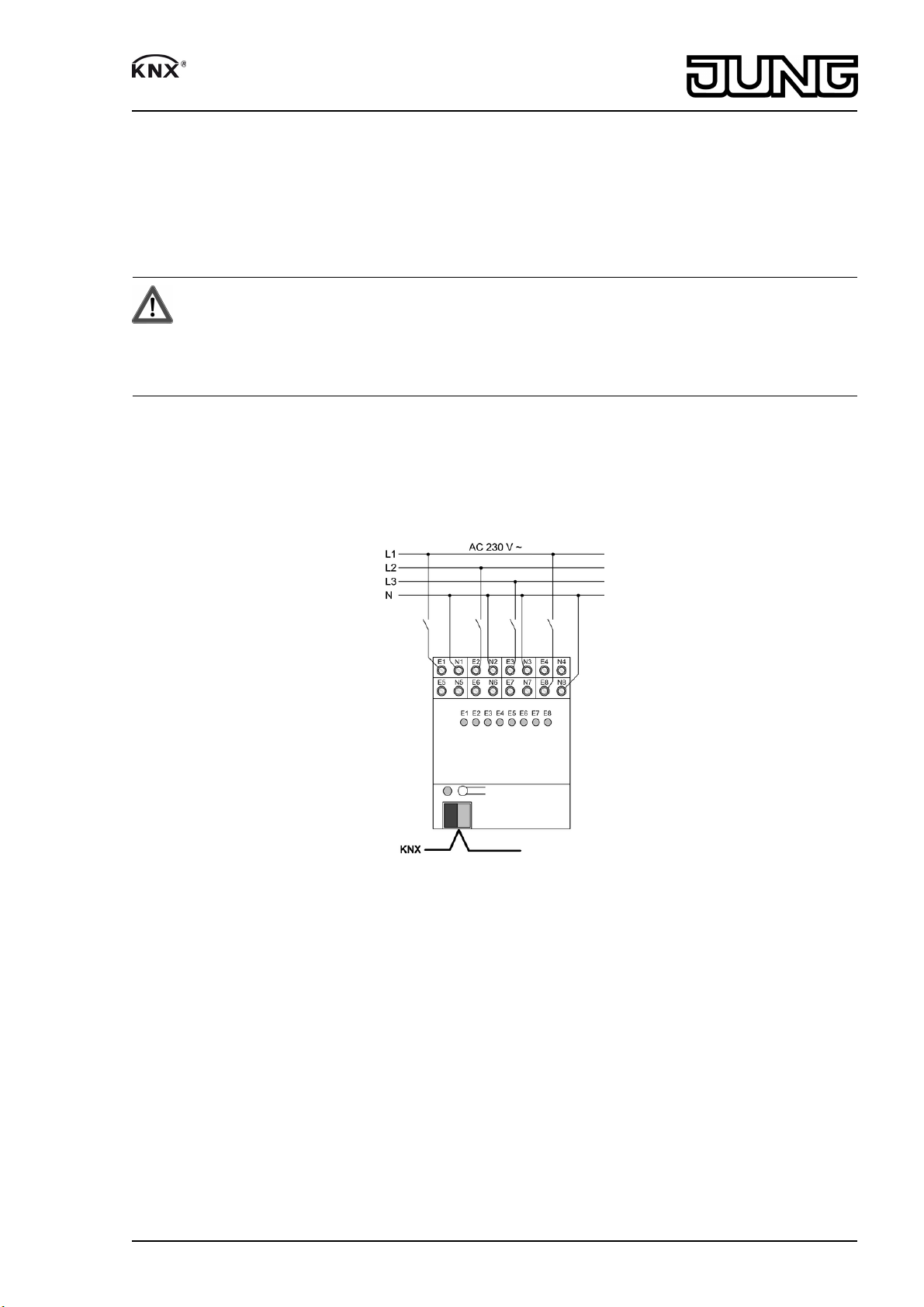
Connect 230 V binary inputs
Figure 3: Connection example for 230 V binary inputs
o Connect device as shown in the connection example (figure 3). Connect reference
potential N separately for each input.
82540413
J:0082540413
3/7
06.08.2013
Page 4

Binary input
Connect 24 V binary input
Figure 4: Connection example for 24 V binary input
For DC operation: observe polarity of the input voltage.
o Connect device as shown in the connection example (figure 4). Common reference
potential for inputs E1...E3 and E4...E6.
Installing the cover
It is necessary to install a cover to protect the bus connection against hazardous voltages in the
connection area.
Figure 5: Installing the cover
o Route the bus line towards the rear.
o Install cover on top of the bus terminal so that it snaps into place (figure 5).
82540413
J:0082540413
4/7
06.08.2013
Page 5

Binary input
Removing the cover
Figure 6: Removing the cover
o Press the cover to the side and pull it off (figure 6).
4.2 Commissioning
Load the address and the application software
o Switch on the bus voltage.
o Assign physical address.
o Load the application software into the device.
o Note the physical address on the device label.
5 Appendix
5.1 Technical data
Binary input 4-gang, 230 V, Art. No. 2114 REG
Mark of approval VDE
KNX
KNX medium TP 1
Commissioning mode S-mode
Rated voltage KNX DC 21 ... 32 V SELV
Power consumption KNX max. 150 mW
Connection type for bus Connection terminal
Ambient temperature -5 ... +45 °C
Storage/transport temperature -25 ... +70 °C
Inputs
Rated voltage AC 110 ... 230 V ~
Signal level "0" signal AC 0 ... 70 V ~
Signal level "1" signal AC 90 ... 253 V ~
Mains frequency 50 / 60 Hz
Input current at nominal voltage approx. 7 mA
Signal duration min. 200 ms
Signal delay
rising edge approx. 2 ms
falling edge approx. 40 ms
Housing
Fitting width 36 mm / 2 modules
Power loss max. 1.7 W
82540413
J:0082540413
5/7
06.08.2013
Page 6

Binary input
Connection
single stranded 0.5 ... 4 mm²
finely stranded without conductor sleeve 0.5 ... 4 mm²
finely stranded with conductor sleeve 0.5 ... 2.5 mm²
Cable length max. 100 m
Binary input 8-gang, 230 V, Art. No. 2118 REG
Mark of approval VDE
KNX
KNX medium TP 1
Commissioning mode S-mode
Rated voltage KNX DC 21 ... 32 V SELV
Power consumption KNX max. 240 mW
Connection type for bus Connection terminal
Ambient temperature -5 ... +45 °C
Storage/transport temperature -25 ... +70 °C
Inputs
Rated voltage AC 110 ... 230 V ~
Signal level "0" signal AC 0 ... 70 V ~
Signal level "1" signal AC 90 ... 253 V ~
Mains frequency 50 / 60 Hz
Input current at nominal voltage approx. 7 mA
Signal duration min. 200 ms
Signal delay
rising edge approx. 2 ms
falling edge approx. 40 ms
Housing
Fitting width 72 mm / 4 modules
Power loss max. 3.4 W
Connection
single stranded 0.5 ... 4 mm²
finely stranded without conductor sleeve 0.5 ... 4 mm²
finely stranded with conductor sleeve 0.5 ... 2.5 mm²
Cable length max. 100 m
Binary input 6-gang, 24 V, Art. No. 2126 REG
KNX
KNX medium TP 1
Commissioning mode S-mode
Rated voltage KNX DC 21 ... 32 V SELV
Power consumption KNX max. 225 mW
Connection type for bus Connection terminal
Ambient temperature -5 ... +45 °C
Storage/transport temperature -25 ... +70 °C
Inputs
Rated voltage AC/DC 24 V
Signal level "0" signal AC/DC -42 ... +1.8 V
Signal level "1" signal AC/DC 8 ... 42 V
Input current at nominal voltage approx. 4 mA
Signal duration min. 200 ms
Signal delay
rising edge approx. 2 ms
falling edge approx. 40 ms
Housing
Fitting width 36 mm / 2 modules
Power loss max. 2 W
Connection
single stranded 0.2 ... 4 mm²
finely stranded without conductor sleeve 0.34 ... 4 mm²
finely stranded with conductor sleeve 0.14 ... 2.5 mm²
82540413
J:0082540413
6/7
06.08.2013
Page 7

Binary input
Cable length max. 100 m
5.2 Accessories
Connection cover Art. No. 2050 K
5.3 Warranty
We reserve the right to make technical and formal changes to the product in the interest of
technical progress.
We provide a warranty as provided for by law.
Please send the device with a description of the defect to our central customer service office.
ALBRECHT JUNG GMBH & CO. KG
Volmestraße 1
58579 Schalksmühle
Telefon: +49.23 55.8 06-0
Telefax: +49.23 55.8 06-2 04
kundencenter@jung.de
www.jung.de
Service Center
Kupferstr. 17-19
44532 Lünen
Germany
82540413
J:0082540413
7/7
06.08.2013
 Loading...