

Page 1
Light Management Tronic switching insert
Ref.-no.:1254TSE
Operating Instructions
Tronic switching insert
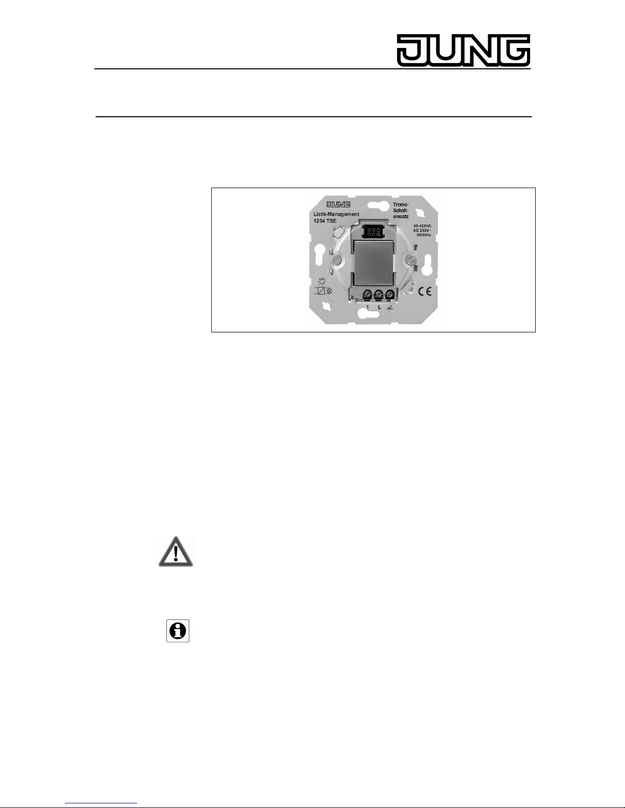
1. Function
The Tronic switching insert is a device provided with an electronic switch
and serving for switching light installations or electrical consumers:
• 230 V incandescent lamps.
• 230 V halogen lamps.
• LV halogen lamps in conjunction with Tronic transformers.
Events are caused by switching commands from the covers such a
automatic switch or presence detector attachment. Switching commands
given through an extension or a radio transmitter lead to well-direct ed
turning on or off. The lamps are turned on by a gentle soft start. This
Operating Instructions leaflet describes the functionality in combination
with the presence detector attachment. For the exact functionalities in
conjunction with the use of other attachments or of the remote control
unit, please refer to the corresponding Operating Instructions leaflets.
2. Safety instructions
Attention: Electrical equipment must be installed and fitted by qualified
electricians only. Not suitable for safety disconnection. Shutting off does
not disconnect the load electrically from the mains. Non-observance of
the installation instructions may cause fire or other hazards.
Do not connect any electronic lamps, e.g. switchable or dimmable
compact fluorescent lamps or LED lamps.
Device can be damaged.
Important
Not suitable for disconnecting. Not suitable for operation in conjunction
with conventional transformers. Do not change the attachment while
mains voltage is applied, as this will entail malfunctioning.
Stand: Feb-10 325 335 13
Page 2
Light Management Tronic switching insert
Ref.-no.:1254TSE
3. Installation Instructions
Install Tronic switching insert (1) in a connection box as per DIN 49073
(Fig. A).
).
Fig. A
The terminals of the Tronic switching insert must be down. Use the Tronic
switching insert only in combination with an attachment. Plug attachment
(2)onto Tronic switching insert (3)together with frame (1). The electrical
contact is established through plug contacts (4). Mains failures of longer
than 1 sec. will lead to turning off the Tronic switching insert.
4. Short-Circuit Protection
Switching off with automatic restarting after short-circuit elimination within
7 sec. For longer short-circuits, permanent switching off until a manual
restart is triggered when a shortstroke key is used.
5. Overtemperature Protection
Switching off in case of excessively high ambient temperature. After
cooling down, the device must be restarted.
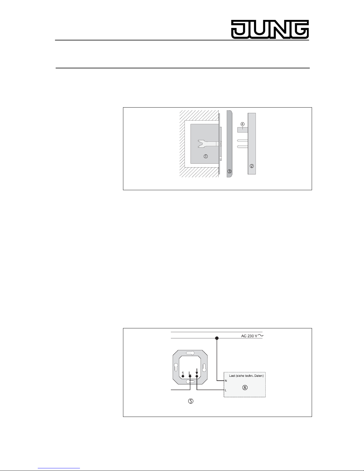
6. Connection
Connect as shown in Fig. B.
Tronic switching insert
g
Load
j
Fig. B
Observe the maximum connected load and the load
details as set out in the Technical Specifications.
2
Page 3

Light Management Tronic switching insert
Ref.-no.:1254TSE
Depending upon the type of installation, the maximum connected load
must be reduced by:
- 6.5 % per 5 °C exceeding of the ambient temperature of 25°C.
- 15% for installation in wooden, gypsum plaster or hollow walls.
- 20% for installation in multiple combinations.
Note the technical connection conditions of the power stations.
7. The Use of Extensions
Connect several extensions as shown in Fig. C.
Fig. C
Connect several extensions as shown in Fig. C.
Control from an extension unit is possible only if the attachment on the
main unit is in place.
Tronic switching insert
g
"2-wire" extension insert
h
Connection of further extensions
i
Load
j
"2-wire" extension insert: Using the short-stroke key leads to
the same functionality as on the
Tronic switching insert.
Mechanical push-button (n. o. contact): ON/OFF (toggling)
Illuminated mechanical pushbuttons must have a separate N terminal.
8. Technical specifications
Nominal voltage: AC 230 V ~, 50 / 60 Hz
Operating temperature: -20 °C ... +45 °C
Connected load: 50 - 420 W/VA
- Incandescent lamps
- HV halogen lamps
- Tronic transformers
Number of Extensions:
"2-wire" extension insert,
mechanical push-button: unlimited
"3-wire" extension insert: 10
Different types of extension units can be combined
Total length of extension connecting cable: max. 100 m
3
Page 4

Light Management Tronic switching insert
Ref.-no.:1254TSE
9. Guarantee
Our products are under guarantee within the scope of the statutory
provisions.
Please return the unit postage paid to our central service
department giving a brief description of the fault:
ALBRECHT JUNG GMBH & CO. KG
Service-Center
Kupferstr. 17-19
D-44532 Lünen
Service-Line: +(49) 23 55 . 80 65 51
Telefax: +(49) 23 55 . 80 61 65
E-Mail: mail.vka@jung.de
General equipment
Service-Line: +(49) 23 55 . 80 65 55
Telefax: +(49) 23 55 . 80 62 55
E-Mail: mail.vkm@jung.de
KNX equipment
Service-Line: +(49) 23 55 . 80 65 56
Telefax: +(49) 23 55 . 80 62 55
E-Mail: mail.vkm@jung.de
The
-Sign is a free trade sign addressed exclusively to the
authorities and does not include any warranty of any properties.
4
 Loading...