

Page 1
Radio Management Radio-repeater plug
Ref.-no.: 100 FR SG
Operating Instructions
Radio-repeater plug
1. Function
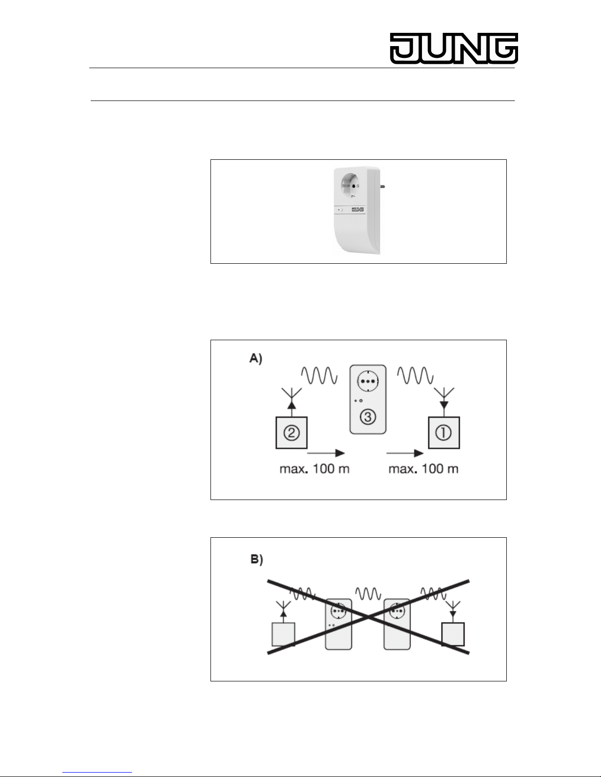
The use of a repeater extends the radius of action of the Radio
Management System by approx. 100 m (free field). Repeater (1) receives
radio telegrams from a radio transmitter (2) and repeats them. The
telegrams are received and evaluated by a radio receiver (3) (Fig. A).
It is not possible to connect repeaters in cascade, i. e. telegrams sent by a
repeater will not be repeated by another repeater (Fig. B).
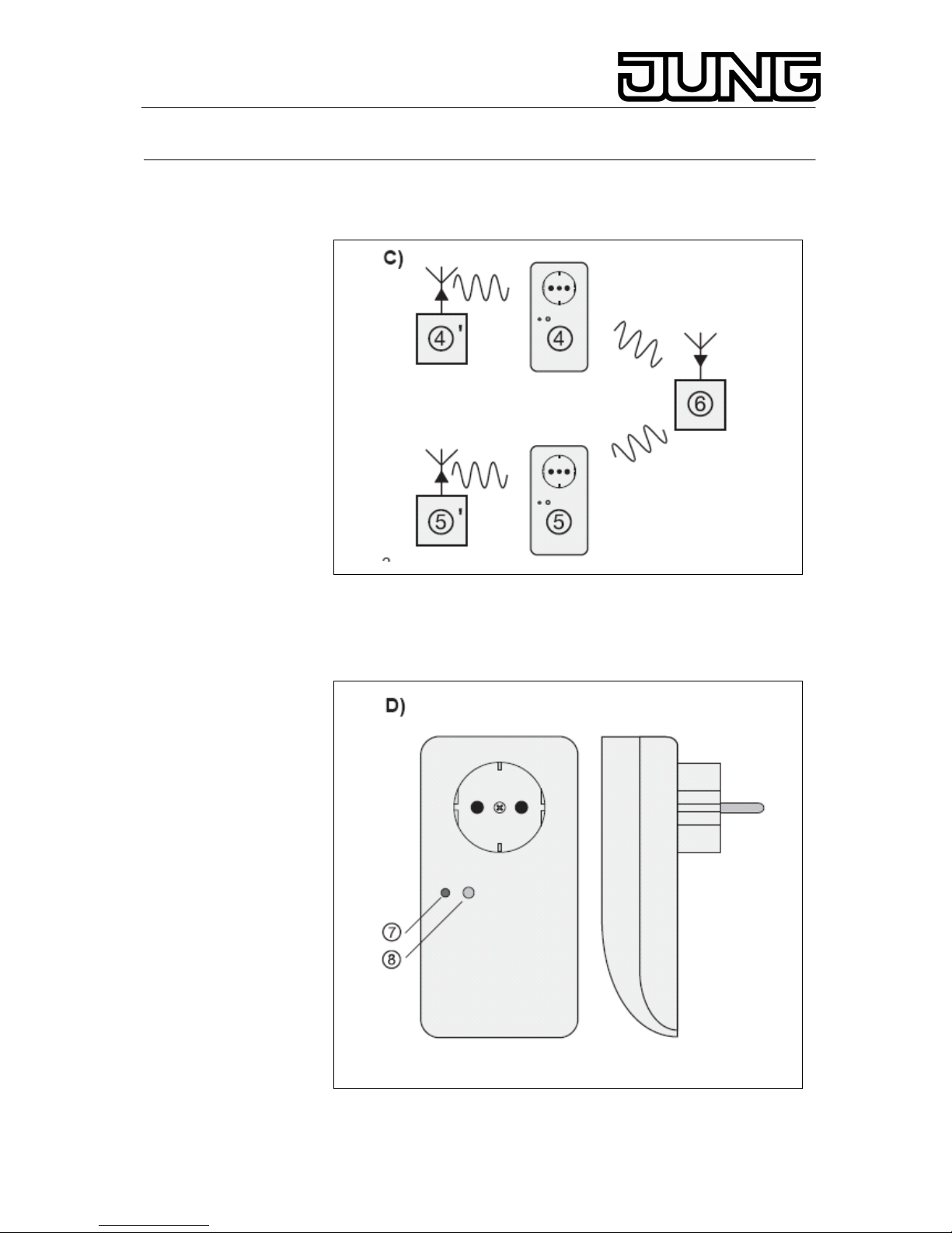
You can install several repeaters within a system, e. g. two repeaters ((4) +
(5)) transmit to one radio actuator (6) (Fig. C).
Stand: Mai-07 325 497 03
Page 2
Radio Management Radio-repeater plug
Ref.-no.: 100 FR SG
Up to 60 radio transmitters can be programmed into one repeater.
.
The repeater has (Fig. D):
(7) a two-colour LED (red, green).
(8) a programming key.
2
Page 3

Radio Management Radio-repeater plug
Ref.-no.: 100 FR SG
LED status indicator
• The operational status is indicated by a two-colour (red, green)
LED.
• Brief lighting up of the red LED indicates reception of a radio
telegram.
• Brief lighting up of the green and the red LED indicates that an
identified radio telegram is being retransmitted.
• Permanent flashing of the red LED for 1 min. indicates readiness
for programming (programming or deleting transmitters).
• If such flashing changes into permanent lighting of the red LED, a
transmitter has been programmed. If it begins to flash faster, a
transmitter has been erased. Refer to the „Programming a Radio
Transmitter into the Repeater“ chapter.
Fuse
The plug of the repeater is provided with a fuse (Fig. E (9)) which will trip in
the event of overload.
If the fuse has tripped, the repeater will also be out of operation. If the
device is defective check this fuse (T 6.3 H 250 V) first. The fuse holder
contains a spare fuse.
Always use fuses of the same rating.
2. Installation
The repeater should be plugged into a wall socket in the middle of the
desired radio link, not in the vicinity of the floor, if possible. The function of
the wall socket is unaffected, i. e. you can plug a load into the socket outlet
of the repeater. This socket is protected by a T 6.3 H 250 V fuse. If this
fuse has tripped, the repeater will also be out of operation.
Installation instructions
• The distance to electrical loads (e. g. microwave oven, hifi and TV
systems) must be at least 0.5 m.
• To avoid saturation of the repeater, the distance between the
repeater and a transmitter must be at least 1 m.
3
Page 4

Radio Management Radio-repeater plug
Ref.-no.: 100 FR SG
3. Programming of radio-control transmitters
To enable the radio repeater to retransmit the radio telegram of a
transmitter, this device must been programmed into the repeater
beforehand. In the programming mode of a radio transmitter, the sensitivity
of the repeater is reduced to approx. 5 m. Therefore, the distance between
the repeater and the radio transmitter to be programmed should be
between 0.5 m and 5 m. For this programming process, the repeater must
be plugged into a wall socket.
Procedure
1. Press the programming key for about 4 s to get into the
programming mode. LED (2) will be flashing for about 1 min. (Fig.
F). The repeater is now in the programming mode.
2. Start the selected radio transmitter and send a radio telegram (Fig.
G); refer to the „Radio Transmitter“ operating instructions): The
entire functionality of a radio transmitter (e. g. channel, ALL-ON,
ALL-OFF and light-scene keys) is programmed after any one of
the transmitter keys has been programmed.
Programming a channel key
Press the channel key for more than 1 s.
Programming a light-scene key
Press the light-scene key for more than 3 s.
4
Page 5

Radio Management Radio-repeater plug
Ref.-no.: 100 FR SG
Programming a detector
Remove the battery from the detector for approx. 2 min. Wait about 1 min.
after re-inserting the battery and make a movement in the detection field of
the detector within the next 10 min.
Programming a presence detector or light sensor
Remove the battery (batteries) from the transmitter for approx. 2 min. After
re-insering the battery (batteries), the transmitter will send programming
telegrams for approx. 30 s.
3. The repeater will confirm storage with the LED lighting up
permanently (Fig. H).
4. The programming mode ends automatically after about 1 min. or it
can be terminated by a short press on the programming key. The
repeater will then be in the operating mode.
Important
• When all of the 60 memory locations are occupied one of the radio
transmitters already stored must be deleted if another one is to be
programmed.
• When a radio channel is programmed (e. g. hand transmitter
‘Komfort’) all channels as well as the ALL-ON, ALL-OFF and the
light-scene keys will automatically be programmed at the same
time.
Deleting a radio transmitter
A radio transmitter already stored can be deleted by reprogramming the
same transmitter (see above). Successful deletion is indicated by the LED
flashing faster (Fig. I).
5
Page 6

Radio Management Radio-repeater plug
Ref.-no.: 100 FR SG
4. Radio transmission
Radio transmission takes place on a non-exclusive path. Therefore,
interference cannot be excluded. This type of radio trans-mission is
not suitable for safety applications such as emergency stops or
emergency calls.
The range of a radio-control system depends on transmitterpower, receiver
characteristics, air humidity, fitting height and building conditions. The
figure illustrates the penetration of building materials by radio waves:
Radio operation
The inter-connection of this radio system with other communication
networks must comply with national legislation.
This radio system must not be used for communication beyond property
boundaries.
For operation within Germany, observe the instructions of the General
Approval published in Amtsblatt. Vfg 73/2000.
6
Page 7

Radio Management Radio-repeater plug
Ref.-no.: 100 FR SG
If utilized in conformity with its designated use, this unit fulfills the
requirements of the R&TTE Directive (1999/5/EG). The complete
declaration of conformitycan be found in the internet under:
www.jung.de/ce
The radio repeater may be operated in all EU and EFTA countries.
5. Technical data
Nominal voltage : AC 230 V~, 50/60 Hz
Fuse : T 6,3 H 250 V
Receive frequency : 433,42 MHz
Modulation : ASK
Transmission range : 100 m typ. (in free field)
Programmable transmitters : 60
Type of protection : IP 20
Temperature range : appr. -20 ... +55 °C
Dimensions (L x W x D) : 136 x 70 x 72 mm
Technical specifications subject to change.
6. Guarantee
Our products are under guarantee within the scope of the statutory
provisions.
Please return the unit postage paid to our central service department
giving a brief description of the fault:
ALBRECHT JUNG GMBH & CO. KG
Service-Center
Kupferstr. 17-19
D-44532 Lünen
Service-Line: +(49) 23 55 . 80 65 51
Telefax: +(49) 23 55 . 80 61 65
E-Mail: mail.vka@jung.de
General equipment
Service-Line: +(49) 23 55 . 80 65 55
Telefax: +(49) 23 55 . 80 62 55
E-Mail: mail.vkm@jung.de
KNX equipment
Service-Line: +(49) 23 55 . 80 65 56
Telefax: +(49) 23 55 . 80 62 55
E-Mail: mail.vkm@jung.de
The
-Sign is a free trade sign addressed exclusively to the
authorities and does not include any warranty of any properties.
7
 Loading...