

Page 1
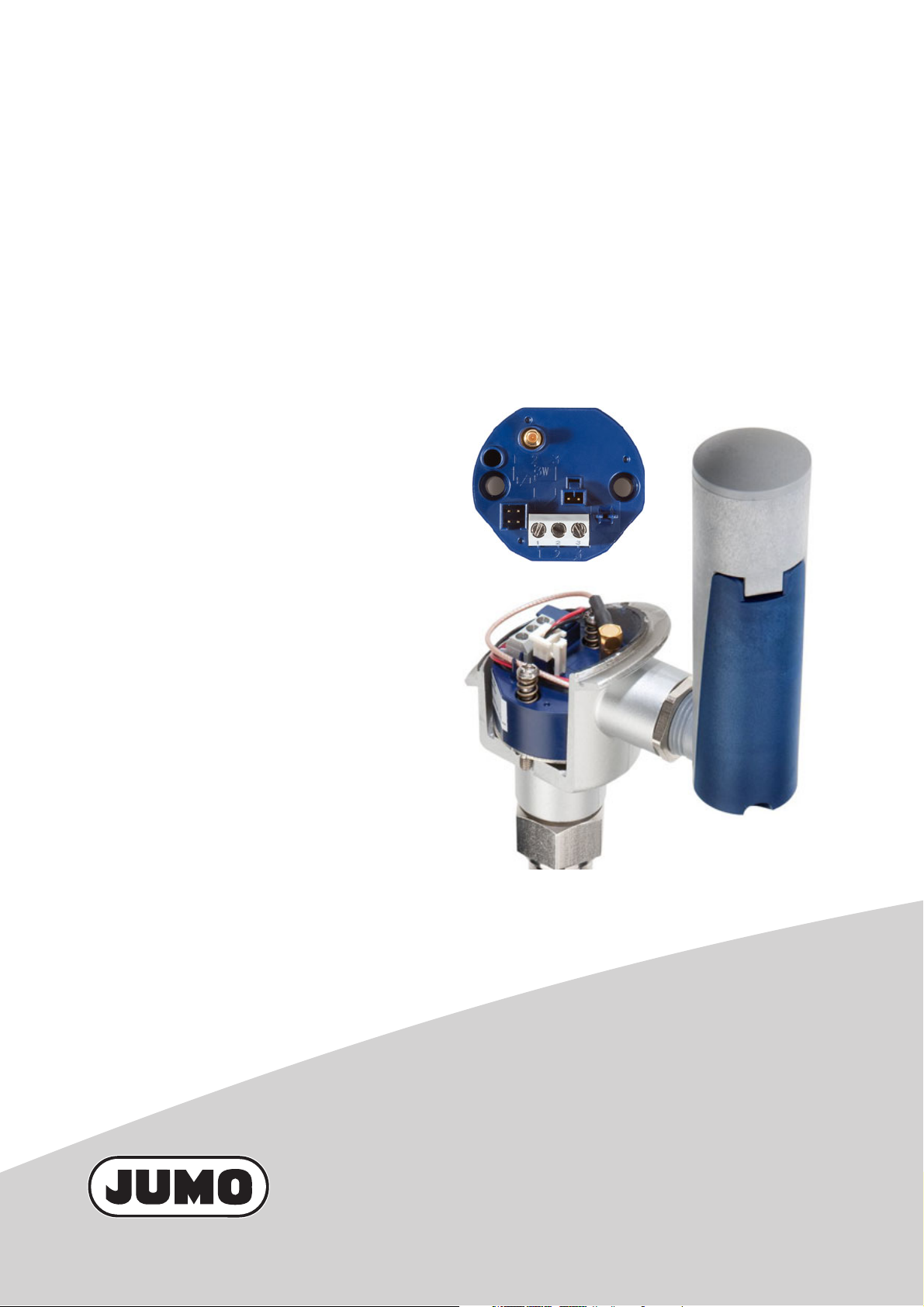
JUMO Wtrans B
Programmable head transmitter
with radio transmission
B 70.7060.0
Operating Manual
2010-08-11/00536757
Page 2

Page 3

Contents
1 Introduction . . . . . . . . . . . . . . . . . . . . . . . . . . . . . . . . . . . . . . . . . . . . . . . . . . . . . .5
1.1 Safety information . . . . . . . . . . . . . . . . . . . . . . . . . . . . . . . . . . . . . . . . . . . . . . . . . . . . . . . . . . . . . 5
1.2 Description . . . . . . . . . . . . . . . . . . . . . . . . . . . . . . . . . . . . . . . . . . . . . . . . . . . . . . . . . . . . . . . . . . 6
1.3 Block diagram . . . . . . . . . . . . . . . . . . . . . . . . . . . . . . . . . . . . . . . . . . . . . . . . . . . . . . . . . . . . . . . . 6
1.4 Dimensions . . . . . . . . . . . . . . . . . . . . . . . . . . . . . . . . . . . . . . . . . . . . . . . . . . . . . . . . . . . . . . . . . . 7
1.4.1 Transmitter . . . . . . . . . . . . . . . . . . . . . . . . . . . . . . . . . . . . . . . . . . . . . . . . . . . . . . . . . . . . . . . . . . 7
1.4.2 Antenna-battery case . . . . . . . . . . . . . . . . . . . . . . . . . . . . . . . . . . . . . . . . . . . . . . . . . . . . . . . . . . 7
1.5 Connection elements and connectors . . . . . . . . . . . . . . . . . . . . . . . . . . . . . . . . . . . . . . . . . . . . . . 8
2 Identifying the instrument version . . . . . . . . . . . . . . . . . . . . . . . . . . . . . . . . . . .9
2.1 Rating plate . . . . . . . . . . . . . . . . . . . . . . . . . . . . . . . . . . . . . . . . . . . . . . . . . . . . . . . . . . . . . . . . . . 9
2.2 Order details . . . . . . . . . . . . . . . . . . . . . . . . . . . . . . . . . . . . . . . . . . . . . . . . . . . . . . . . . . . . . . . . 10
2.3 Scope of delivery . . . . . . . . . . . . . . . . . . . . . . . . . . . . . . . . . . . . . . . . . . . . . . . . . . . . . . . . . . . . . 10
2.4 Accessories . . . . . . . . . . . . . . . . . . . . . . . . . . . . . . . . . . . . . . . . . . . . . . . . . . . . . . . . . . . . . . . . . 10
3 Probe preparation . . . . . . . . . . . . . . . . . . . . . . . . . . . . . . . . . . . . . . . . . . . . . . . .11
3.1 Fitting/exchanging the battery . . . . . . . . . . . . . . . . . . . . . . . . . . . . . . . . . . . . . . . . . . . . . . . . . . . 11
3.2 Safety information concerning lithium batteries . . . . . . . . . . . . . . . . . . . . . . . . . . . . . . . . . . . . . . 13
3.3 Battery service life . . . . . . . . . . . . . . . . . . . . . . . . . . . . . . . . . . . . . . . . . . . . . . . . . . . . . . . . . . . . 13
3.4 Disposal of lithium batteries . . . . . . . . . . . . . . . . . . . . . . . . . . . . . . . . . . . . . . . . . . . . . . . . . . . . 13
4 Probe range . . . . . . . . . . . . . . . . . . . . . . . . . . . . . . . . . . . . . . . . . . . . . . . . . . . . .15
4.1 General information about radio transmission . . . . . . . . . . . . . . . . . . . . . . . . . . . . . . . . . . . . . . . 15
4.2 Possible impairment of radio transmission . . . . . . . . . . . . . . . . . . . . . . . . . . . . . . . . . . . . . . . . . 16
5 Installation . . . . . . . . . . . . . . . . . . . . . . . . . . . . . . . . . . . . . . . . . . . . . . . . . . . . . .19
5.1 Information about fastening, securing and arrangement . . . . . . . . . . . . . . . . . . . . . . . . . . . . . . . 19
5.2 Installing the antenna-battery case . . . . . . . . . . . . . . . . . . . . . . . . . . . . . . . . . . . . . . . . . . . . . . . 20
5.3 Installing the transmitter . . . . . . . . . . . . . . . . . . . . . . . . . . . . . . . . . . . . . . . . . . . . . . . . . . . . . . . 21
5.4 Aligning the antenna . . . . . . . . . . . . . . . . . . . . . . . . . . . . . . . . . . . . . . . . . . . . . . . . . . . . . . . . . . 22
6 Electrical connection . . . . . . . . . . . . . . . . . . . . . . . . . . . . . . . . . . . . . . . . . . . . .23
6.1 Safety information . . . . . . . . . . . . . . . . . . . . . . . . . . . . . . . . . . . . . . . . . . . . . . . . . . . . . . . . . . . . 23
6.2 Connection elements and connectors . . . . . . . . . . . . . . . . . . . . . . . . . . . . . . . . . . . . . . . . . . . . . 24
6.3 Connection diagram . . . . . . . . . . . . . . . . . . . . . . . . . . . . . . . . . . . . . . . . . . . . . . . . . . . . . . . . . . 25
6.3.1 Voltage supply . . . . . . . . . . . . . . . . . . . . . . . . . . . . . . . . . . . . . . . . . . . . . . . . . . . . . . . . . . . . . . . 25
6.3.2 Analog inputs . . . . . . . . . . . . . . . . . . . . . . . . . . . . . . . . . . . . . . . . . . . . . . . . . . . . . . . . . . . . . . . . 25
6.3.3 Output . . . . . . . . . . . . . . . . . . . . . . . . . . . . . . . . . . . . . . . . . . . . . . . . . . . . . . . . . . . . . . . . . . . . . 26
6.3.4 Interface . . . . . . . . . . . . . . . . . . . . . . . . . . . . . . . . . . . . . . . . . . . . . . . . . . . . . . . . . . . . . . . . . . . 26
7 Setup program . . . . . . . . . . . . . . . . . . . . . . . . . . . . . . . . . . . . . . . . . . . . . . . . . . .27
3
Page 4

Contents
7.1 General information about the setup program . . . . . . . . . . . . . . . . . . . . . . . . . . . . . . . . . . . . . . . 27
7.2 Hardware and software prerequisites . . . . . . . . . . . . . . . . . . . . . . . . . . . . . . . . . . . . . . . . . . . . . 28
7.3 Establishing the connection between PC and probe . . . . . . . . . . . . . . . . . . . . . . . . . . . . . . . . . . 29
7.4 Probe configuration . . . . . . . . . . . . . . . . . . . . . . . . . . . . . . . . . . . . . . . . . . . . . . . . . . . . . . . . . . . 32
7.4.1 Establishing the communication . . . . . . . . . . . . . . . . . . . . . . . . . . . . . . . . . . . . . . . . . . . . . . . . . 32
7.4.2 Reading the current probe parameters . . . . . . . . . . . . . . . . . . . . . . . . . . . . . . . . . . . . . . . . . . . . 33
7.4.3 Editing probe parameters . . . . . . . . . . . . . . . . . . . . . . . . . . . . . . . . . . . . . . . . . . . . . . . . . . . . . . 33
7.4.4 Transmitting new parameters to the probe . . . . . . . . . . . . . . . . . . . . . . . . . . . . . . . . . . . . . . . . . 34
7.5 ParametersOverview . . . . . . . . . . . . . . . . . . . . . . . . . . . . . . . . . . . . . . . . . . . . . . . . . . . . . . . . . . 35
8 Supplement . . . . . . . . . . . . . . . . . . . . . . . . . . . . . . . . . . . . . . . . . . . . . . . . . . . . .37
8.1 Technical data . . . . . . . . . . . . . . . . . . . . . . . . . . . . . . . . . . . . . . . . . . . . . . . . . . . . . . . . . . . . . . . 37
8.1.1 Analog inputs . . . . . . . . . . . . . . . . . . . . . . . . . . . . . . . . . . . . . . . . . . . . . . . . . . . . . . . . . . . . . . . . 37
8.1.2 Output (radio transmission) . . . . . . . . . . . . . . . . . . . . . . . . . . . . . . . . . . . . . . . . . . . . . . . . . . . . . 39
8.1.3 Electrical data . . . . . . . . . . . . . . . . . . . . . . . . . . . . . . . . . . . . . . . . . . . . . . . . . . . . . . . . . . . . . . . 39
8.1.4 Environmental influences . . . . . . . . . . . . . . . . . . . . . . . . . . . . . . . . . . . . . . . . . . . . . . . . . . . . . . 40
8.1.5 Case . . . . . . . . . . . . . . . . . . . . . . . . . . . . . . . . . . . . . . . . . . . . . . . . . . . . . . . . . . . . . . . . . . . . . . 40
4
Page 5
1.1 Safety information
General information
This manual contains information that must be observed in the interest of your own safety and
to avoid damage to assets. This information is supported by symbols which are used in this
manual as follows.
Please read this manual before commissioning the device. Keep the manual in a place accessible to all users at all times.
If difficulties occur during commissioning, please refrain from carrying out any manipulations
that could jeopardize your warranty rights.
Warning signs
CAUTION!
This symbol in combination with the signal word indicates that damage to assets or data
loss will occur if suitable precautions are not taken.
Note signs
1 Introduction
TIP!
This symbol refers to important information about the product or its handling or additional
use.
REFERENCE!
This symbol refers to Further information in other sections, chapters or manuals.
5
Page 6
1 Introduction
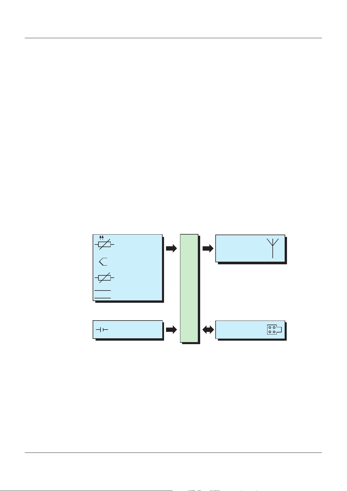
Transmission unit
Transmission
frequency
868.4 MHz
Wtrans B
Power supply
Lithium battery
3.6 V, 2.2 Ah
Interface
Setup
Analog input
RTD
temperature probe
Thermocouple
Potentiometer
Voltage
+
-
1.2 Description
The head transmitter, type "Wtrans B", designed for industrial applications consists of the
transmitter with integrated transmission unit and an antenna-battery case. The transmitter is
designed for integration into the connection heads, form B. Integration into customer-specific
connection heads is also possible. The antenna-battery case is installed on the connection
head via a thread (M20x1.5).
The measured value is transmitted wireless to the receiver of the Wtrans system, displayed on
the LCD display and provided on the receiver via the RS485 interface as well as an analog output. The radio frequency within the ISM band (Industrial, Scientific and Medical Band) is 868.4
MHz. This frequency is almost insensitive to external interferences and allows transmission
even in a rough industrial environment. When using the antenna wall holder with the 3 meter
long cable for the receiver, the maximum open air range is 300 m.
A lithium battery 3.6 V, 2.2 Ah (size AA) is used for the transmitter power supply.
Transmitter (probe) and receiver can be configured with the optional setup program (probe ID,
transmission interval, measuring range and, if necessary, probe type). The configuration data
can be archived on data carriers and printed. Changed parameters can be overwritten again
with the factory settings at any time. The connection between transmitter and PC is established via a PC interface (USB/TTL or TTL/RS232 converter).
1.3 Block diagram
6
Page 7
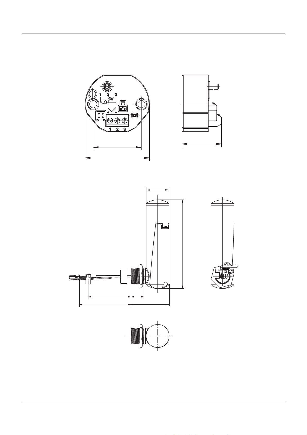
1.4 Dimensions
27
33
Ø44
Ø30
115
17
49.5
approx. 105
approx. 125
1.4.1 Transmitter
1.4.2 Antenna-battery case
1 Introduction
7
Page 8
1 Introduction
(1)
(6)
(6)
(2)
(5)
(4)
(7) (8)
(3)
(9)
(10)
(11)
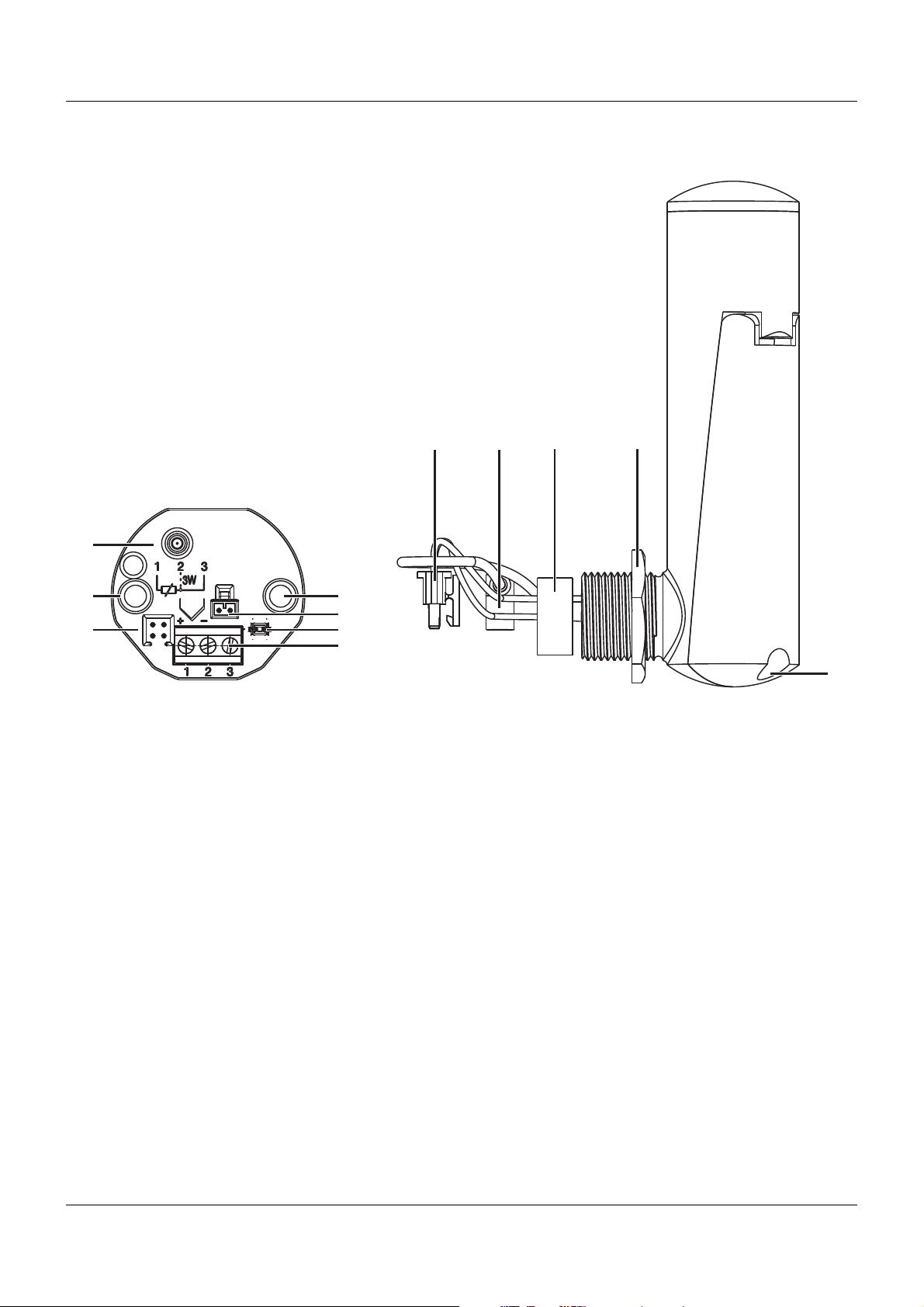
1.5 Connection elements and connectors
(1) SMB antenna connector (antenna connection) (7) Voltage supply socket (battery connection)
(2) Voltage supply connector (battery connection) (8) SMB antenna socket (antenna connection)
(3) Cable guide for antenna cable and voltage supply (9) Seal
(4) Probe connection (10) Locknut
(5) Setup connector (11) Battery lid screw
(6) Fastening holes for installation in the connection
head, form B
8
Page 9

2.1 Rating plate
Position
The rating plate is glued laterally to the transmitter.
The factory set probe ID is additionally stated on a sign fitted on top of the transmitter.
Contents
The rating plate contains important information. This includes, among others:
2 Identifying the instrument version
Description Designation on the rating
Device type Type 707060/8-10/000
Sales No. VARTN 70/XXXXXXXX
Serial No. F-No 0070033801210220006
Voltage supply DC 3.6 V
Probe ID 123
Transmission frequency 868.4 MHz
Device type
Compare the specifications on the rating plate to your order documents. The supplied device
version can be identified using the type key in Chapter 2.2 "Order details", page 10.
Sales No. (VARTN)
The Sales No. provides an unambiguous definition of an article from the catalog. It is important for communication between the sales department and the customer.
Serial No. (F-No.)
The serial number (F-No.) indicates, among others, the production date (year/week) and the
hardware version number.
Example
plate
Production date
Example: F-No. = 0070033801210220006
The figures concerned are in positions 12, 13, 14, 15 (from the left).
Thus the device was produced in the 22nd calendar week in 2010.
Probe ID
The probe ID is factory set. It must be entered and activated on the receiver to establish communication between the probe and receiver. The probe ID can be changed to customer specific requirements using the setup program. The user must exclude that several probes with
identical probe IDs are active.
Transmission frequency
The transmission frequency identifies the frequency and frequency band used by the device
for transmission. In the 868 MHz ISM band (Europe), the transmission is carried out at 868.4
MHz.
9
Page 10

2 Identifying the instrument version
2.2 Order details
(1) Basic type
707060
8 Standard, with factory settings
9 Customized programming according to specification
10 Transmission frequency 868.4 MHz (Europe)
000 none
a
The connection head, form B, is not included in the delivery scope.
b
Please specify the probe ID, transmission interval, measuring range and the probe type in plain text.
Order code /-/
Order example 707060 / 8 - 10 / 000
JUMO Wtrans B
Programmable head transmitter with radio transmission
(2) Input
(3) Output (probe)
(4) Extra codes
(1) (2) (3) (4)
a
b
2.3 Scope of delivery
1 transmitter in the version ordered, without connection head, form B, including fastening material
(2 screws and 2 pressure springs)
1 antenna-battery case with reverse battery protection plug-in connectors
1 lithium battery 3.6 V, 2.2 Ah (size AA), operational, inserted in the antenna-battery case
1 Operating manual B70.7060.0
2.4 Accessories
Article Sales
Lithium battery 3.6 V, 2.2 Ah (size AA) 70/00547559
PC interface with USB/TTL converter, adapter (socket connector) and adapter (pins) 70/00456352
PC interface with TTL/RS232 converter and adapter (socket connector) 70/00350260
Setup program on CD-ROM, multilingual 70/00488887
Setup program including OnlineChart on CD-ROM, multilingual 70/00549067
OnlineChart activation 70/00549188
article No.
10
Page 11
3.1 Fitting/exchanging the battery
CAUTION!
Ensure that soiling, moisture and vapors cannot enter the device.
The device could be destroyed.
When inserting/changing the lithium battery, ensure that the device is not exposed to soiling,
moisture and vapors.
CAUTION!
The probe does not function, if the poles are incorrectly connected.
The battery and the probe electronics could be damaged.
Ensure that the poles are correctly connected.
CAUTION!
Incorrect batteries put safety at risk.
The device could be destroyed when using incorrect batteries.
Only use the lithium battery available as accessories.
Power supply of the probe is provided by the included 3.6 V, 2.2 Ah lithium battery inserted in
the antenna-battery case ready for use.
Battery service life depends on the set transmission interval and the ambient temperature: approx. 1 year with the factory-set values (transmission interval 15 s) and room temperature.
3 Probe preparation
11
Page 12
3 Probe preparation
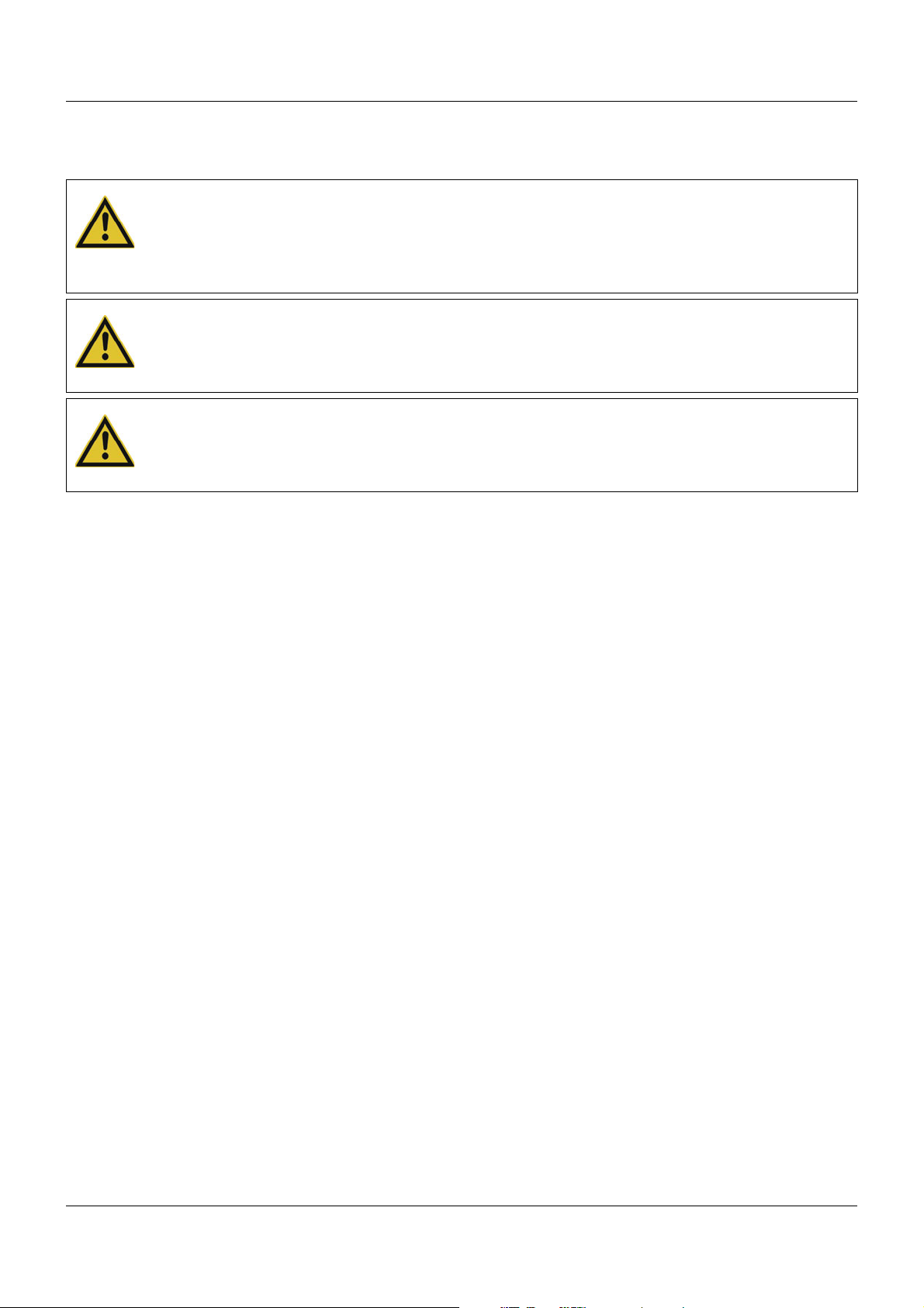
(D)
(A)
(E)
(B)
(C)
If the battery was removed or must be replaced, proceed as follows:
12
Step Activity
1 Undo the battery lid screw (A) on the antenna-battery case and open the case lid (B).
2 Press on the battery in the area of the minus pole (D) to remove the battery (C).
3 When inserting a battery, always insert the minus pole (D) side first followed by the plus
pole (E).
4 Close the case lid (B) again and ensure the correct seal position.
5 Retighten the battery lid screw (A).
Page 13
3 Probe preparation
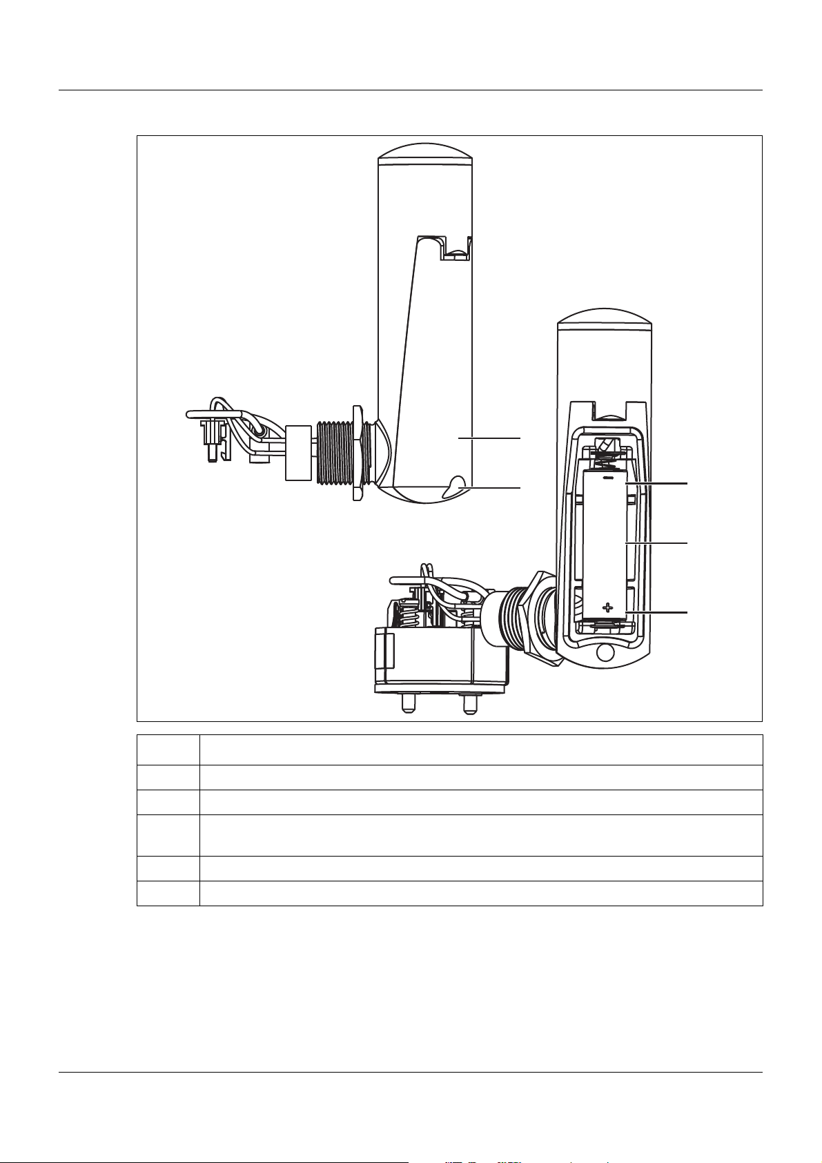
2s
15 s
30 s
90 s
100
80
60
50
40
30
20
10
8
6
5
4
3
2
1
Ambient temperature in °C
-40-30-20-10 0 102030 405060708090
Battery service life in month
3.2 Safety information concerning lithium batteries
Ö http://batterie.jumo.info
3.3 Battery service life
The battery service life, depending on the transmission interval (2 s, 15 s, 30 s, 90 s) and the
ambient temperature, are shown in the following figure.
3.4 Disposal of lithium batteries
Please dispose of all batteries according to the Life-Cycle Resource Management and Waste
Act and the national regulations.
Insulate the contacts of lithium batteries not completely discharged. Disposal of batteries together with domestic waste is expressively prohibited. Batteries can be deposited at communal waste collection points or the local retailers.
13
Page 14

3 Probe preparation
14
Page 15

4 Probe range
4.1 General information about radio transmission
Radio signals are electromagnetic waves the signal of which will become weaker on their path
from the probe to the receiver (this is termed as path attenuation). The field strength reduces
inversely proportional in relation to the square of the distance between the probe and receiver.
In addition to this natural range restriction, a reduced range can also be the result of the following causes:
• Ferroconcrete walls, metallic objects and surfaces, heat insulation or windows with vapor
deposited metal layer reflect and absorb electromagnetic waves and, for this reason, a
deadspot is formed behind.
• Metal tubes, chains, etc. on the probe housing, for this reason, do not fasten any metallic
objects on the probe housing.
• Insufficient spacing between several probes, for this reason, ensure a minimum spacing of
20 cm.
• The antenna is installed at an insufficient height; install as high as possible above the floor
and ensure visual contact between the probe and receiver.
The following values are reference values concerning permeability of radio signals:
Material Permeability
Wood, plaster, glass uncoated 90 to 100 %
Brickwork, press boards 65 to 95 %
Armored concrete 10 to 90 %
Metal, aluminum lamination 0 to 10 %
The maximum range between the probe and the receiver is 300 m in open air and when using
the antenna wall holder for the receiver. The optimum reception can be achieved, if visual contact can be established between the probe and receiver.
If the receiver is installed into a switch cabinet, behind concrete walls or concrete ceilings, the
antenna must always be installed with the wall holder and antenna cable for the receiver pointing in the direction of the probes.
15
Page 16

4 Probe range
4.2 Possible impairment of radio transmission
Collisions when using an excessive number of probes
When using a large number of probes, do not select a transmission interval which is too low,
otherwise the radio channel will be unnecessarily occupied. A too low transmission interval
means a very high data volume on the selected frequency which can lead to collisions with
other probes. Telegrams can be destroyed during radio transmission caused by collisions.
Figure 1: The telegrams of a probe reach the receiver without collisions.
Figure 2: Telegrams of several probes can collide.
16
Page 17

4 Probe range
16 18 20 22 24 26 28 30
Number of probes
Fault increase
Figure 3: Collisions depending on the number of probes
at a transmission interval of 1s
As the figure shows 3, the error curve increases sharply once 24 probes are reached.
For this reason, we recommend using a maximum of 16 probes for the smallest transmission
interval of 1 s. For the factory setting of 15 s, a considerably larger number of probes is possible.
Estimation of the maximum number of probes
If more than the recommended 16 probes are to be used at a transmission interval of 1 s, select a higher transmission interval to prevent an increased error quota.
Example:
16 probes at a transmission interval of 1s = 32 probes at a transmission interval of 2s
When the number of probes is to be increased additionally, the following calculation results in
the next example:
Example:
16 probes at a transmission interval of 1s = 48 probes at a transmission interval of 3s (theoretically)
However, from a transmission interval of ≥ 3 s, the telegram is transmitted twice. For this reason, the number of probes to be used is cut in half.
16 probes at a transmission interval of 1s = 24 probes at a transmission interval of 3s (effectively)
The identical behavior occurs from a transmission interval of ≥ 60s. From this transmission
interval, the telegram is transmitted three times.
External probes
The ISM band can also be used freely by other devices. External probes can transmit on the
same frequency. If, for example, the probe and an external probe transmit their radio telegrams at the same time, the telegrams are destroyed. Due to the fact, that the probes are not
able to check their own active transmission, no error is detected.
Electrical devices
In a rough industrial environment, radio telegrams can be destroyed, for example, by frequency converters, electrical welding equipment or poorly shielded PCs, audio/video devices,
electronic transformers, electronic ballasts, etc.
17
Page 18

4 Probe range
Error map-out
The radio transmission timeout parameter on the receiver can be used to map out lost telegrams (either by external influence or collisions caused by a large number of probes) and no
error message appears. The value received last is retained over 2...10 transmission intervals
and the alarm radio transmission timeout is only then activated (display "----").
TIP!
In the event of collisions caused by an excessive number of probes, observe and, if necessary, correct the factors "number of probes", "transmission intervals" and, on the receiver,
"radio transmission timeout".
18
Page 19

5 Installation
5.1 Information about fastening, securing and arrangement
TIP!
Install the antenna-battery case vertically to the top and, if possible, with free view to the receiver antenna.
TIP!
Never cover or coat the antenna-battery case with metallic objects. Otherwise, the probe
range is impaired.
TIP!
For optimum probe function ensure a minimum spacing of 200 mm between the probes.
19
Page 20

5 Installation
(H)
(B) (C)
(G)
(D)
(F)
(A)
(E)
5.2 Installing the antenna-battery case
Proceed as follows to install the antenna-battery case:
Step Activity
1 Guide the voltage supply socket (B) and SMB antenna socket (C) of the antenna-
battery case (A) through the opening (G) of the connection head (H).
2 Push seal (D) into the opening (G).
3 Screw the thread (E) into the opening (G). Turn the antenna-battery case until it
makes contact with the seal (D). To ensure impermeability, continue turning for at
least 1/2 to max. 1 1/2 revolutions.
For an optimum transmission performance, the antenna-battery case should be
positioned vertically (to the top) independent of the connection head position.
Ensure that the cables also turn when the sockets (B) and (C) are turned while
installing the antenna-battery case. Avoid twisting of the cables.
4 Tighten the locknut (F) and secure the antenna-battery case against loosening.
20
Page 21

5.3 Installing the transmitter
(B)
(E)
(A)
(F)
(D)
(C)
Proceed as follows to install the transmitter:
Step Activity
5 Installation
1 Let all connection cables hang out of the connection head.
2 Insert the transmitter (A) into the connection head (D).
3 Fit the transmitter (A) in the connection head (D) using the screws and pressure
springs (included in the delivery scope).
4 Connect the probe cables to the connector (C) as per connection diagram.
5 Guide the antenna and voltage supply connection clockwise in a large arc.
6 Connect the SMB antenna socket to the connector (E) without tensile stress.
7 Connect the voltage supply socket to the connector (F) without tensile stress.
8 Insert the antenna and voltage supply connection into the cable guide (B).
9 Fit the lid of the connection head.
21
Page 22
5 Installation
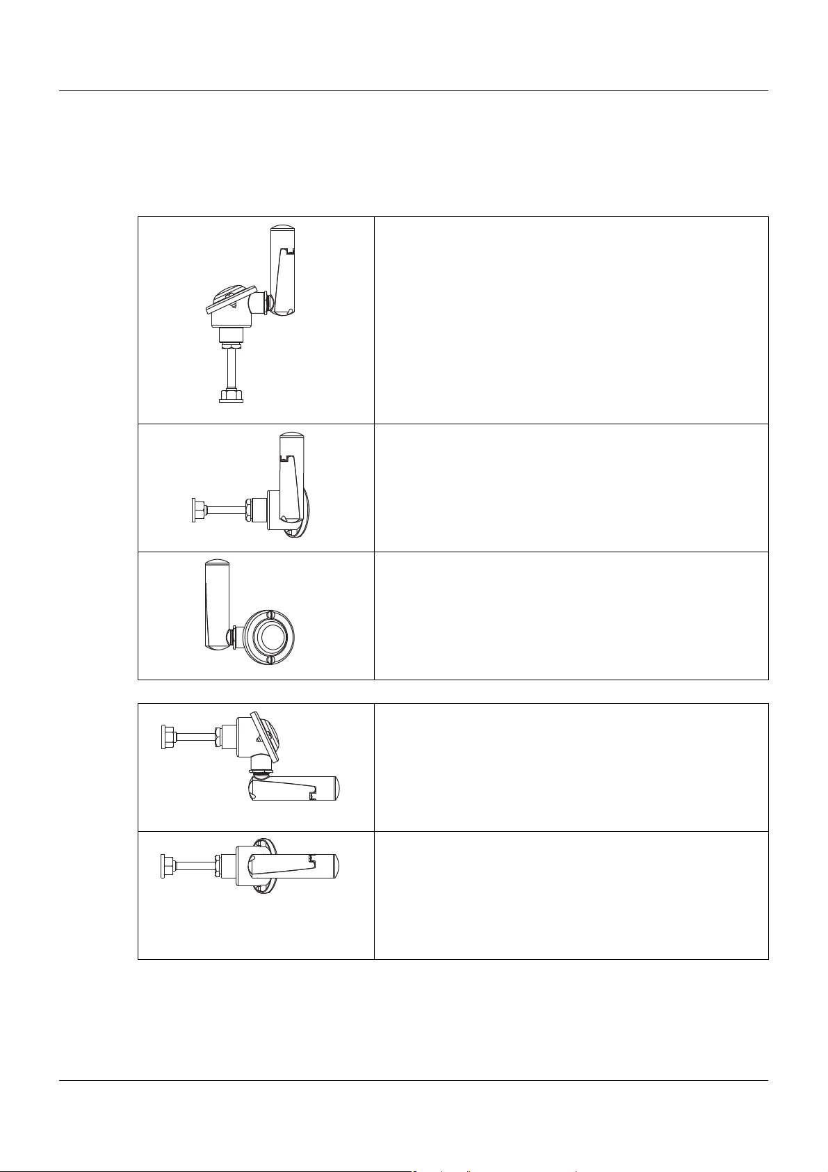
5.4 Aligning the antenna
The recommended and unfavorable antenna alignment possibilities are shown in the following
figure. The best possible reception is ensured when the recommended alignment possibilities
are used.
Recommended installation:
Connection head vertical and
antenna-battery case vertical to the top
Recommended installation:
Connection head horizontal and
antenna-battery case vertical to the top
Recommended installation:
Connection head horizontal and
antenna-battery case vertical to the top
Unfavorable installation:
Never install the antenna-battery case horizontally.
Unfavorable installation:
Never install the antenna-battery case horizontally.
22
Page 23

6.1 Safety information
• The electrical connection must only be carried out by qualified personnel.
• When installing and operating the transmitter ensure that no electro-static charging can
take place.
• The transmitter is not suitable for installation and application in explosion endangered areas.
• Never expose the transmitter to magnetic or electrical fields (e.g. caused by transformers,
walkie-talkies or electro-static discharge).
• An electrical connection deviating from the connection diagram can destroy the transmitter.
6 Electrical connection
23
Page 24

6 Electrical connection
(1)
(6)
(6)
(2)
(5)
(4)
(7) (8)
(3)
(9)
(10)
(11)
6.2 Connection elements and connectors
(1) SMB antenna connector (antenna connection) (7) Voltage supply socket (battery connection)
(2) Voltage supply connector (battery connection) (8) SMB antenna socket (antenna connection)
(3) Cable guide for antenna cable and voltage supply (9) Seal
(4) Probe connection (10) Locknut
(5) Setup connector (11) Battery lid screw
(6) Fastening holes for installation in the connection
head, form B
24
Page 25
6 Electrical connection
+-
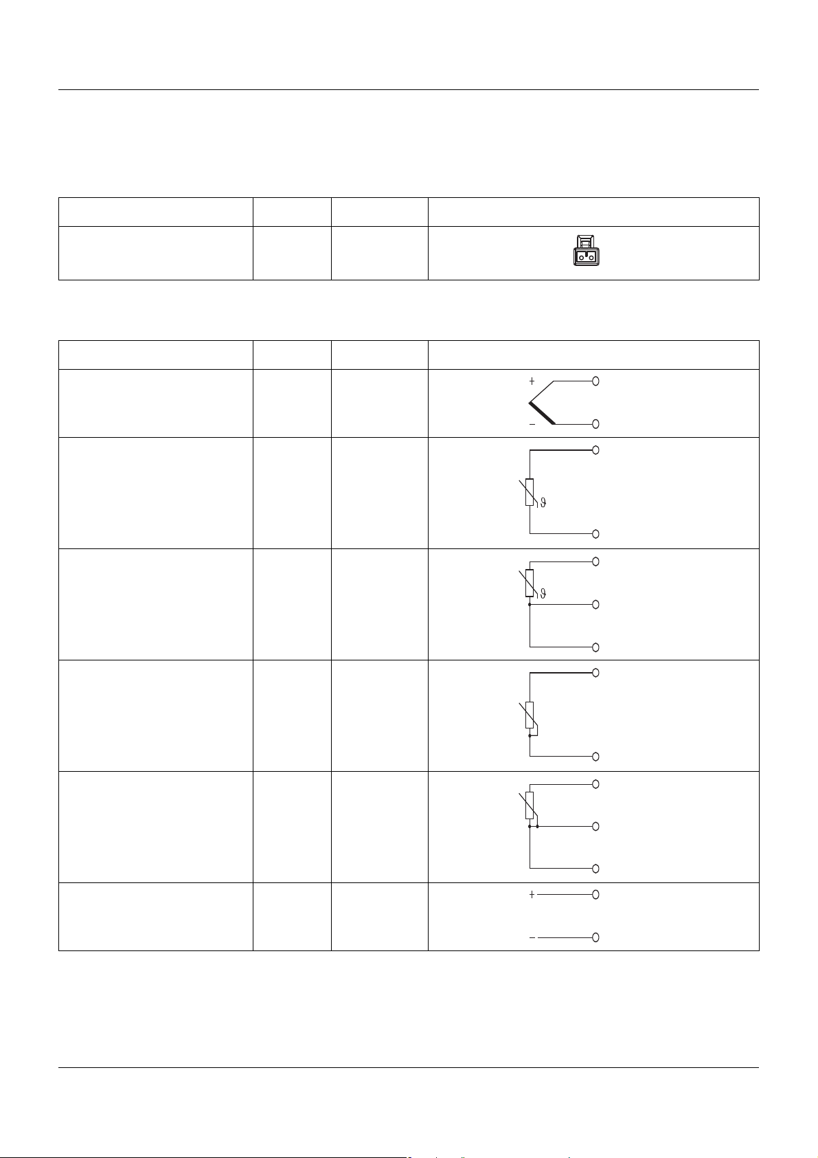
6.3 Connection diagram
6.3.1 Voltage supply
Connection Connector Terminals Symbol and terminal designation
Lithium battery, DC 3.6 V 2
6.3.2 Analog inputs
Connection Connector Terminals Symbol and terminal designation
Thermocouple 4 2 and 3 2
3
RTD temperature probe
2-wire circuit
RTD temperature probe
3-wire circuit
Potentiometer
2-wire circuit
Potentiometer
3-wire circuit
41 and 3 1
3
41 to 3 1
2
3
41 and 3 1
3
41 to 3 1
2
3
Voltage (0 ... 50 mV) 4 2 and 3 2
3
25
Page 26

6 Electrical connection
6.3.3 Output
Connection Connector Terminals Symbol and terminal designation
Antenna connector 1
6.3.4 Interface
Connection Connector Terminals Symbol and terminal designation
Setup 5
26
Page 27

7 Setup program
7.1 General information about the setup program
The setup program serves to configure probes and receivers by means of a PC. The configuration data can be archived on data carriers and printed.
Configurable parameters are:
•Probe ID
• Transmission interval
• Configuration of the probe used
The factory settings are:
• Probe ID consecutively
• Transmission interval (15s)
• Probe setting as per order specifications
(Example: Pt100 in 3-wire circuit, -200 ... +600 °C)
The connection between probe and PC is established via a PC interface (USB/TTL or TTL/
RS232 converter).
27
Page 28

7 Setup program
7.2 Hardware and software prerequisites
The following hardware and software prerequisites must be fulfilled for operation and the software installation:
Minimum configuration
•Intel Pentium III
• Microsoft Windows 2000 or XP
• 256 MB central memory
•CD drive
•Mouse
• a free USB port or
• a free serial port (depending on the interface used)
• 120 MB free hard-disk storage capacity
Recommended configuration
•Intel Pentium 4
• Microsoft Windows XP
• 512 MB central memory
1
or higher
1
2
2
Information about Windows 2000 or XP
If several users are managed on the computer, ensure that the user is logged in, who will work
with the program later. Ensure that the user has administrator rights while installing the software. Once installation is completed, the rights can be restricted again.
In the event of non-observance of this information, correct and complete installation cannot
be guaranteed!
28
1
Intel and Pentium are registered trademarks of the Intel Corporation.
2
Microsoft and Windows are registered trademarks of the Microsoft Corporation.
Page 29

7 Setup program
7.3 Establishing the connection between PC and probe
The connection between probe and PC is established via a PC interface TTL/RS232 converter
and adapter (socket) or USB/TTL converter and adapter (socket).
CAUTION!
Permanent interface operation!
The PC interface TTL/RS232 converter or USB/TTL converter is only designed for a time-limited interface connection.
Please ensure that the interface connection is disconnected and the probe correctly closed
once the setup data transfer is completed.
CAUTION!
Disconnect and remove the voltage supply!
Malfunctions can occur, if the connection between battery and transmitter is disconnected
while the setup connector is still connected.
Do not disconnect the battery from the transmitter as long as the setup connector is still connected.
CAUTION!
Low battery!
A low battery can lead to interface problems and result in an incorrect configuration or data
loss.
Please ensure that the battery used for the connection between PC and probe never reaches
the "Low battery" status.
29
Page 30

7 Setup program
(1)
(2)
(3)
(4)
TTL/RS232
(1) Laptop/PC (3) Adapter socket, 4-pin
(2) RS232 connector (4) Probe interface
For the setup via the TTL/RS232 converter, establish the following connections:
Step Activity
1 Insert the RS232 connector (2) into the laptop/PC (1).
2 Connect the adapter socket, 4-pin, (3) to the probe interface (4).
TIP!
For probe configuration, ensure that the probe is connected to the voltage supply of the antenna-battery case.
30
Page 31

USB/TTL
USB/TTL
(1)
(2)
(3)
(4)
(5)
(6)
(7)
(8)
7 Setup program
(1) Laptop/PC (5) Modular jack RJ-45
(2) USB connector (6) Adapter of the modular cable
(3) USB socket (7) Adapter socket, 4-pin
(4) USB/TTL converter (8) Probe interface
For the setup via the USB/TTL converter, establish the following connections:
Step Activity
1 Insert the USB connector (2) of the USB cable into the laptop/PC (1).
2 Insert the USB bush (3) of the USB cable into the connector of the USB/TTL converter (4).
3 Connect the RJ-45 connector (5) of the modular line to the RJ-45
socket of the USB/TTL converter (4).
4 Connect the 4-pin adapter socket (7) to the adapter of modular
line (6).
5 Connect the adapter socket, 4-pin, (7) to the probe interface (8).
TIP!
For probe configuration, ensure that the probe is connected to the voltage supply of the antenna-battery case.
31
Page 32

7 Setup program
7.4 Probe configuration
This chapter explains the configuration of a probe via the setup program. Prerequisite being
that the probe and the PC are connected via an interface.
7.4.1 Establishing the communication
A differentiation is made between two different way of proceeding when establishing the communication between probe and setup program:
• Establish the communication with "Device settings assistant“.
This is the case when the setup program is used for the first time
(list of devices empty).
• Establish the communication without "Device settings assistant“.
This is the case when the receiver/probe and setup program have already communicated
(list of devices with entries).
Establishing the communication using the assistant
How to proceed:
Step Activity
1 Start the setup program.
2 Select the "Establish connection" function in the "Data transfer“ menu.
The "Assistant for the device settings" appears.
3 Select the probe under the "Device version" and confirm by pressing "Continue".
4 Confirm the PC communication interface "Serial interface" by pressing "Continue".
5 Select the serial interface (e.g. COM1) and confirm with "Continue“.
6 Confirm the MU protocol (transmitter) by pressing "Continue".
7 Exit the assistant by pressing "Finish".
The device list with the selected probe appears.
8 Click on the "Connect" button.
The device list is closed, the assistant terminated and the communication between
probe and setup program established.
32
Page 33

Establishing the communication without using the assistant
How to proceed:
Step Activity
1 Start the setup program.
2 Select the "Establish connection" function in the "Data transfer“ menu.
The device list containing all devices entered is mapped in.
3 Select the desired probe by clicking with the left mouse key.
4 Click on the "Connect" button.
The device list is closed, the assistant terminated and the communication between
probe and setup program established.
7.4.2 Reading the current probe parameters
How to proceed:
Step Activity
7 Setup program
1 In the "File" menu select the "New" function.
The "Device assistant“ starts.
2 Confirm the "User-defined setting" by pressing the "Continue" button.
3 Select the "Frequency band" and confirm with "Continue".
4 Select the receiver variant and confirm by pressing "Continue".
5 Exit the overview of the selected settings by pressing "Finish".
The current settings are displayed in the setup program.
6 Select the desired probe from the navigation tree by clicking with the left mouse
key.
7 In the "Data transfer" menu select the "Data transfer from device" function.
8 Exit the inquiry "Save file" by selecting "Skip".
The current probe parameters are downloaded to the setup program.
7.4.3 Editing probe parameters
How to proceed:
Step Activity
1 Select the probe to be edited from the navigation tree by double clicking with the
left mouse key.
The "Probe configuration" is opened.
2 Edit the desired parameters.
3 Confirm editing with "OK“.
4 Save the parameters in the "File“ menu with the "Save“ function.
33
Page 34

7 Setup program
7.4.4 Transmitting new parameters to the probe
How to proceed:
Step Activity
1 In the "Data transfer" menu select the "Data transfer to device" function.
The current parameters are transmitted to the probe
2 Finish the communication between setup program and probe in the "Data transfer"
menu using the "Disconnect connection" function.
34
Page 35

7.5 ParametersOverview
Parameters Factory setting Value range/Selection
Probe ID inactive 1 ... 99999
Transmission interval 15 s 1 ... 3600 s
7 Setup program
Transmission frequency
Probe type RTD temperature
Sensor Pt100 depending on the probe type,
Connection type 3-wire circuit 3-wire circuit,
Lead resistance 0Ohm 0 ... 22 Ohm
Resistance RP 10000 Ohm 5 ... 10000 Ohm
Resistance R0 0Ohm 0 ... 4000 Ohm
TAG number 10-digit number, freely selectable
Information text 10-digit number, freely selectable
Installation date current date any date
868.4 MHz 868.4 MHz
Display only, cannot be edited!
Potentiometer,
probe
voltage,
thermocouple,
RTD temperature probe
Pt100 DIN EN 60751 -200 ... +600 °C
2-wire circuit
Only with 2-wire circuit!
Only for potentiometer probe type!
Only for potentiometer probe type!
TIP!
At a transmission interval of > 15 s, the probe transmits a so-called link telegram (after a setup transmission), i. e. the telegrams are transmitted at the factory-set interval of 15 s for a
period of 30 minutes, and only then at the set transmission interval.
TIP!
Once the setup connector is connected, the probe automatically transmits telegrams at a
transmission interval of 1s to ensure that changes can be immediately detected by the receiver. After the setup connector is removed, the telegrams are transmitted again at the set
transmission interval.
35
Page 36

7 Setup program
Term definition
Probe ID
The probe ID is an unmistakable ID with max. 5 characters which is recognized by the receiver.
The ID can be individually changed, for example, to achieve a better overview of a system.
Ensure that an ID is not used simultanously by two probes within the reception range to avoid
malfunctions.
Transmission interval
This parameter is used to define the time intervals used to transmit data to a receiver. The setting of the "Transmission interval" parameter affects the battery service life. For this reason,
act with caution and do not only consider the transmission quality when selecting the interval.
Transmission frequency
The transmission frequency defines the frequency band used to transmit data to a receiver.
The transmission frequency is defined at 868.4 MHz for Europe because special regulations
are defined concerning transmission interval and transmission capacity for the ISM band (Industrial, Scientific and Medical Band).
36
Page 37

8 Supplement
8.1 Technical data
8.1.1 Analog inputs
Thermocouples
Designation Standard Measuring range Measuring accuracy
Fe-CuNi „L“ DIN 43710 -200 to +900 °C ± 0.1 %
Fe-CuNi „J“ DIN EN 60584 -210 to +1200 °C ± 0.1 % from -100 °C
Cu-CuNi „U“ DIN 43710 -200 to +600 °C ± 0.1 % from -100 °C
Cu-CuNi T DIN EN 60584 -270 to +400 °C ± 0.1 % from -150 °C
NiCr-Ni K DIN EN 60584 -270 to +1372 °C ± 0.1 % from -80 °C
NiCr-CuNi „E“ DIN EN 60584 -270 to +1000 °C ± 0.1 % from -80 °C
NiCrSi-NiSi „N“ DIN EN 60584 -270 to +1300 °C ± 0.1 % from -80 °C
Pt10Rh-Pt „S“ DIN EN 60584 -50 to +1768 °C ± 0.15 % from 20 °C
Pt13Rh-Pt „R“ DIN EN 60584 -50 to +1768 °C ± 0.15 % from 50 °C
Pt30Rh-Pt6Rh „B“ DIN EN 60584 0 to 1820 °C ± 0.15 % from 400 °C
W5Re-W26Re „C“ 0 to 2320 °C ± 0.15 %
W3Re-W25Re „D“ 0 to 2495 °C ± 0.25 %
W3Re-W26Re 0 to 2400 °C ± 0.15 %
Chromel-Copel -200 to +800 °C ± 0.1 % from -80 °C
Chromel-Alumel -200 to +1372 °C ± 0.1 % from -80 °C
PLII (Platinel II) 0 to 1395 °C ± 0.15 %
MoRe5-MoRe41 0 to 2000 °C ± 0.2 %
Cold junction Pt1000 internal
Cold junction accuracy ± 1 K
RTD temperature probe
Designation Standard Measuring range Measuring accuracy
Pt100
(TK value = 3.85 × 10
1/K)
Pt500
(TK value = 3.85 × 10
1/K)
DIN EN 60751 -100 to +200 °C
-3
DIN EN 60751 -100 to +200 °C
-3
-200 to +600 °C
-200 to +600 °C
± 0.1 K
± 0.2 K
± 0.1 K
± 0.2 K
Pt1000
(TK value = 3.85 × 10
1/K)
Ni 100
(TK value = 6.18 × 10
1/K)
DIN EN 60751 -100 to +200 °C
-3
DIN 43760 -60 to +250 °C ± 0.2 K
-3
-200 to +600 °C
± 0.1 K
± 0.2 K
37
Page 38

8 Supplement
Designation Standard Measuring range Measuring accuracy
Ni 500
(TK value = 6.18 × 10
1/K)
Ni 1000
(TK value = 6.18 × 10
1/K)
Pt100
(TK value = 3.917 × 10
3
1/K)
Pt50
(TK value = 3.91 × 10
1/K)
Pt100
(TK value = 3.91 × 10
1/K)
Cu50
(TK value = 4.26 × 10
1/K)
Cu100
(TK value = 4.26 × 10
1/K)
DIN 43760 -60 to +150 °C ± 0.2 K
-3
DIN 43760 -60 to +150 °C ± 0.2 K
-3
JIS 1604 -100 to +200 °C
-
ST RGW 1057
-3
1985
GOST 6651-
-3
94 A.1
GOST 6651-
-3
94 A.4
GOST 6651-
-3
94 A.4
-200 to +600 °C
-200 to +600 °C ± 0.2 K
-100 to +200 °C
-200 to +600 °C
-50 to +200 °C ± 0.2 K
-50 to +200 °C ± 0.2 K
± 0.1 K
± 0.2 K
± 0.1 K
± 0.2 K
Connection type 2-wire or 3-wire circuit
Sensor lead resistance
2-wire circuit Measuring resistance + ≤ 22 Ω total line resistance
3-wire circuit 11 Ω per line
Probe current < 0.5 mA
Lead compensation Not required for 3-wire circuit (max. admissible 11 Ω per line).
Can be configured on the probe with 2-wire circuit (≤ 22 Ω).
Potentiometer
Designation Measuring range Measuring accuracy
Potentiometer < 400 Ω
≥ 400 Ω to ≤ 4000 Ω
> 4000 Ω to ≤ 10000 Ω
± 400 mΩ
± 4 Ω
± 10 Ω
Connection type 2-wire or 3-wire circuit
Sensor lead resistance
2-wire circuit ≤ 22 Ω
3-wire circuit ≤ 11 Ω per line
38
Page 39

8 Supplement
Voltage
Designation Measuring range Measuring accuracy
Voltage 0 to 50 mV ± 0.1 %
8.1.2 Output (radio transmission)
Probe ID max. 5-digit ID, factory-set, can be configured customer-spe-
cific
Transmission interval adjustable from 1 to 3600 s (ex-factory 15 s)
Transmission frequency ISM band 868.4 MHz (Europe)
Transmission capacity +10 dBm
Open air range Max. 300 m when using the antenna wall holder of the
receiver and 3 m long antenna cable. When installing the
antenna directly onto the receiver, a reduced range of approx.
40% must be taken into account.
Output signal
Thermocouple Voltage (mV)
RTD temperature probe Resistance (Ω)
Potentiometer Percent (%) and resistance (Ω)
Voltage Voltage (mV)
Configuration with setup program
Configurable parameters Probe ID (max. 5-digit ID) and transmission interval
8.1.3 Electrical data
Voltage supply
Lithium battery Rated voltage: 3.6 V, rated capacity: 2.2 Ah
Size AA
Operating life approx. 1 year with the factory-set values (transmission inter-
val = 15s) and at room temperature(fast transmission interval
and high or low ambient temperature reduce the battery
operating life)
Battery change only use the lithium battery available as accessories
39
Page 40

8 Supplement
8.1.4 Environmental influences
Transmitter in the B head with antenna-battery case
Ambient temperature range -30 ... +85 °C
Storage temperature range / storage
humidity
Temperature coefficient
Thermocouple ≤ ± 0.005 % / K deviation 22 °C plus accuracy of the cold
RTD temperature probe ≤ ± 0.005 % / K deviation from 22 °C
Potentiometer ≤ ± 0.01 % / K deviation from 22 °C
Voltage ≤ ± 0.005 % / K deviation from 22 °C
Climate class 10 cycles at 10 °C / 80 °C, as per IEC 68-2-30,
Vibration resistant as per GL characteristic line 2
Admissible mechanical shock resistance 10 g / 6 ms, as per DIN IEC 68-2.29
Electromagnetic compatibility (EMC) as per DIN EN 61326-1
Interference emission Class B
Interference immunity Industrial requirements
Radio frequency spectrum ETSI EN 300 220-1 (V 2.3.1) and ETSI EN 300 220-2 (V 2.3.1)
a
All accuracy values in % refer to the maximum measuring range.
a
-40 ... +85 °C / rel. humidity ≤ 95 %
junction
rel. humidity 95 %, during operation
8.1.5 Case
Tran sm it te r
Type Plastic case to be installed in connection head, form B
Material Polycarbonate
Flammability class UL 94 V2
Dimensions
Diameter 44 mm
Height with/without connectors 31 mm / 27 mm
Protection type IP65, when installed (with suitable head, form B)
Connections
Sensor 3-pole connection terminal RM 5 mm, conductor cross-sec-
tion 1.5 mm²
Antenna SMB connector
Voltage supply 2-pole multi-pin connector RM 2.54 mm
Setup 4-pin connector
Weight approx. 35 g
40
Page 41

8 Supplement
Antenna-battery case
Type Plastic case with M20x1.5 thread for connection head, form
B
Material Polyetherimide
Flammability class UL 94 HB or UL 94 V-0
Dimensions
Diameter 30 mm
Height 115 mm
Protection type IP65, as per DIN EN 60529
Connection
Antenna SMB inlet, 50 Ω
Battery connection 2-pole connector RM 2.54 mm
Operating position preferably vertical (optimum alignment to the receiver
antenna)
Weight (including battery) approx. 80 g
41
Page 42

8 Supplement
42
Page 43

Page 44

JUMO GmbH & Co. KG
Street address:
Moritz-Juchheim-Straße 1
36039 Fulda, Germany
Delivery address:
Mackenrodtstraße 14
36039 Fulda, Germany
Postal address:
36035 Fulda, Germany
Phone: +49 661 6003-0
Fax: +49 661 6003-607
e-mail: mail@jumo.net
Internet: www.jumo.net
JUMO Instrument Co. Ltd.
JUMO House
Temple Bank, Riverway
Harlow, Es
sex CM20 2DY, UK
P
hone: +44 1279 635533
Fax: +44 1279 635262
e-mail: sales@jumo.co.uk
Internet: www.jumo.co.uk
JUMO Process Control, Inc.
8 Technology Boulevard
Canastota, NY 13032, USA
Phone: 315-697-JUMO
1-800-554-JUMO
Fax: 315-697-5867
e-mail: info@jumo.us
Internet: www.jumo.us
 Loading...