

Page 1

Inductive
conductivity transmitter
in stainless steel housing
JUMO CTI-750
Type 202756
B 20.2756.0.1
Operating manual
11.07/00488788
Page 2

Page 3

Contents
1 Typographical conventions ...................................................... 8
1.1 Warning signs ..............................................................................................8
1.2 Attention-drawing signs ...............................................................................8
2 General ....................................................................................... 9
2.1 Foreword ......................................................................................................9
2.2 Structure of the JUMO CTI-750..................................................................10
3 Inductive conductivity measurement .................................... 11
3.1 Field of application .....................................................................................11
3.2 Function .....................................................................................................12
4 Identifying the device ............................................................. 13
4.1 Type nameplate .........................................................................................13
4.2 Type declaration ........................................................................................14
4.3 JUMO CTI-750 as "Head transmitter" ........................................................14
4.4 JUMO CTI-750 as "Transmitter with separate sensor" .............................15
5 Device description .................................................................. 17
5.1 Technical data, transmitter ......................................................................17
6 Assembly .................................................................................. 21
6.1 General ...................................................................................................... 21
6.2 Dimensions / Process connections, head transmitter ...............................22
6.3 JUMO CTI-750 with separate sensor ........................................................24
6.4 Assembly examples ...................................................................................28
7 Installation ............................................................................... 30
7.1 General ......................................................................................................31
8 Setup program ........................................................................ 34
8.1 Function .....................................................................................................34
9 Commissioning ....................................................................... 35
9.1 Head transmitter or transmitter with separate sensor ...............................35
9.2 Replacement sensor ..................................................................................35
Page 4

Contents
10 Operation ................................................................................. 36
10.1 Operating elements ....................................................................................36
10.2 Principle of operation .................................................................................38
10.3 Principle .....................................................................................................40
10.4 Measurement mode ...................................................................................41
10.5 Operator level .............................................................................................41
10.6 Administrator level .....................................................................................49
10.7 Calibration level ..........................................................................................51
10.8 The desalination function ...........................................................................52
11 Calibrating ............................................................................... 56
11.1 General ...................................................................................................... 56
11.2 Calibration of the relative cell constant ......................................................56
11.3 Calibration of the temperature coefficient of the measurement solution ...57
12 Maintenance ............................................................................ 65
12.1 Cleaning the conductivity sensor ...............................................................65
13 Rectifying errors and faults ................................................... 66
13.1 Device inspection .......................................................................................66
14 Annex ....................................................................................... 72
14.1 Before configuring .................................................................................. 72
Page 5

5
A
A/D-converter 17
Sediments 11, 65
Desalination reduction 53
DESALINATION FUNCTION 48
Desalination function 48, 52, 74
Desalination function: Start 48
Desalination function: Stop 48
Desalination 11
Desalination valve 52
REDUCTION 48
Reduction 74
DISTANCE 47
Distance 74
Alarm window 47
Analog output in case of "Alarm" 18–19
Connection 34
Connection layout of the transmitter 33
Weld-on threaded connector28
Display 17
OUTPUT BINARY 46
Output binary 74
OUTPUT CONDUCTIVITY 44
Output conductivity 72
OUTPUT TEMPERATURE 45
Output temperature 73
Outputs 33
Output signal 18
Output signal, temperature 19
SWITCHOFF DELAY 48
Switchoff delay 74
B
Operating in levels 40
Operation principle 38
IN CASE OF ALARM 44–45
In case of alarm 73
IN CASE OF ALARM / CALIB. 47
in case of alarm / at the time of calibration 74
IN CASE OF HOLD 47
in case of Hold 74
IN CASE OF CALIBRATION 44, 46
In case of calibration 73, 74
LIGHTING 49
Lighting 75
Calculation of a temperature coefficient 60
REFERENCE TEMPERATURE 42
Reference temperature 72
Binary inputs 33
Biocide 52
Burden 18–19
C
CIP 11
CIP-Process 11
D
DOSING TIME 48
Dosing time 74
Pressure 20
E
Levels of the Administrator level 50
MOUNTING FACTOR 43
Mounting factor 21, 72
Installation position 21
Installation variants 22
INPUT BINARY 48
input binary 74
INPUT CONDUCTIVITY 42
Input conductivity 72
INPUT TEMPERATURE 45
Input temperature 73
UNIT 45
Unit 73
SWITCH-OFF DELAY48
Switch-off delay 74
Setting parameters 48
Electrical connection 17, 30
Electromagnetic compatibility 30
Removing the pigmenting 32
Determining the TC-curve 60
explosion-endangered areas 30
F
Error possibilities 66
FILTERING TIME 43, 45
Filtering time 72, 73
FUNCTION 46, 48
Function 20, 74
G
galvanic separation 34
Housing 17
Accuracy 19–20
DEVICE DATA 49
Device data 75
Weight 17
LIMITING VALUE 47
Limiting value 74
H
MANUAL OPERATION 44, 46–47
Page 6

6
Manual operation 73–74
MANUAL VALUE 44, 46
Manual value 73–74
Date of manufacture 13
Attention-drawing signs 8
Hold function 48
HYSTERESIS 47
K
CALIBR.-INTERVAL 43
Calibration interval 72
Calibration timer 18
Characteristic 19
Compensation range 19
Configurable parameters 34
Configuring 72
CONTRAST 49
Contrast 75
CONCENTR. RANGE43
CONCENTR. MEASUREMENT 43
Concentration measurement 18, 72
L
LCD INVERSE 49
LCD inverse 75
Limit comparator 46
Solvent 65
M
MANUAL SPECIFICATION 45
Manual specification 73
Material 20
MEASUREMENT RANGE 42
Measurement range 72
MEASUREMENT RANGE 1 42
Measurement range, sensor 20
Measurement range / Temperature coefficient
switching
48
Transmitter head 24
Measurement process 11
MEASUREMENT VALUE ACQUISITION 45
Measurement value acquisition 73
Installation location 21
N
natural 20
natural water 20
non-linear temperature coefficient 60
O
OFFSET 43, 45
Offset 72–73
P
Parameters, configurable 34
Password 49
Polarization 11
PULSE DURATION 48
Pulse duration 74
R
Reference fluid 70
Reference measuring instrument 71
Reference temperature 19
REL. CELL CONSTANT 42
Relative cell constant 72
S
Breaking capacity of the semiconductor relay
17
System of protection 17
Sensor part 25
Service-Hotline 9
Setup interface 34
SAFETY VALUE 44, 46
Safety value 73, 74
SIGNAL TYPE 44–45
Signal type 72–73
SCALING START 44–45
Scaling start 73
SCALING END 44–45
Scaling end 73
Sunlight radiation 21
Voltage supply 17, 33
LANGUAGE 49
Language 75
T
Keyboard lock 48
TEMP. COEFFICIENT 42
TEMP. COMPENSATION 42
Temperature of the measurement medium 20
Temperature acquisition 19
Temperature coefficient 19, 72
Temperature compensation 72
Temperature compensation with the TC-curve
61
Temperature measurement range 19
TC-curve 61
U
Influence of ambient temperature 18–19
reconfigure 72
Page 7

7
V
LOCKING TIME 48
Locking time 74
Pre-calculated values 69
W
Warning signs 8
Resistant loop 67
Wiping contact 47
Z
CELL CONSTANT 42
Cell constant 72
permissible storage temperature 17
permissible ambient temperature 17
Page 8

8
1 Typographical conventions
1.1 Warning signs
1.2 Indicative signs
Caution
This sign is used if, by carefully following or not following instructions, harm to
persons can occur
Caution
This sign is used if, by carefully following or not following instructions, dam-
age to devices or data can occur
Note
This sign is used when your attention is to be drawn to something special.
abc
1
Footnote
Footnotes are remarks that refer. to specific places in the text. Footnotes
consist of two parts:
Flag in the text and footnote text.
The flagging in the text is done by superscript serial numbers.
✱ Action indication
This sign indicates that an activity to be carried out is being described.
The individual work steps are marked by this star.
Example:
✱ Loosen the crosshead screws..
Page 9

9
2 General
2.1 Foreword
Please read the operating manual before you commission the device. Store
the operating manual at a place that is accessible for all users at all times.
Please help us to improve this operating manual.
We would be grateful for your suggestions.
Telephone(06 61) 60 03-7 14
Telefax (06 61) 60 03-6 05
All the required settings are described in this manual. Should there
be any difficulties nonetheless at the time of commissioning, we
request you not to carry out any impermissible manipulations. You
could render your warranty entitlement null and void.
Please get in touch with the nearest branch or with the head office.
In case of technical queries
Service-Hotline:
Telephone:(06 61) 60 03-3 00 or (06 61) 60 03-6 53
Telefax: (06 61) 60 03-88 13 00 or (06 61) 60 03-88 16 53
E-mail: Service@jumo.net
Page 10

2 General
10
2.2 Structure of the JUMO CTI-750
Examples
(1) Transmitter (4) Inductive conductivity measuring
probe
(2) Process connection (5) with or without graphics LC-display
(3) Temperature sensor
Model:
Transmitter and
conductivity measuring
probe combined,
type 202756/xx...
Model:
Transmitter w ith
separate sensor,
type 202756/xx...
(2)
(1)
(3)
(1)
(2)
(4)
(5)
(4)
(3)
Page 11

11
3 Inductive conductivity measurement
3.1 Range of Applications
General The inductive measurement process allows a mostly maintenance-free acqui-
sition of the specific conductivity even in difficult medium conditions. In contrast to the conductive measurement process, problems like electrode
replacement and polarization do not occur.
Brief description
The device is used for the measurement / control of the conductivity / concentrations of liquid media. Using it is particularly recommended in media in which
significant deposits from carried dirt, oil grease or of lime and gypsum are
expected. The integrated temperature measurement makes exact and fast
temperature compensation possible, which is particularly important for the
measurement of the conductivity. Additional functions such as the combined
switching of the measurement range and temperature coefficient make possible the optimum use in case of CIP-processes.
Two integrated switching outputs can be freely programmed for limit value
monitoring or conductivity / concentration and /or temperature. In addition,
alarm and control tasks (desalination) can be assigned.
Operation is either via a membrane keyboard and a plain text graphical display
(user language can be changed) or via a comfortable PC-Setup program. By
simply turning the housing cover, reading the display is possible both in case
of installation in vertical or horizontal pipes. By means of the Setup program,
the device configuration data can also be saved and printed for plant documentation purposes. To prevent manipulation, the device can also be supplied
without a keyboard / display. In this case, the Setup program is required for
programming.
The JUMO CTI-750 can be supplied as a combine device (transmitter and
measuring cell in one device) or as a shouldered version (transmitter and measuring cell connected by cables). The separate version is particularly suitable
for plants with intense vibrations and/or intense temperature radiation at the
measurement location or for installation at not easily accessible places.
Typical usage
fields
- CIP-cleaning (CIP = Clean In Place / Process)
- Concentration monitoring or chemical dosing
- Foodstuffs beverages and pharmaceutical industries
-Product monitoring (phase separation, Product / Product mixture /
Water) in the beverage industry, breweries, dairies
- Control (e.g. phase separation of cleaners / rinsing water of
cleaning processes e.g.. bottle cleaning plants and in case of container
cleaning)
Page 12

3 Inductive conductivity measurement
12
3.2 Function
of the transmitter
The JUMO CTI-750 transmitter is conceived for use at the location. A robust
housing protects the electronics and the electrical connections from aggressive ambient influences (system of protection IP 67). In the standard version,
the device has one analog signal input for the conductivity / concentration and
the temperature. The further processing of the standard signals can take place
in suitable display / control devices or, e.g. directly in a PLC.
The output signals are galvanically separated from one another and from the
measurement medium.
of the measuring cell
The measurement of the conductivity takes place with an inductive probe. A
sinusoidal AC is supplied to the transmitting coil. Depending on the conductivity of the liquid to be measured, a current is induced in the receiver coil. The
current is proportional to the conductivity of the medium. The cell constant of
the inductive probe is geometry-dependent. In addition, the cell constant can
be influenced by parts in its immediate vicinity.
(1) Plastic body (4) Measurement medium
(2) T-shaped flow channel (5) Temperature sensor Pt100
(3) Fluid loop
(2)
(1)
(3)
(4)
(5)
Page 13

13
4 Identifying the device
4.1 Type nameplate
on the
transmitter
on the connecting
cable
(only in case of
separate sensor)
JUMO GmbH & Co. KG
Fulda, Germany
www.jumo.net
JUMO CTI-750
Typ: 202756/16-607-0000-82/000
VARTN: 20/00445843
F-Nr.: 00909467 01 0 0745 0001
DC 19...31 V 3W
ⱕ
F-Nr.: 00909467 01 0 0517 0001
In the case of devices with a separate sensor (base type supplementation (2)
66), for every instrument, the transmitter and the separate sensor are matched
to one another at the factory.
When connecting the components, ensure that the production number of the
external sensor (on the flag tag on the connecting cable) is identical to the production number of the transmitter (on the nameplate).
The date of manufacture is encrypted in the "F-No." :
0517 means year of manufacture 2005 / calendar week 17
Page 14

4 Identifying the device
14
4.2 Type explanation
4.3 JUMO CTI-750 as "Head-mounted transmitter"
1
Only in conjunction with additional code 767 (measuring cell material
PEEK).
2
If required, M12-plug / -sockets, additional code 580 should be ordered.
3
Specify additional codes in succession separated by a comma.
4
Assembly material (mounting brackets) not part of the scope of supply.
(1) Basic type
202756 JUMO CTI-750
Inductive transmitter / switching device
for conductivity / concentration and temperature
(2) Basic type supplementation
16 Head-mounted transmitter in stainless steel housing
with display / keyboard
(3) Process connection
o 107 Stud thread G1 1/4A
o 108 Stud thread G1 1/2A
o 110 Stud thread G2A
o 606 Screwed pipe connection DN40, DIN 11 851
(MK DN50, milk cone)
o 607 Screwed pipe connection DN50, DIN 11 851
(MK DN40, milk cone)
o 608 Screwed pipe connection DN65, DIN 11 851
(MK DN65, milk cone)
o 609 Screwed pipe connection DN80, DIN 11 851
(MK DN80, milk cone)
o 617 Clamp 2 1/2"
4
o 686 VARIVENT® DN40/50
1
o 690 SMS 2"
(4) Immersion length
o 000 see "Dimensions / Process connections (head-
mounted transmitter"
(5) Electrical connection
o82Cable glands
o 83 M12-plug / -sockets
(instead of the cable glands)
2
o 84 Two cable glands M16 and a dummy plug
(6) Extra codes
3
000 None
o 268 Temperature sensor inside
X 767 Measuring cell material PEEK
X 768 Measuring cell material PVDF
o 844 Voltage supply AC 24 V
(1) (2) (3) (4) (5) (6)
Ordering key / - - - / , ...
Ordering example 202756 / 16 - 607 - 000 - 82 / 000
Page 15

15
4 Identifying the device
4.4 JUMO CTI-750 as "Transmitter with separate sensor"
(1) Basic type
202756 JUMO CTI-750
Inductive transmitter / switching device
for conductivity / concentration and temperature
(2) Basic type supplementation
26 Transmitter in stainless steel housing, with display / keyboard
(without sensor)
5
66 Transmitter in stainless steel housing, with display / keyboard includ-
ing sensor (cable length 10 m)
85 Replacement sensor with 10 m cable
1, 5
for transmitter in stainless steel housing
(3) Process connection
X 000 not available
o o o 107 Stud thread G1 1/4A
o o o 108 Stud thread G1 1/2A
o o o 110 Stud thread G2A
o o o 606 Screwed pipe connection DN40, DIN 11 851 (MK DN40, milk cone)
o o o 607 Screwed pipe connection DN50, DIN 11 851 (MK DN50, milk cone)
o o o 607 Screwed pipe connection DN65, DIN 11 851 (MK DN65, milk cone)
o o o 607 Screwed pipe connection DN80, DIN 11 851 (MK DN80, milk cone)
o o o 617 Clamp 2 1/2"
1
ooo 686 VARIVENT® DN40/50
2
o o o 690 SMS 2"
5
o o 706 Submerged version
6
(4) Immersion length
X 0000 see "Dimensions / Process connections (separate sensor)"
X o o 0500 0500 mm
X o o 0000 1000 mm
X o o 0000 1500 mm
X o o 0000 2000 mm
X o o xxxx Special length (in grid of 250 mm; e.g. 0250; 0750; 1250; 1750)
(5) Electrical connection
X 21 Fixed cable with M12-socket at separate sensor
o o 82 Cable glands on operating part
o o 83 M12-plug / sockets on operating part
3
o o 84 Two cable glands M16 and a dummy plug
(6) Extra codes
4
X X X 000 no extra code
o o 268 Temperature sensor inside
o o 580 1 set M12-plug / sockets
X X X 767 Measuring cell material PEEK
X X X 768 Measuring cell material PVDF
o o 844 Voltage supply AC 24 V
Page 16

4 Identifying the device
16
1
Assembly material (Union / grooved nut, mounting bracket) not part of
scope of supply. If required, please order as well, see accessories.
2
Only in conjunction with additional code 767 (measuring cell material
PEEK).
3
If required, M12-plug / -sockets, additional code 580 should be ordered.
4
Specify additional codes in succession separated by a comma.
5
An equalizing set is indispensable for commissioning. If not available,
please order as well, see Accessories.
6
Only in conjunction with additional code 768 (measuring cell material
PVDF).
(1) (2) (3) (4) (5) (6)
Ordering key / - - - / , ...
Ordering example 202756 / 66 - 607 - 1000 - 82 / 767
Page 17

17
5 Device description
5.1 Technical data, transmitter
5.1.1 General
A/D-converter Resolution: 15-bit
sampling time:500 ms = 2 measurements/s
Voltage supply For operation on SELF- or PELV-circuits
Standard production feature:
DC 19…31 V (nominal DC 24 V), the device has reverse polarity protection
Ripple: < 5%
Power drawn with display: ≤ 3 W
Power drawn without display: ≤ 2.6 W
In case of extra code 844:
AC 24 V ±10%
Breaking capacity of the semiconductor relay
U< 50 V AC/DC
I ≤ 200 mA
electrical connection
Threaded plug terminals 2.5 mm
2
or M12-plug/ sockets
Display (option) Graphic-LCD with background lighting; Contrast adjustable
dimensions: 62 x 23 mm
permissible
ambient temperature
(transmitter)
-5…+50°C
max. 93% rel. atmospheric humidity, without thawing
permissible
storage temperature
(transmitter)
-10…+65°C
max. 93% rel. atmospheric humidity, without thawing
System of protection
(transmitter)
IP 67
Housing Stainless steel, material no. 1.4305
Weight depending on the model and process connection
about 2.4 kg
Page 18

5 Device description
18
5.1.2 Conductivity-/ Concentration transmitter
Concentration
measurement
(implemented in
the device software)
- NaOH (sodium hydroxide solution)
0...15 % by weight or 25...50 % by weight
- HNO
3
(nitric acid); pay attention to the chemical resistance of the sensor!
0...25 % by weight or 36...82 .% by weight
- Customer-specific concentration curve
freely programable via the setup program (see "Special functions")
Calibration
timer
adjustable: 0...999 days (0 = off)
Output signal
conductivity /
concentration
0...10 V / 10...0 V
2...10 V / 10...2 V
0...20 mA / 20...0 mA
4...20 mA / 20...4 mA
The output signal is freely scalable.
Load ≤ 500 Ω for current output
≥ 2kΩ for voltage output
Influence of
ambient temperature
≤ 0.1%/K
Analog output
in case of
"Alarm"
Low (0 mA / 0 V / 3.4 mA / 1,4 V) or
High (22.0 mA / 10,7 V) or
a fixed value that can be set (safety value)
Measurement
ranges
Four measurement ranges can be selected.
One of these measurement ranges can be activated via an external switch or a
PLC .
Measurement ranges, transmitter
Accuracy
(in % of the start -
of measurement range)
0...500 µS/cm
≤0.5%
0...1000 µS/cm
0...2000 µS/cm
0...5000 µS/cm
0...10 mS/cm
0...20 mS/cm
0...50 mS/cm
0...100 mS/cm
0...200 mS/cm
0...500 mS/cm
0...1000 mS/cm
0...2000 mS/cm
1
Page 19

19
5 Device description
1
not temperature-compensated
Note:
The overall accuracy is formed from the accuracy of the transmitter + the
accuracy of the sensor.
5.1.3 Temperature transmitter
Temperature
acquisition
manual -20.0...25.0...150°C / °F
or
automatic
Temperature
measurement
range
-20...150°C / °F
Characteristic linear
Accuracy ≤ 0.5% of the measurement range
Influence of
ambient temperature
≤ 0.1%/K
Output -signal
temperature
0...10 V / 10...0 V
2...10 V / 10...2 V
0...20 mA / 20...0 mA
4...20 mA / 20...4 mA
The output signal is freely scalable.
Load ≤ 500 Ω for current output
≥ 2 kΩ for voltage output
Analog output
in case of
"Alarm"
Low (0 mA / 0 V / 3.4 mA / 1,4 V) or
High (22.0 mA / 10,7 V) or
a fixed value that can be set (safety value)
5.1.4 Temperature compensation
Reference temperature
15...30°C adjustable
Temperature
coefficient
0.0...5.5 %/K adjustable
Page 20

5 Device description
20
Compensation
range
-20...150°C
Function - Linear compensation (constant temperature coefficient).
This type of compensation can be applied with acceptable for many normal
types of water. The temperature coefficient used is then about 2.2 %/K.
- Natural water (DIN EN27888 or ISO 7888).
In this case, a so-called non-linear temperature compensation is applied.
According to the above standard, the corresponding type of compensation
can be applied in the case of natural ground waters, spring waters and
above-ground waters.
The conductivity of the water is compensated in the range from 0°C to
36°C.
- Not linear (for learning function, see special functions)
Here, the actual flow of the temperature coefficient during a heating-up or
cooling process is determined with the transmitter.
5.1.5 Sensor
Material PEEK (Polyetheretherketone) or
PVDF (Polyvenylidenfluoride)
Note!:
Temperature, pressure and measurement medium influence the life of the
measuring cell
Temperature of
the measurement medium
-10 ... +120°C
short-term 140°C (sterilization)
Pressure max. 10 bar
1
not temperature-compensated
Measurement range
Sensor
Accuracy
(in % of the start -
of measurement range)
0...500 µS/cm
≤1%
0...1000 µS/cm
0...2000 µS/cm
≤0.5%
0...5000 µS/cm
0...10 mS/cm
0...20 mS/cm
0...50 mS/cm
0...100 mS/cm
0...200 mS/cm
0...500 mS/cm
0...1000 mS/cm
≤1%
0...2000 mS/cm
1
Page 21

21
6 Installation
6.1 General
Installation
location
The compatibility of the material with the measurement medium must be
checked by the customer.
Ensure easy accessibility for subsequent calibration.
The fastening must be secure and low-vibration.
Avoid direct sunlight.
It is necessary to pay attention to a good flow through and around the sensor
(1).
When installing in a pipe, a minimum distance of 20 mm must be maintained
from the sensor to the pipe wall.
If these minimum distances cannot be maintained, the parameter "Mounting
factor" can be used to achieve limited equalization.
In immersion operation in a basin, an installation location that is representative
for the typical conductivity or concentration must be provided.
Mounting location
The JUMO CTI-750 can be mounted in any position.
Screwing in and
unscrewing the
separate sensor
No cable twisting should occur.
Avoid tensile forces on the cable, especially jerky pulling.
Sensor details
(1)
Stainless steel sleeve: Material
1.4571
Sealing: FPM
Page 22

6 Installation
22
6.2 Dimensions / Process connections, head transmitter
Installation variants
Process
connection
(1.4301)
71
130
207
40
84
177
130
71
56
37
Process
connection
(1.4301)
71
130
224
20
60
104
G
Model with
process connection 607
MK DN50
Model with
process connection 617
Clamp 21/2"
(mounting bracket not part
of scope of supply)
Process
connection
Slotted union nut
F50
(1.4301)
71
84
40
212
130
Model with process connection
107 = Stud thread G1 1/4A
108 = Stud thread G1 1/2A
110 = Stud thread G2A
Version with
process connection 686
VARIVENT® DN50
(mounting bracket not
in scope of supply)
Page 23

23
6 Installation
Process
connection
(1.4301)
Ring nut
SMS 2"
(1.4301)
130
71
215
84
40
Model with
process connection 690
SMS 2"
Page 24

6 Installation
24
6.3 JUMO CTI-750 with separate sensor
Tran sm it te rhead
Wall fastening
ø110
84
71
176
100
91
120
ø5.5
120
100
Page 25

25
6 Installation
Sensor part
Process
connection
(1.4301)
M12 socket
(PBT / PA)
Cable gland
M16 (PA)
M12 socket
(PBT / PA)
Cable gland
M16 (PA)
M12 socket
(PBT / PA)
Cable gland
M16 (PA)
Process connection 686
VARIVENT DN50
(1.4301)
®
M12 socket
(PBT / PA)
Cable gland
M16 (PA)
Shouldered version with
process connection 607
MK DN50
(union nut not part
of scope of supply)
Shouldered version with
process connection 686
VARIVENT
®
DN50
(mounting bracket not
in scope of supply)
Shouldered version with
process connection 617
Clamp 21/2"
(mounting bracket not part
of scope of supply)
Shouldered version with
process connection
107 = Stud thread G1 1/4A
108 = Stud thread G1 1/2A
110 = Stud thread G2A
Page 26

6 Installation
26
M12 socket
(PBT / PA)
Cable gland
M16 (PA)
Process
connection
(1.4301)
Shouldered version with
process connection 690
SMS 2"
(union nut not part
of scope of supply)
Page 27

27
6 Installation
6.3.1 Separate sensor as submerged version
M12 socket
(PBT/PA)
Cable gland
System of protection
IP68 up to 0,2 bar)
according to EN 60529
(PA)
110
Submerged
pipe
(PVDF)
ø40
EL = Submerged length
44
Shouldered version with
process connection 706
Immersion version
(pipe clamps not part of the scope of supply)
57
18
3
100
+5
0
Fixing screw
Flange mov
a
ø
100
ø
165
ø
18
Fixing screw
Flange
movable
60
18
3
100
+5
0
ø
18
ø
125
ø
165
Optional accessories:
Flange DN 32, Sales no.: 20/00083375
Optional accessories:
Flange DN 50, Sales no.: 20/00083376
Page 28

6 Installation
28
6.4 Installation examples
Process connection 607
Screwed pipe fitting DN50,
DIN 11 851
(MK DN50, Milk cone)
(1.4301)
Ring nut DN50
(1.4301)
Threded pipe adapter
DIN. S, DN50
(Edelstahl)
Reducing Tee DIN, short SSS DN65/50
(e.g. 1.4301)
(to be provided by the plant operator supplied bynot JUMO)
Tee DIN 11 852, SSS
DN50
Dim. A shortened to 30 mm
Process sonnection 607
Screwed pipe fitting DN50
DIN11 851
(MK DN50, Milk cone)
(1.4301)
Flow direction
Process connection 617
Clamp 21/2"
(1.4301)
Clamping ring
(e.g. 1.4301)
Threaded pipe adapter, S
DN2,5"
(stainless steel)
Reducing Tee DIN, short SSS DN65/50
(e.g. 1.4301)
(to be provided by the plant operator supplied bynot JUMO)
Weld-on threaded connector
DN50, DIN 11 851
(counter-piece to process connection
-607)
Sales no.: 20/00085020
Page 29

29
6 Installation
Tee DIN, short SSS DN65/50
(e.g. 1.4301)
(to be provided by the plant operator supplied bynot JUMO)
Page 30

30
7 Installation
❏ When selecting the conductor material for the installation and for the elec-
trical connections of the device, compliance is required with the specifications of VDE 0100 "Regulations governing the installation of heavy-current
systems with rated voltages below 1000 V" or the relevant country specifications.
❏ The electrical connections may only be set up by technically qualified per-
sonnel.
❏ Completely isolate the device from the main supply, if live parts can be
touched while working.
❏ The electromagnetic compatibility corresponds to EN 61326.
❏ The input, output and supply cables must be laid spatially separated from
one another and not parallel to one another.
❏ The device is not suitable for installation in explosion-endangered areas.
❏ Apart from faulty installation, wrongly set values on the device can also
have an adverse impact on the following process in its proper functioning,
or result in damage.
❏ The device must be grounded:
Head-mounted transmitters:
e.g. indirectly above a metallic pipe.
Transmitter with separate sensor:
e.g. indirectly above a metallic pipe or above the wall fastening.
The electrical connections may only be set up by technically
qualified personnel.
Page 31

31
7 Installation
7.1 General
Open the operating unit
✱ Unscrew the cover (1)
Connect the
cables
(1)
For connecting the individual cores, pull out the threaded plug
terminals (1) in the operating unit.
Lead the connecting cables through the cable glands (2).
(1)
(2)
SETUP
Page 32

7 Installation
32
Wiring
Wiring suggestion, headmounted transmitter
Wiring suggestion
Tran sm it te r
with separate
sensor
Caution:
In the case of devices with a separate sensor and M12-plugs/ -sockets, the
threaded terminals in the device are pigmented.
Removing the pigmenting will result in the warranty being rendered null and
void.
In the case of devices with a separate sensor (base type supplementation (2) /65
or /60), for every instrument, the transmitter and the separate sensor are matched
to one another at the factory.
When connecting the components, ensure that the production number of the
external sensor (on the flag tag on the connecting cable) is identical to the production number of the transmitter (on the nameplate).
Cable gland
M16 (PA)
Cable gland
M12 (PA)
Supply and signal output
(conductivity and temperature)
Cable gland
M12 (PA)
Binary input
Switching outputs
Connector I
Supply and signal output
(conductivity and concentration)
M12 built-in plug conn.
5-pole
Connector II
Signal output temperature
and binary input
Switching outputs
M12 built-in socket conn.
8-pole
Connector III
Inductive sensor
M12
8-pole
built-in socket conn.
Page 33

33
7 Installation
Connection layout of the transmitter
Connection Threaded
terminals
Plug / Pin
Voltage supply
Standard production feature:
Voltage supply
DC 19…31 V
(with polarity reversal protection)
In case of extra code 844:
AC 24 V
1 L+
2 L-
I / 1
I / 2
Outputs
analog signal output
conductivity/ concentration
0...20 mA or 20...0 mA or
4...20 mA or 20...4 mA
or
0...10 V or 10...0 V or
2...10 V or 10...2 V
(galvanically separated)
3 +
4 -
I / 3
I / 4
analog signal output
temperature
0...20 mA or 20...0 mA or
4...20 mA or 20...4 mA
or
0...10 V or 10...0 V or
2...10 V or 10...2 V
(galvanically separated)
5+
6-
II / 1
II / 2
Switching output K1
(potential-free)
Switch position indication
LED K1
7
8
II / 3
II / 4
Switching output K2
Switch position indication
LED K2
9
10
II / 5
II / 6
Binary inputs
Binary input E1 11
12
II / 7
I / 5
Binary input E2 13
14
II / 8
I / 5
8
7
10
9
11
12
13
14
Page 34

34
8 Setup-Program
8.1 Function
Configurable
parameters
With the optional Setup program that is available, the transmitter can be comfortably matched to the requirements.
- Setting the measurement range and the measurement range limits.
- Setting the behavior of the outputs in case of overshooting of the measurement range.
- Setting the functions of the switching outputs K1 and K2.
- Setting the functions of the binary inputs E1 and E2.
- Setting special functions (e.g. desalination function).
- Setting a customer-specific characteristic
-etc.
Connection
Data transmission from and to the transmitter can only take place if
the voltage supply is connected to it see chapter 7 "Installation",
page 30ff.
The Setup interface does not have any galvanic isolation. Therefore, when connecting the PC interface cable, it is imperative to
ensure that either the voltage supply of the transmitter or of the PC
are not electrolytically coupled to the ground (e.g. notebook
should be used in battery mode).
SETUP
PC interface cable
TN 70/00350260 or 70/00456352
Inserted adapter
(present in the Setup set)
Voltage supply
Page 35

35
9 Commissioning
9.1 Head transmitter or transmitter with separate sensor
✱ Install the device, see "Installation", page 21.
✱ Connect the device, see "Installation", page 30.
9.2 Replacement sensor
✱ Connect the sensor, see the operating manual of the replacement sensor.
✱ Calibrate the sensor, see the operating manual of the replacement sensor.
The measuring transmitters are checked in the factory for flawless
operability and shipped ready for operation.
In the case of devices with a separate sensor (base type supplementation (2)
66), for every instrument, the transmitter and the separate sensor are matched
to one another at the factory.
When connecting the components, ensure that the production number of the
external sensor (on the flag tag on the connecting cable) is identical to the production number of the transmitter (on the nameplate).
Page 36
36
10 Operation
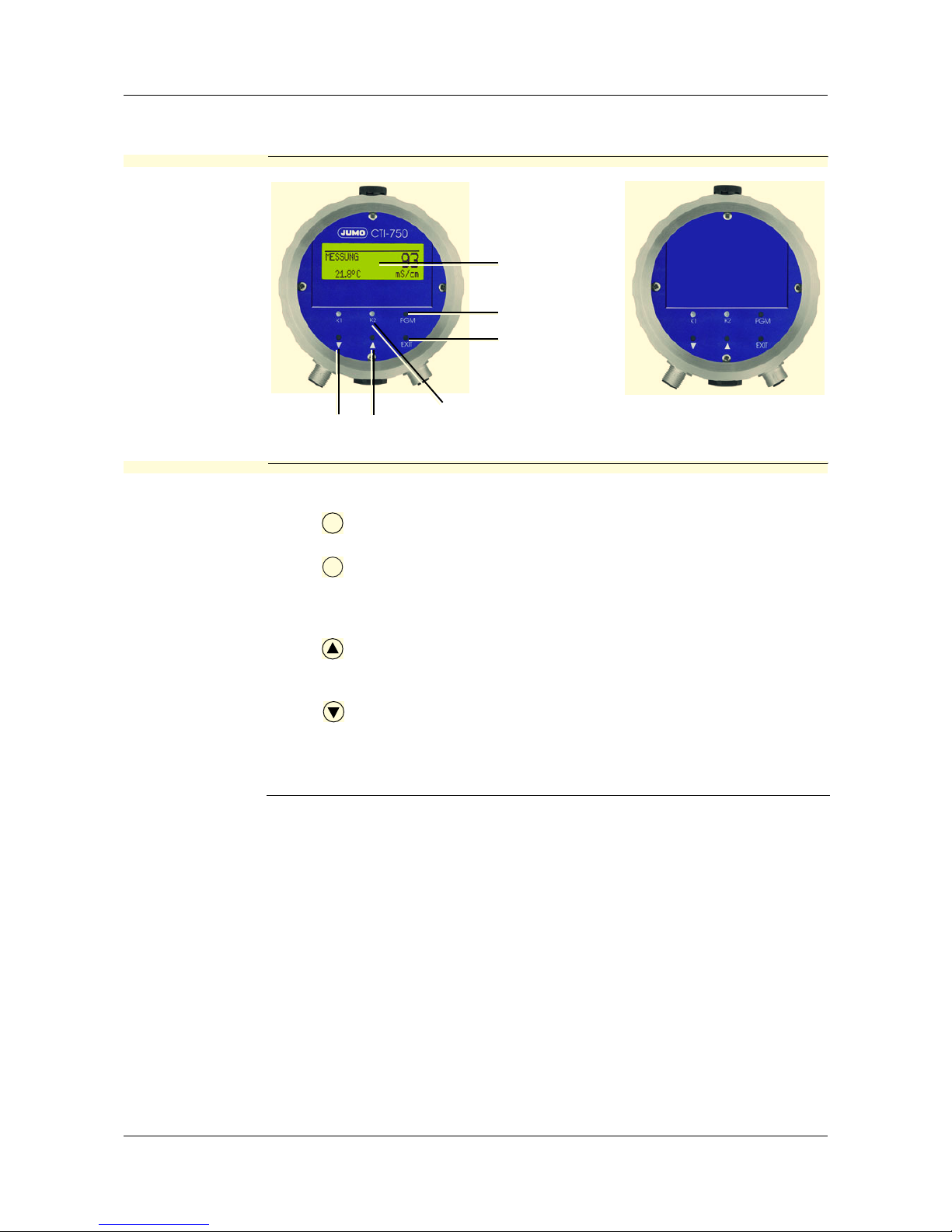
10.1 Operating elements
JUMO CTI-750
with and without
LC-Display
(1) Graphical LC-display,
background lit up.
(2) Key
confirm inputs, select menu.
(3) Key
interrupt inputs without saving /
interrupt calibration.
One menu-level back.
(4) Key
increase numerical value /
forward the selection.
(5) Key
decrease numerical value /
forward the selection.
(1)
(2)
(3)
(4)
(5)
(5)
PGM
EXIT
(6) LEDs "K1" / "K2" indicate the
status of the switching outputs.
In normal operation, the LED
flows when the corresponding
switching output is active.
If the wiper function is activated, the LED only indicates
the status.
The LED "K1" flashes during the
calibration.
In case of an error, LEDs "K1" and
LED "K2".flash.
Page 37

37
10 Operation
LC-Display
(1)
(2)
(3)
(4)
(5)
(6)
Output K1 is active
Output K2 is active
Binary input 1 is
triggered
Binary input 2 is
triggered
Keyboard is locked
Device status (hints)
- Alarm (e.g. overrange)
- Calib. flashing (calibration
timer
run out)
- Calib (customer calibration
enabled)
(7)
(8)
(9)
(10)
(11)
Output mode
- manual (manual operation)
- hold (hold operation)
Conductivity /concentration-
measured value
Unit of the conductivity- /con-
centrations measured value
Medium temperature
Device status e.g.
- Measurement (normal)
- Desalination (desalination
function)
- Dosing (desalination function)
- Locked (desalination function)
- Status of the calibration
(1) (2) (3) (4) (6)(5) (7)
(8)
(9)(10)
(11)
Page 38

10 Operation
38
10.2 Operation principle
10.2.1 Operating in levels
Measurement mode, see chapter 10.4 "Measurement mode", page 41
OPERATOR LEVEL, see chapter 10.5 "Operating level", page 41
INPUT CONDUCTIVITY MEASUREMENT RANGE 1...4
TEMP.COMPENSATION
TEMP.COEFFICIENT 1...4
REFERENCE TEMPERATURE
REL.CELL CONSTANT
MOUNTING FACTOR
CONCENTR.MEASUREMENT
CONCENTR.RANGE
OFFSET
FILTER TIME
CALIBR.INTERVAL
OUTPUT CONDUCTIVITY SIGNAL TYPE
SCALING START 1...4
SCALING END 1...4
IN CASE OF ALARM
IN CASE OF CALIBRATION
SAFETY VALUE
MANUAL OPERATION
MANUAL VALUE
INFLOW TEMPERATURE UNIT
MEASURED VALUE ACQUISITION
MANUAL SPEC.
OFFSET
FILTERING TIME
OUTFLOW TEMPERATURE SIGNAL TYPE
SCALING START
SCALING END
IN CASE OF ALARM
AT TIME O F C A L I B R AT I O N
SAFETY VALUE
MANUAL OPERATION
MANUAL VALUE
OUTPUT BINARY 1 FUNCTION
LIMIT VALUE
HYSTERESIS
DISTANCE
MANUAL OPERATION
IN CASE OF HOLD
IN CASE OF ALARM / CALIB.
SWITCH-ON DELAY
SWITCH-OFF DELAY
PULSE DURATION
OUTPUT BINARY 2 FUNCTION
LIMIT VALUE
HYSTERESIS
DISTANCE
MANUAL OPERATION
IN CASE OF HOLD
IN CASE OF ALARM / CALIB.
SWITCH-ON DELAY
SWITCH-OFF DELAY
PULSE DURATION
INPUT BINARY 1 FUNCTION
INPUT BINARY 2 FUNCTION
DESALINATION FUNCTION REDUCTION
DOSING TIME
LOCKING TIME
Page 39

10 Operation
39
DEVICE DATA LANGUAGE
CONTRAST
LIGHTING
LCD INVERSE
ADMINISTR.-LEVEL, see chapter 10.6 "Administrator level", page 49
Password
PAR AMET ER-L EVEL
, see chapter 10.6.1 "Parameter level", page 50
INPUT CONDUCTIVITY.
OUTPUT CONDUCTIVITY
INPUT TEMPERATURE
OUTPUT TEMPERATURE
OUTPUT BINARY 1
OUTPUT BINARY 2
INPUT BINARY 1
INPUT BINARY 2
DESALINATION FUNCTION
DEVICE DATA
ENABLE LEVEL
, see chapter 10.6.2 "Release level", page 50
INPUT CONDUCTIVITY.
OUTPUT CONDUCTIVITY
INPUT TEMPERATURE
OUTPUT TEMPERATURE
OUTPUT BINARY 1
OUTPUT BINARY 2
INPUT BINARY 1
INPUT BINARY 2
DESALINATION FUNCTION
DEVICE DATA
CALIB ENABLE
, see chapter 10.6.3 "Calibration release (CALIB.RELEASE)", page 50
REL. CELL CONST.
TEMP. COEFF.. LINEAR
TEMP. COEFF. N-LINEAR
CALIBR.-LEVEL
, see chapter 10.7 "Calibration level", page 51
REL. CELL CONST.
TEMP. COEFF.. LINEAR
TEMP. COEFF. N-LINEAR
DESALINATION FUNCTION
, see chapter 10.8 "The desalination function", page 52
REDUCTION
DOSING TIME
LOCKING TIME
Page 40

10 Operation
40
10.3 Principle
Level
Page 41

41
10 Operation
10.4 Measurement mode
Depiction In the measurement mode, the conductivity compensated to the reference
temperature, or the concentration, and the temperature of the measurement
medium are displayed.
10.5 Operating level
In this level, all the parameters that have been released by the Administrator
(Administrator level) can be edited. All the other parameters (marked by a key
) can only be read.
✱ Press the key for longer than 3 seconds.
✱ Select "OPERATOR LEVEL".
(1) MEASUREMENT -> Measurement mode
(2) 20.5°C -> Temperature of the measurement medium
(3) 203 mS/cm -> compensated conductivity of the measurement medium
(referred to the reference temperature, generally 25°C).
PGM
(1)
(2)
(3)
Page 42

10 Operation
42
10.5.1 INPUT CONDUCTIVITY (Input conductivity)
MEASUREMENT RANGE 1...4
1
0...500 µS/cm
0...1000 µS/cm
0...2000 µS/cm
0...5000 µS/cm
0...10 mS/cm
0...20 mS/cm
0...50 mS/cm
0...100 mS/cm
0...200 mS/cm
0...500 mS/cm
0...1000 mS/cm
0...2000 mS/cm UNK
2
1
The measurement ranges 2, 3 and 4 are only used if
"INPUT BINARY" is configured on "MEASUREMENT RANGE./TEMP C.".
2
This measurement range is not temperature-compensated.
TEMP. COMPENSATION
LINEAR
NON-LINEAR (see "Non-linear temperature coefficient (ALPHA)", page 60)
NAT WATERS (permissible temperature range 0...36°C according to EN 27
888)
TEMP. COEFFICIENT 1...4
1
0...2.20...5.5%
1
The ranges 2, 3 and 4 are only used if
"INPUT BINARY" is configured on "MEASUREMENT RANGE./TEMP C.".
REFERENCE TEMPERATURE
15.0...25.0...30°C
CELL CONSTANT
2.00...6.80...10.0 1/cm
Checking or changing is only necessary if there is a substitute sensor (base
type supplementation 85) connected to the transmitter with a separate sensor.
The cell constant is printed on the substitute sensor (K=x,xx).
REL. CELL CONSTANT
80.0...100.0...120%
Page 43

43
10 Operation
MOUNTING FACTOR
80.0...100.0...120%
If the minimum distances (20 mm) of the sensor to the outer wall cannot be
maintained, a limited compensation can be achieved with this parameter.
CONCENTR. MEASUREMENT
NO FUNCT.
NaOH
HNO3
CUST. SPEC. (The input of the values is only possible with the optional
Setup program)
CONCENTR.
RANGE
In case of HNO
3
0...25 % by WEIGHT
36...82 % by WEIGHT
In case of NaOH
0...15 % by WEIGHT
25...50 % by WEIGHT
OFFSET
-100...0...+100 mS/cm (+/- 10% of the measurement range)
FILTERING TIME
00:00:00...00:00:01...00:00:25 H:M:S
CALIBR.-INTERVAL
0...999 DAYS (0 = switched off)
Page 44

10 Operation
44
10.5.2 OUTPUT CONDUCTIVITY. (Output conductivity)
SIGNAL TYPE
0...20 mA
4...20 mA
20...0 mA
20...4 mA
0...10 V
2...10 V
10...0 V
10...2 V
SCALING START 1...4
1
0 µS/cm = 4 mA
Can be set in the current measurement range, depending on the signal type
1
The ranges 2, 3 and 4 are only used if
"INPUT BINARY" is configured on "MEASUREMENT RANGE./TEMP C.".
SCALING END 1...4
1
1000 µS/cm = 20 mA
Can be set in the current measurement range, depending on the signal type
1
The ranges 2, 3 and 4 are only used if
"INPUT BINARY" is configured on "MEASUREMENT RANGE./TEMP C.".
IN CASE OF
ALARM
LOW (0 mA / 0 V / 3,4 mA / 1,4 V)
HIGH (22 mA / 10.7 V)
SAFETY VALUE (depending on the signal type)
AT THE TIME OF CALIBRATION
ACCOMPANYING
FROZEN
SAFETY VALUE
SAFETY VALUE
0,0...4,0...22,0 mA (depending on the signal type)
0...10,7 V
MANUAL OPERATION
off
on
MANUAL VALUE
0,0...4,0...22,0 mA (depending on the signal type)
0...10,7 V
Page 45

45
10 Operation
10.5.3 INFLOW TEMPERATURE
UNIT
°C
°F
MEASUREMENT VALUE ACQUISITION
Sensor
manual
MANUAL SPECIFICATION
-20.0...25.0...150.0°C
OFFSET
-15.0...0.0...+15.0°C
FILTERING TIME
00:00:00...00:00:01...00:00:25 H:M:S
10.5.4 OUTFLOW TEMPERATURE
SIGNAL TYPE
0...20 mA
4...20 mA
20...0 mA
20...4 mA
0...10 V
2...10 V
10...0 V
10...2 V
SCALING START
-20 ... 0.0°C = 4 mA (depending on the signal type)
SCALING END
+200 ... 150.0°C = 20 mA (depending on the signal type)
IN CASE OF ALARM
LOW (0 mA / 0 V / 3,4 mA / 1,4 V)
HIGH (22 mA / 10.7 V)
SAFETY VALUE (depending on the signal type)
Page 46

10 Operation
46
AT THE TIME OF CALIBRATION
ACCOMPANYING
FROZEN
SAFETY VALUE
SAFETY VALUE
0,0...4,0...22,0 mA (depending on the signal type)
0...10,7 V
MANUAL OPERATION
off
on
MANUAL VALUE
0,0...4,0...22,0 mA (depending on the signal type)
0...10,7 V
10.5.5 OUTPUT BINARY 1 and OUTPUT BINARY 2
FUNCTION
NO FUNCTION
COND. MIN.
COND. MAX.
COND. LK1
COND. LK2
TEMP. MIN.
TEMP. MAX.
TEMP. LK1
TEMP. LK2
CALIBR. TIMER
ALARM
Max limit comparator Min limit comparator
Hysteresis
Cond.
On
Off
Limit value
Setpoint
Hysteresis
Limit value
Setpoint
Cond.
On
Off
Page 47

47
10 Operation
LIMIT VALUE
-20.0... 999.0 (depending on the function, see above)
HYSTERESIS
0.0...1.0...999.0 (depending on the function, see above)
DISTANCE
0.0... 999.0 (depending on the function, see above)
MANUAL OPERATION
OFF
ON
IN CASE OF HOLD
INACTIVE
ACTIVE
FROZEN
IN CASE OF ALARM / CALIB.
INACTIVE
ACTIVE
FROZEN
Alarm window LK1 Alarm window LK2
Wiper contact
Triggering condition longer than
pulse duration
Wiper contact
Triggering condition shorter than
pulse duration
Hysteresis
Cond.
On
Off
Limit value
Setpoint
Distance
Hysterese
Sollwert
Lf
Ein
Aus
Grenzwert
Abstand
Page 48

10 Operation
48
SWITCH-ON DELAY
00:00:00...01:00:00 H:M:S
SWITCH-OFF DELAY
00:00:00...01:00:00 H:M:S
PULSE DURATION
00:00:00...01:00:00 H:M:S (see above: "Function, wiping contact)
10.5.6 INPUT BINARY 1 and INPUT BINARY 2
FUNCTION
NO FUNCTION
KEYBOARD LOCK/HOLD
MEASUREMENT RANGE./TEMP C.
DESALINATION FUNCTION.
10.5.7 DESALINATION FUNCTION (Description see "The desalination function", page
52)
REDUCTION
0...10...50%
DOSING TIME
0:00:00...00:01:00...18:00:00 H:M:S
LOCKING TIME
0:00:00...00:01:00...18:00:00 H:M:S
Setting parameters binary input 1 binary input 2
Measurement range- /
Temperaturecoefficient
switching
MB1 / Tk1 open open
MB2 / Tk2 closed open
MB3 / Tk3 open closed
MB4 / Tk4 closed closed
Keyboard lock closed X
Hold-function X closed
Desalination function: Start close (flank 0 - 1) open
Desalination function Stop open close (flank 0 - 1)
Page 49

49
10 Operation
10.5.8 DEVICE DATA
LANGUAGE
GERMAN
ENGLISH
FRENCH
SPANISH
POLISH
SWEDISH
ITALIAN
PORTUGUESE
DUTCH
RUSSIAN
CONTRAST
0...6...11
LIGHTING
OFF
ON
FOR OPERATION (about 50 s after the last keystroke,
the lighting gets switched off)
INVERSE LCD
OFF
ON
10.6 Administrator level
- All the parameters can be edited in this level.
- In this level, it is also possible to determine which parameters a "normal"
user may edit or which calibrations may be carried out.
Editable parameters can be edited in the operator level.
Non-editable parameters are marked in the operator level with a key symbol .
You can get to the Administrator level as follows:
✱ Press the key for longer than 3 seconds.
✱ With the keys or , select "ADMINISTRATOR-LEVEL".
✱ Keys or input the password 300.
✱ Press the key .
By inputting the password 7485 in the Administrator level, the
operating language is reset to English.
PGM
PGM
Page 50

10 Operation
50
Levels of the
Administrator
level
10.6.1 Parameter level
In this level, the Administrator can edit any parameter of the operator level.
The structure of the parameter level in the Administrator level is identical to the
operator level
see "Operating level", page 41 and onwards.
10.6.2 Release level
In this level, the Administrator can determine which parameters the operator is
permitted to modify in the operator level..
The options "READ ONLY" and "EDIT" are available for the purpose.
The structure of the parameter level in the Administrator level is identical to the
operator level
see "Operating level", page 41 and onwards.
10.6.3 Calibration release (CALIB.-RELEASE)
In this level, the Administrator can specify whether the operator may calibrate
- the relative cell constant
- the linear temperature coefficient
- the non-linear temperature coefficient
Page 51

51
10 Operation
i.e. change them
10.7 Calibration level
In this level, the calibrations released by the Administrator (Administrator level)
can be carried out.
✱ Press the key for longer than 3 seconds.
✱ With the keys or , select "CALIBRATION-LEVEL".
10.7.1 REL. CELL CONSTANT. (relative cell constant)
If this function has been released by the Administrator, the operator can calibrate the relative cell constant of the JUMO CTI-750 here;
see "Calibration of the relative cell constant", page 56.
10.7.2 TEMP. COEF. LINEAR (Temperature coefficient linear)
If this function has been released by the Administrator, the operator can calibrate the JUMO CTI-750 on fluids with linear temperature coefficients;
see "Linear temperature coefficient (ALPHA)", page 57.
10.7.3 TEMP. CO. N-LINEAR (Temperature coefficient, non-linear)
If this function has been released by the Administrator, the operator can calibrate the JUMO CTI-750 on fluids with non-linear temperature coefficients;
see "Non-linear temperature coefficient (ALPHA)", page 60.
PGM
Page 52

10 Operation
52
10.8 The desalination function
Brief description
In the case of cooling water, using the conductivity, the total salt content is
assessed. Upon reaching a limiting conductivity (at maximum permissible salt
concentration / densification), dilution of the cooling water is necessary. For
this purpose, a desalination valve is opened, densified water flows out and is
supplemented with fresh water. After the conductivity of the cooling water has
dropped below the limit value, the desalination valve is closed again.
Addition of biocide
In order to prevent biological growth in cooling systems, biocides are added to
the cooling water. There is no ideal control variable for the added quantity and
time of a biocide dosing. In most cases, the dosing time is used as the control
variable. Here, the dosing quantity is obtained from the pump capacity and
pump operating time (plant-specific). The success of the biocide treatment
must be checked at regular intervals.
Desalination
before the addition of biocide
If a conductivity-enhancing biocide is added to the cooling water, the conductivity can cross the limit value as a result. Thereupon, the desalination valve
would open and a part of the added biocide would be discharged into the
effluent canal (note and comply with the legal conditions!).
To prevent this, before adding the biocide, the conductivity in the cooling system is reduced by desalination by about 10% below the limit value. Thereafter,
the desalination valve is temporarily blocked.
Desalination
locking
After the addition of the biocide, the desalination should be blocked till the
biocide that has been added has mostly decomposed in the cooling system
(not and comply with the legal requirements.).
Realization in
the case of the
JUMO CTI-750
- The desalination function is only possible in the mode "Conductivity measurement". Not in the case of concentration measurement..
- If the desalination function is activated, all the parameters that are not relevant for this function are turned off.
- The desalination function can be started via the binary input 1 and stopped
using the binary input 2, see "INPUT BINARY 1 and INPUT BINARY 2",
page 48.
The desalination function can also be stopped with the key.
- The current status of the desalination function is shown in the display.
- The desalination valve is controlled through output K1.
- The addition of biocide is controlled via output K2.
- After the desalination, K1 goes into the configured Hold state (desalination
locking).
EXIT
Page 53

53
10 Operation
- The desalination reduction can be set in the range from 1...50% below the
actual limit value of binary input 1. The default setting is 10% below the
limit value.
10.8.1 Setting the desalination function
All the parameters are plant-dependent and must be matched to the prevalent
conditions.
✱ Press the key for longer than 3 seconds.
✱ With the keys or , select the "OPERATOR LEVEL"; with key , con-
firm the selection.
✱ With the keys or , select "INPUT BINARY"; with key , confirm the
selection.
PGM
PGM
PGM
Page 54

10 Operation
54
✱ With the keys or , select "DESALINATION FUNCT.". with key ,
confirm the selection.
✱ Use the key to switch to the operator level.
✱ With the key select "DESALINATION FUNCTION".
✱ With key , confirm the selection.
✱ Set the desalination reduction with the keys or in the range from
1...10...50% below the actual limit value.
✱ with key , confirm the setting.
✱ With the keys or , select "DOSING TIME"; with key , confirm the
selection.
✱ Set the dosing time with the keys or in the range from
0:00:00...00:01:00...18:00:00 H:M:S.
✱ with key , confirm the setting.
PGM
EXIT
PGM
PGM
PGM
PGM
Page 55

55
10 Operation
✱ With the keys or , select "LOCKING TIME"; with key , confirm the
selection.
✱ Set the locking time with the keys or in the range from
0:00:00...00:01:00...18:00:00 H:M:S.
✱ with key , confirm the setting.
If there is a failure of the supply voltage during the running of the
desalination function, the function is canceled.
In order that the desalination function can run again, it must be
started again.
PGM
PGM
Page 56

56
11 Calibration
11.1 General
For increasing the accuracy, the device has various calibration options.
11.2 Calibration of the relative cell constant
In case of increased demands on the accuracy, the cell constant must first be
calibrated.
Precondition - the JUMO CTI-750 must be supplied with power.
see chapter 7 "Installation", page 30ff.
- The sensor must be connected to the transmitter (in case of "shouldered"
construction).
- The transmitter is in "Measurement mode".
✱ Submerge the conductivity sensor in a reference solution of known conduc-
tivity.
✱ Press the key for longer than 3 seconds.
✱ With the keys or , select "CALIBRATION-LEVEL". With key , con-
firm the selection.
At regular intervals (depending on the measurement medium), the
conductivity sensor must be cleaned and calibrated.
The LED "K1" flashes during the calibration.
During the calibration, the temperature of the measurement solution must remain constant.
PGM
PGM
Page 57

57
11 Calibration
✱ With the keys or , select "REL. CELL CONSTANT.". with key ,
confirm the selection.
✱ When the measured value is stable, press the key.
✱ With the keys or , correct the displayed uncompensated conductiv-
ity value to the conductivity value of the reference solution.
✱ Press the key.
The relative cell constant calculated by the JUMO CTI-750 is displayed.
✱ Accept the relative cell constant determined -> press the key for longer
than 3 seconds, or
discard the value -> press the key .
The transmitter is in the "Calibration menu".
✱ Press key ;
The transmitter is in "Measurement mode" and displays the compensated
conductivity of the reference solution.
11.3 Calibration of the temperature coefficient of the measurement solution
11.3.1 Linear temperature coefficient (ALPHA)
The conductivity of any measurement solution changes according it its specific temperature coefficient.
We therefore recommend carrying out the calibration of the temperature coefficient
PGM
PGM
PGM
PGM
EXIT
EXIT
Page 58

11 Calibration
58
Precondition - the JUMO CTI-750 must be supplied with power.
see chapter 7 "Installation", page 30ff.
- The sensor must be connected to the transmitter (in case of "shouldered"
construction).
- The transmitter is in "Measurement mode".
✱ Submerge the conductivity sensor in a sample of the measurement solu-
tion.
✱ Press the key for longer than 3 seconds.
✱ With the keys or , select "CALIBRATION-LEVEL". with key , con-
firm the selection.
✱ With the keys or , select "TEMP. COEFF LINEAR". with key , con-
firm the selection.
✱ With the keys or , input the operating temperature and confirm with
the key .
The operating temperature must be at least 5°C above or below
the reference temperature (25.0°C).
PGM
PGM
PGM
PGM
Page 59

59
11 Calibration
The LC-Display now shows
- at the top (1) the selected operating temperature (flashing)
- below that (2) the reference temperature (flashing)
- below that (3) the current sensor temperature (static)
✱ Heat the measurement medium till both the reference temperature as well
as the operating temperature are reached (the corresponding value does
not flash any more).
The LC-display now shows the determined temperature coefficient in %/K.
Accept the temperature coefficient determined -> press the key for longer
than 3 seconds, or
discard the value -> press the key .
The transmitter is in the "Calibration menu".
✱ Press key ;
The transmitter is in "Measurement mode" and displays the compensated
conductivity of the reference solution.
During the calibration, the temperature changing speed of the
measurement solution of
10 K/min in the case of JUMO CTI-750 with a free-standing temperature sensor or
1 K/min in the case of JUMO CTI-750 with an integrated temperature sensor
must not be exceeded.
As soon as one of the target temperatures is reached, its display
becomes static (not flashing).
Calibration is also possible in the cooling process (under dropping
temperature). The start is made above the operating temperature,
the end below the reference temperature.
PGM
EXIT
EXIT
(1)
(2)
(3)
Page 60

11 Calibration
60
11.3.2 Non-linear temperature coefficient (ALPHA)
General Since the temperature coefficient of some media is not constant over a larger
temperature range, the JUMO CTI-750 has the facility to divide a temperature
range (T
start
to T
end
) into 5 sub-ranges. In each of these ranges, compensation
can be carried out with different TC values. This so-called TC curve can
- be edited with the Setup program and transmitted to the device
- or calibrated automatically at the device.
Determining the
TC-curve
Calculation of a
temperature
coefficient
α = Temperature coefficient (TC)
γ = uncompensated conductivity
γ
Ref
T=T
Start 1
Temperature
Uncompensated
conductivity
γ
2
T
2
T
Ref
T=T
End 6
T
5
T
3
T
4
1
2
3
4
5
Page 61

61
11 Calibration
TC-curve
Temperature
compensation
with the TCcurve
With the help of the current medium temperature, the corresponding temperature coefficient is determined from the TC curve,’
see "TC-curve", page 61.
Intermediate values, e.g. (α
x
in the case of Tx) between two determined values
(α
3
in the case of T3) and (α4 in the case of T4) are approximated linearly.
With the TC determined, the compensated electric conductance is calculated
as in the case of the linear temperature compensation.
Sequence of the
automatic
calibration on
the JUMO CTI750
The TC curve is plotted automatically in a temperature range determined by
the user. Here, the temperature range from the starting to the final temperature
is divided into 5 equal sections.
The temperature range must be greater than 20 Kelvin and overlap the reference temperature.
Example: Reference temperature 25°C, starting temperature 18°C and final
temperature 50°C.
If the measured temperature is less than the starting temperature,
compensation is done with the first TC.
If the measured temperature is greater than the final temperature,
compensation is done with the last TC.
Page 62

11 Calibration
62
Precondition - the JUMO CTI-750 must be supplied with power.
see chapter 7 "Installation", page 30ff.
- The sensor must be connected to the transmitter (in case of "shouldered"
construction).
- The transmitter is in "Measurement mode".
✱ Submerge the conductivity sensor in a sample of the measurement solu-
tion.
✱ Press the key for longer than 3 seconds.
✱ With the keys or , select "CALIBRATION-LEVEL". with key , con-
firm the selection.
✱ With the keys or , select "TEMPCO. N-LINEAR". with key , con-
firm the selection.
The temperature changing speed may not exceed
- 10 K/min in case of a free-standing temperature sensor and
- 01 K/min in case of an integrated temperature sensor
!
PGM
PGM
PGM
Page 63

63
11 Calibration
✱ With the keys or , input the starting temperature and confirm with
the key .
✱ With the keys or , input the final temperature and confirm with the
key .
The transmitter automatically determines the temperature data points. The LC
display now shows
- at the top (1) the next temperature to be reached (flashing)
- below that (2), the current sensor temperature (static)
✱ Heat the measurement medium till the flashing temperature is exceeded or
undershot.
The starting temperature must be below the reference temperature
(25.0°C).
The final temperature must be at least 20°C above the starting
temperature.
PGM
PGM
(1)
(2)
Page 64

11 Calibration
64
The next temperature to be reached is displayed flashing.
✱ Heat the measurement medium till the flashing temperature is exceeded.
✱ Repeat the procedure till all 6 temperature coefficients are determined by
the JUMO CTI-750.
The LC-display now shows the determined temperature coefficients in %/K.
✱ Accept the temperature coefficients determined -> press the key for
longer than 3 seconds, or
discard the values -> press the key .
The transmitter is in the "Calibration menu".
✱ Press key ;
The transmitter is in "Measurement mode" and displays the compensated
conductivity of the reference solution.
During the calibration, the temperature changing speed of the
measurement solution of
10 K/min in the case of JUMO CTI-750 with a free-standing temperature sensor or
1 K/min in the case of JUMO CTI-750 with an integrated temperature sensor
must not be exceeded.
As soon as one of the target temperatures is reached, its display
becomes static (not flashing).
PGM
EXIT
EXIT
Page 65

65
12 Maintenance
12.1 Conductivity-clean sensor
Deposits Deposits on the sensor part can be removed with a soft brush (e.g. bottle
brush).
Do not use any solvents.
Stubborn sediments or deposits can be dissolved with dilute
hydrochloric acid and removed.
Comply with the safety specifications.
Page 66

66
13 Rectifying errors and faults
Error
possibilities
t
13.1 Device checking
General The device is calibrated at the factory and is maintenance-free. If measure-
ment value variations from unknown causes should occur nonetheless, the
transmitter can be checked as follows.
Problem Possible cause Measure
No display of measured
value
or
signal output
Voltage supply absent Check voltage supply,
check terminals
Measured value display
000 or
signal output 0%
(e.g. 4 mA)
Sensor not submerged in
medium;
Tank level too low
Fill up tank
Flow meter
blocked
Clean the flow meter
Sensor faulty see "Device checking",
page 66
Measured value display
8888 flashing +
device status ALARM
flashing.
The temperature display
is OK
or
LED 1 + LED 2
flashing
Out of range => the measurement/ display range
was exceeded or undershot
select suitable measurement range or check the
concentration table
Measured value display
8888 flashing +
device status ALARM
flashing.
The temperature display
is 8888 flashing
or
LED 1 + LED 2
flashing
The temperature sensor
is faulty
The transmitter or the
conductivity sensor must
be replaced.
or
set measured value ac-
quisition "Inflow temperature" briefly to manual,
see "INFLOW TEMPERATURE" , page 45.
wrong or varying
measured value display
Sensor not submerged
deep enough
Fill the tank
no blending taking place ensure good blending
near the sensor, ensure
clearance of
about 5 mm for
circulation
Air bubbles Check installation loca-
tion,
see "General", page 21.
Page 67

67
13 Rectifying errors and faults
13.1.1 Checking with resistance loop
Position of the
resistance loop
✱ Lead a wire through the measurement cell (see Figure)
✱ Connect the resistance R to the wire
Calculation of
the
resistance
Formula for calculation of the resistance of the resistance loop:
Remark: 1 mS/cm = 1·10
-3
S/cm
1 µS/cm = 1·10
-6
S/cm
In case of display values up to 20 mS, the resistance loop must have 1 turn.
In case of display values from 50 mS onwards, the resistance loop must have
3 turns.
When calibrating the sensitive part of the measurement cell, do not
place on or touch any surface, else the measured value will get falsified.
R =
N
2
· K
R = Resistance of the resistance loop
Lf N = Number of turns in the loop
K = Cell constant
Lf = desired display in S/cm
The cell constant of the JUMO CTI-750 depends on the structural
shape.!
The Tee measuring cell has a cell constant of 6.80 1/cm.
The VARIVENT
®
-measuring celll has a cell constant of 6.50 1/cm.
Page 68

13 Rectifying errors and faults
68
Example 1 The JUMO CTI-750 with Tee-shaped measuring cell should display 20 mS:
To get a display of 20 mS/cm, the resistance loop (with 1 turn) must have a resistance of 340 Ohm.
Example 2 The JUMO CTI-750 with Tee-shaped measuring cell should display 500 mS:
To get a display of 500 mS/cm, the resistance loop (with 3 turns) must have a
resistance of 122.4 Ohm.
R =
1
2
·6.80 1/cm
= 340
Ω
20·10-3 S/cm
R =
3
2
·6.80 1/cm
= 122.4
Ω
500·10-3 S/cm
Page 69

69
13 Rectifying errors and faults
Pre-calculated
values
The display value 0 is obtained when the sensor is dry and without conducting
coats, as well as when there is no resistance loop.
Structural shape/ Cell constant
Material: PEEK
K = 6.80 1/cm
Material: PEEK
K = 6.50 1/cm
Display in case of
measurement
range end
Number of
turns
Cell constant
[1/cm]
Required resis-
tance
[Ω]
500 µS/cm 1 6,80 13600,00
1 6,50 13000,00
1000 µS/cm 1 6,80 6800,00
1 6,50 6500,00
2000 µS/cm 1 6,80 3400,00
1 6,50 3250,00
5000 µS/cm 1 6,80 1360,00
1 6,50 1300,00
10 mS/cm 1 6,80 680,00
1 6,50 650,00
20 mS/cm 1 6,80 340,00
1 6,50 325,00
50 mS/cm 3 6,80 1224,00
3 6,50 1170,00
100 mS/cm 3 6,80 612,00
3 6,50 585,00
200 mS/cm 3 6,80 306,00
3 6,50 292,50
500 mS/cm 3 6,80 122,40
3 6,50 117,00
1000 mS/cm 3 6,80 61,20
3 6,50 58,50
2000 mS/cm 3 6,80 30,60
3 6,50 29,25
Material: PVDF
K = 5.45 1/cm
Page 70

13 Rectifying errors and faults
70
Carry out test ✱ Determine test resistance.
✱ Connect the JUMO CTI-750 electrically, see chapter 7 "Installation", page
30.
✱ Select the corresponding measurement range, see chapter 10.5.1 "INPUT
CONDUCTIVITY (Input conductivity)", page 42 -> MEASUREMENT RANGE
1...4
✱ Set TC to 0%/K, see chapter 10.5.1 "INPUT CONDUCTIVITY (Input con-
ductivity)", page 42 -> TEMP.COEFFICIENT.
✱ Put the resistance loop in place in accordance with the figure.
13.1.2 Testing with reference fluid
Put in test solution
Carry out test ✱ Prepare the conductivity test solution in a sufficiently large container
✱ Connect the device electrically, see chapter 7 "Installation", page 30.
✱ Select the measurement range according to the conductivity test solution,
see chapter 10.5.1 "INPUT CONDUCTIVITY (Input conductivity)", page 42 > MEASUREMENT RANGE 1...4
✱ Set TC to 0%/K, see chapter 10.5.1 "INPUT CONDUCTIVITY (Input con-
ductivity)", page 42 -> TEMP.COEFFICIENT.
✱ Submerge the measurement cell in the container and do not move any
more during the measurement.
Page 71

71
13 Rectifying errors and faults
13.1.3 Testing with reference measuring instrument
Put in test solution
Carry out test ✱ Prepare the conductivity test solution in a sufficiently large container
✱ Connect the JUMO CTI-750 electrically, see chapter 7 "Installation", page
30.
✱ Select the measurement range according to the conductivity test solution,
see chapter 10.5.1 "INPUT CONDUCTIVITY (Input conductivity)", page 42 > MEASUREMENT RANGE 1...4
✱ Set TC to 0%/K, see chapter 10.5.1 "INPUT CONDUCTIVITY (Input con-
ductivity)", page 42 -> TEMP.COEFFICIENT.
✱ Set the TC of the reference instrument also to 0%/K (see operating manual
of the reference instrument). If that is not possible, the liquid sample must
be tempered to the reference temperature of the reference instrument.
✱ Submerge the measuring cell to be tested and the measuring cell of the ref-
erence instrument in the tank and do not move them any more at all during
measurement.
✱ The output and the display of the instrument to be tested or the display of
the display device connected to it and that of the reference device connected to it must match after taking the permissible instrument errors into
account.
Page 72
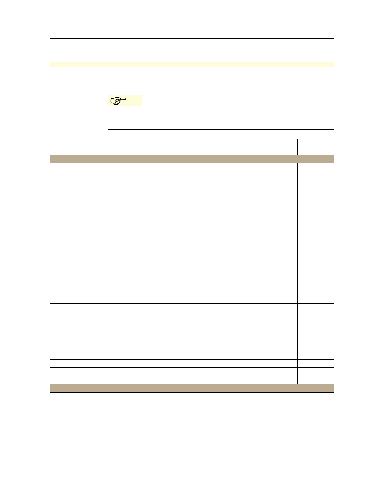
72
14 Annex
14.1 Before configuring
If many parameters of the device are to be re-configured, it is advisable to
make a note of all the parameters to be changed in the following table, and to
process the parameters in the given sequence.
The following list shows the maximum number of modifiable
parameters.
Depending on the configuration, some of the parameters are not
modifiable (editable) in this device.
Parameter Selection / Range of values
Factory setting
New setting see page
Input, conductivity
Measurement range 1...4 0...500 µS/cm
0...1000 µS/cm
0...2000 µS/cm
0...5000 µS/cm
0...10 mS/cm
0...20 mS/cm
0...50 mS/cm
0...100 mS/cm
0...200 mS/cm
0...500 mS/cm
0...1000 mS/cm
0...2000 mS/cm (uncompensated)
42
Temperature compensation
linear
non-linear
natural water
42
Temperature coefficient
1...4
0...2.20...5.5%/K 42
Reference temperature 15.0...25.0...30°C 42
Cell constant 2.00...6.80...10.00 1/cm 42
Relative cell constant 80.0...100.0...120.0% 42
Mounting factor 80,0...100.0...120,0% 43
Concentration measure-
ment
no function
NaOH
HNO
3
customer-specific
43
Offset -200...0...+200 mS/cm 43
Filtering time 00:00:01...00:00:25 H:M:S 43
Calibration interval 0...999 days 43
Output, conductivity
Page 73

73
14 Annex
Signal type 0...20 mA
4...20 mA
20...0 mA
20...4 mA
0...10 V
2...10 V
10...0 V
10...2 V
44
Scaling, beginning 0...90% = 4 mA (e.g.)
from the measurement range scope
44
Scaling: End 100...10% = 20 mA (e.g.)
from measurement range scope
44
In case of an alarm low
high
safety value
44
At the time of calibration accompanying
frozen
safety value
44
Safety value 0.0...4.0...22.0 mA 44
Manual operation off
on
44
Manual value 0.0...4.0...22.0 mA 44
Inflow temperature
Unit °C
°F
45
Measurement value acquisition
Sensor
manual
45
Manual specification -20.0...25...150°C 45
Offset -15.0...0.0...+15°C 45
Filtering time 00:00:00...00:00:01...00:00:25 H:M:S 45
Outflow temperature
Signal type 0...20 mA
4...20 mA
20...0 mA
20...4 mA
0...10 V
2...10 V
10...0 V
10...2 V
45
Scaling, beginning -20...0.0...183°C = 4 mA
(0...90% of measurement range
scope)
45
Parameter Selection / Range of values
Factory setting
New setting see page
Page 74

14 Annex
74
Scaling: End -3...150...200°C = 20 mA
(100...10% of measurement range
scope)
45
In case of an alarm low
high
safety value
44
At the time of calibration accompanying
frozen
safety value
44
Safety value 0.0...4.0...22.0 mA 46
Manual operation off
on
44
Manual value 0.0...4.0...22.0 mA 44
Output binary 1 or binary 2
Function no function
Conductivity min.-contact
Conductivity Max.-contact
Conductivity LK1
Conductivity LK2
Conductivity Min.-contact
Conductivity Max.-contact
Conductivity LK1
Conductivity LK2
Calibration timer
Alarm
46
Limit value 0.0...9999.0 47
Hysteresis 0.0...1.0...999.0 47
Distance 0.0...999.0 47
Manual operation off
on
47
in case of Hold inactive
active
frozen
47
in case of alarm / calibration
inactive
active
frozen
47
Switch-on delay 00:00:00...01:00:00 H:M:S 48
Switch-off delay 00:00:00...01:00:00 H:M:S 48
Pulse duration 00:00:00...01:00:00 H:M:S 48
Input binary
Parameter Selection / Range of values
Factory setting
New setting see page
Page 75

75
14 Annex
Function no function
Keyboard locking/ Hold
Measurement range / Temperature
coefficient
desalination function
48
Desalination function
Reduction 0...10...50% 48
Dosing time 00:00:00...00:01:00...18:00:00 H:M:S 48
Locking time 00:00:00...00:01:00...18:00:00 H:M:S 48
Device data
Language German
English
French
Spanish
Polish
Swedish
Italian
Portuguese
Dutch
Russian
49
Contrast 0...6...11 49
Lighting off
on
at the time of operation
49
Inverse LCD off
on
49
Parameter Selection / Range of values
Factory setting
New setting see page
Page 76

JUMO GmbH & Co. KG
Street address:
Moltkestraße 13 - 31
36039 Fulda, Germany
Delivery address:
Mackenrodtstraße 14
36039 Fulda, Germany
Postal address:
36035 Fulda, Germany
Phone: +49 661 6003-0
Fax: +49 661 6003-607
e-mail: mail@jumo.net
Internet: www.jumo.net
JUMO Instrument Co. Ltd.
JUMO House
Temple Bank, Riverway
Harlow, Essex CM20 2TT, UK
Phone: +44 1279 635533
Fax: +44 1279 635262
e-mail: sales@jumo.co.uk
Internet: www.jumo.co.uk
JUMO Process Control, Inc.
8 Technology Boulevard
Canastota, NY 13032, USA
Phone: 315-697-JUMO
1-800-554-JUMO
Fax: 315-697-5867
e-mail:
info@jumo.us
Internet: www.jumo.us
 Loading...