

Page 1

JUMO AQUIS touch P
Modular Multichannel Measuring Device for
Liquid Analysis with Integrated Controller and
Paperless Recorder
Type 202580
Operating Manual
b20.2580.0en
V2.00/EN/00607974
Page 2

Caution!
If the device or a sensor connected to it fails abruptly, it is likely that a
dangerous overdosage has occurred!
For this case, appropriate precautionary measures must be taken.
NOTE!
Read this operating manual before putting the device into service.
Keep the operating manual at a location that is readily accessible to
all users.
Page 3

Content
1 Safety information ...........................................................13
1.1 Warning symbols .............................................................................13
1.2 Indicative symbols ...........................................................................13
1.3 Intended use .................................................................................... 14
1.4 Qualification of personnel ................................................................ 14
2 Acceptance of goods, storage, and transport ..............15
2.1 Checking the delivery ......................................................................15
2.2 Important information about storage and transport .......................... 15
2.3 Returning goods ..............................................................................15
2.3.1 Accompanying letter for repair ......................................................... 15
2.3.2 Protection against electrostatic discharge (ESD) ............................ 16
2.4 Disposal ...........................................................................................16
3 Device Description ..........................................................17
3.1 Brief description ............................................................................... 17
3.2 Block diagram .................................................................................. 19
3.3 Device setup .................................................................................... 20
4 Identifying the device version ........................................21
4.1 Nameplate .......................................................................................21
4.2 Order details ....................................................................................22
5 Mounting ..........................................................................27
5.1 Notes ...............................................................................................27
5.2 Dimensions ......................................................................................28
5.3 Panel insertion ................................................................................. 30
6 Electrical connection ......................................................33
6.1 Installation notes .............................................................................. 33
6.2 Connecting cables ...........................................................................35
6.2.1 Preparing coaxial cables for pH/redox electrodes ........................... 35
6.2.2 Conductor cross-sections for base unit and power supply unit .......37
6.2.3 Conductor cross-sections for optional boards ................................. 38
6.3 Galvanic isolation ............................................................................. 39
Page 4

Content
6.4 Connection diagram ......................................................................... 40
6.4.1 Overview of connections .................................................................. 40
6.4.2 Analog inputs base unit ...................................................................42
6.4.3 Analog inputs optional boards ......................................................... 44
6.4.4 Analog outputs ................................................................................. 52
6.4.5 Binary inputs ....................................................................................53
6.4.6 Binary outputs, power supply unit board .......................................... 55
6.4.7 Binary outputs, optional boards ....................................................... 56
6.4.8 Mains power connection ..................................................................57
6.4.9 Voltage supply outputs .................................................................... 58
6.4.10 Interfaces .........................................................................................59
7 Startup ..............................................................................61
7.1 Initial startup ....................................................................................61
7.2 Function test ....................................................................................62
7.2.1 Checking the optional boards ..........................................................62
7.2.2 Checking sensors and inputs/outputs .............................................. 62
8 Operation .........................................................................65
8.1 Operating concept ...........................................................................65
8.1.1 Passwords and user rights .............................................................. 65
8.1.2 Display and control elements ...........................................................67
8.1.3 Menu structure ................................................................................. 68
8.1.4 Entry of text and numbers ................................................................ 73
8.2 Device menu .................................................................................... 75
8.2.1 Log-on/Log-out ................................................................................ 78
8.2.2 User level ......................................................................................... 79
8.2.3 Functional level ................................................................................ 80
8.2.4 Device information ........................................................................... 82
8.2.5 Service .............................................................................................83
8.2.6 Calibrating the touchscreen ............................................................. 84
8.3 Alarm/Event list ................................................................................ 85
8.3.1 Alarm list .......................................................................................... 86
Page 5

Content
8.3.2 Event list ..........................................................................................88
8.4 Memory Manager (USB flash drive) ................................................90
8.5 Operating the controllers .................................................................93
8.5.1 Automatic control mode ................................................................... 94
8.5.2 Controller in the manual mode ......................................................... 96
8.5.3 Hold mode .......................................................................................97
8.5.4 Optimizing controllers ......................................................................98
8.6 Operation of the data monitor/recording function ............................ 99
8.6.1 Data monitor/recording function control elements .........................100
8.6.2 History function .............................................................................. 103
8.7 Online visualization ........................................................................ 104
9 Parameterization ...........................................................109
9.1 Date and time ................................................................................109
9.2 Parameter Sets (Controller parameter) ......................................... 110
9.3 Setpoint values ..............................................................................113
9.4 Manual values ................................................................................ 113
10 Configuration .................................................................115
10.1 Important information ..................................................................... 115
10.2 Basic settings ................................................................................. 116
10.3 Display ...........................................................................................117
10.3.1 General Information ....................................................................... 117
10.3.2 Screen ...........................................................................................118
10.3.3 Colors ............................................................................................118
10.4 Operating loop ...............................................................................119
10.4.1 General screens ............................................................................119
10.4.2 Detailed screens ............................................................................ 120
10.5 Analog inputs ................................................................................. 121
10.5.1 Base unit temperature inputs ......................................................... 121
10.5.2 Universal inputs of base unit and optional boards ......................... 123
10.5.3 pH/Redox/NH
10.5.4 CR/Ci analysis inputs (conductive/inductive conductivity) ............. 128
analysis inputs ....................................................... 126
3
Page 6

Content
10.5.5 CR/Ci measuring ranges ...............................................................129
10.6 Analog outputs of base unit and optional boards ........................... 132
10.7 Digital inputs of base unit and optional boards .............................. 133
10.8 Digital outputs of base unit and optional boards ............................ 134
10.9 Limit monitoring and alarms ........................................................... 135
10.9.1 Limit monitoring .............................................................................135
10.9.2 Alarms for analog signals .............................................................. 135
10.9.3 Digital signal alarms ....................................................................... 138
10.10 Calibration timers ........................................................................... 139
10.10.1 Configuration of the calibration timers ........................................... 139
10.11 Controller .......................................................................................140
10.11.1 Configuration of the controllers ...................................................... 140
10.11.2 Controller inputs .............................................................................144
10.11.3 Disturbance feedforward control .................................................... 145
10.11.4 Self-optimization ............................................................................146
10.12 Setpoint value configuration ..........................................................147
10.13 Timers ............................................................................................148
10.13.1 Control timer .................................................................................. 150
10.14 Washtimer ......................................................................................151
10.15 Counters ........................................................................................152
10.16 Ethernet .........................................................................................153
10.17 Serial interfaces ............................................................................. 154
10.18 Formula ..........................................................................................154
10.19 Logic formula .................................................................................155
10.20 Manual values (configuration) ........................................................155
10.21 External analog inputs ...................................................................156
10.22 External digital inputs ..................................................................... 157
10.23 Flow ...............................................................................................157
11 Retrofitting optional boards .........................................161
11.1 Inserting optional boards ...............................................................161
11.2 Ci base calibration .........................................................................164
Page 7

Content
12 Calibration in general ...................................................169
12.1 Notes .............................................................................................169
12.2 General information .......................................................................169
12.2.1 General procedure for calibration .................................................. 169
12.3 Calibration logbook ........................................................................ 171
13 Calibrating a pH measuring chain ...............................175
13.1 Notes .............................................................................................175
13.2 General information .......................................................................175
13.2.1 Calibration methods for pH sensors ..............................................175
13.2.2 Calibration default settings for pH sensors ................................... 176
13.3 pH Calibration routines ..................................................................178
13.3.1 Zero-point calibration ..................................................................... 178
13.3.2 Two-point and Three-point calibration ........................................... 180
14 Calibrating Redox sensors ...........................................183
14.1 Notes .............................................................................................183
14.2 General information .......................................................................183
14.2.1 Calibration methods for Redox sensors ......................................... 183
14.2.2 Calibration default settings for Redox sensors .............................. 184
14.3 Redox calibration routines ............................................................. 185
14.3.1 Zero-point calibration ..................................................................... 185
14.3.2 Two-point Calibration ..................................................................... 186
15 Calibrating ammonia sensors ......................................187
15.1 Notes .............................................................................................187
15.2 General information .......................................................................187
15.2.1 Calibration methods for ammonia sensors .................................... 187
15.2.2 Calibration default settings for ammonia sensors .......................... 187
15.3 Ammonia calibration routines ........................................................188
15.3.1 Zero-point calibration ..................................................................... 188
16 Calibrating CR conductivity sensors ..........................189
16.1 Notes .............................................................................................189
Page 8

Content
16.2 General information .......................................................................189
16.2.1 Calibration methods for CR conductivity sensors (conductive) ..... 189
16.2.2 Calibration default settings for CR conductivity sensors ................ 190
16.3 CR calibration routines ..................................................................192
16.3.1 Calibrating the relative cell constant .............................................. 192
16.3.2 Calibrating the temperature coefficient .......................................... 194
17 Calibrating Ci conductivity sensors ............................197
17.1 Important information ..................................................................... 197
17.2 General information .......................................................................197
17.2.1 Calibration methods for Ci conductivity sensors (inductive) .......... 197
17.2.2 Calibration default settings for Ci conductivity sensors ................. 198
17.3 Ci calibration routines ....................................................................201
17.3.1 Calibrating the relative cell constant .............................................. 201
17.3.2 Calibrating the temperature coefficient .......................................... 203
17.3.3 Calibrating the TC-Curve ...............................................................205
18 Calibrating universal inputs .........................................207
18.1 Important information ..................................................................... 207
18.2 General information .......................................................................207
18.2.1 Calibration methods for universal inputs ........................................ 207
18.2.2 Universal inputs calibration default settings ................................... 209
18.3 Universal input calibration routines ................................................ 211
18.3.1 Zero point/slope calibration (linear scaling) ................................... 212
18.3.2 Two-point calibration (linear scaling) ............................................. 213
18.3.3 Slope calibration (free chlorine, ph/Temp.-compensated) ............. 215
19 PC Setup Program .......................................................217
19.1 General Information ....................................................................... 217
19.2 Installing the JUMO PC setup program ......................................... 218
19.2.1 Procedure ......................................................................................218
19.3 Setup program login ......................................................................220
19.3.1 Rights in the setup program ........................................................... 221
19.4 QuickStart agent ............................................................................ 222
Page 9

Content
19.5 User interface ................................................................................224
19.5.1 Elements of the user interface ....................................................... 224
19.5.2 Display protection ..........................................................................226
19.5.3 Editing the setup file ...................................................................... 229
19.6 Menu bar ........................................................................................ 231
19.6.1 File menu ....................................................................................... 231
19.6.2 Data Transfer menu ....................................................................... 233
19.6.3 Extras .............................................................................................235
19.6.4 Windows ........................................................................................237
19.6.5 Info .................................................................................................238
19.7 Connection to device .....................................................................239
19.7.1 Device connections list .................................................................. 239
19.7.2 Configuring the connection with the assistant ............................... 241
19.7.3 Configuring the connection without the assistant .......................... 248
19.7.4 Searching for a device in the network ............................................ 250
19.8 Setting up the device with the JUMO PC setup program .............. 252
19.8.1 Configuring and parameterizing ..................................................... 252
19.8.2 User list .......................................................................................... 252
19.8.3 Country settings ............................................................................. 255
19.8.4 Device character set ...................................................................... 261
19.8.5 User level ....................................................................................... 263
19.8.6 Formula .......................................................................................... 264
19.8.7 Logic formula .................................................................................265
19.8.8 Customer-specific linearization ...................................................... 266
19.8.9 Buffer set tables ............................................................................. 269
19.8.10 Process screens ............................................................................ 270
19.8.11 Email ..............................................................................................284
19.8.12 SMS gateway ................................................................................285
19.8.13 Web server .................................................................................... 291
19.8.14 Calibration logbook ........................................................................293
19.9 Online parameters .........................................................................294
19.9.1 Date and time ................................................................................294
Page 10

Content
19.9.2 Screenshot ..................................................................................... 295
19.9.3 Ethernet ......................................................................................... 295
19.9.4 Enabling of extra codes ................................................................. 296
19.9.5 Deleting internal measurement data .............................................. 296
19.9.6 Adjusting / Testing .........................................................................297
20 Technical data ...............................................................303
20.1 Analog inputs base unit .................................................................303
20.1.1 Temperature measuring input (IN 4) .............................................. 303
20.1.2 Temperature measuring input (IN 5) .............................................. 304
20.1.3 Universal input (IN 6) .....................................................................304
20.1.4 Measuring circuit monitoring base unit .......................................... 304
20.2 Analog inputs optional boards ....................................................... 305
20.2.1 Universal input (IN 11, IN 12) ........................................................305
20.2.2 Analysis input: pH/Redox/NH
20.2.3 Analysis input: CR (resistive conductivity) ..................................... 306
20.2.4 Analysis input: Ci (conductivity, inductive) ..................................... 307
20.2.5 Temperature compensations .........................................................308
20.2.6 Measuring circuit monitoring, optional boards ............................... 309
20.3 Analog outputs of base unit and optional boards ........................... 310
20.4 Binary inputs base unit .................................................................310
20.5 Binary inputs optional boards .......................................................310
20.6 Binary outputs, power supply unit board ........................................ 310
20.7 Binary outputs, optional boards ..................................................... 311
20.8 Voltage supply outputs, optional board .......................................... 311
20.9 Interfaces .......................................................................................312
20.9.1 Serial interface RS485 (base unit ) ................................................ 312
....................................................... 305
3
20.9.2 Serial Interface RS422/485 (optional board) ................................. 312
20.9.3 PROFIBUS-DP (optional board) ....................................................312
20.9.4 Ethernet optional board (10/100Base-T) ......................................313
20.9.5 USB interfaces ............................................................................... 314
20.10 Electrical data ................................................................................315
20.11 Screen Touchscreen ...................................................................... 315
Page 11

Content
20.12 Case ..............................................................................................316
20.13 Functions .......................................................................................317
20.13.1 Controller channels ........................................................................317
20.13.2 Recording function ........................................................................ 318
20.13.3 Customer-specific linearization ...................................................... 318
20.14 Approvals/approval marks ............................................................. 318
Page 12

Content
Page 13

1.1 Warning symbols
DANGER!
This symbol indicates that the risk of personal injury from electrocution exists
if the appropriate precautionary measures are not taken.
WARNING!
In conjunction with the signal word "Warning", this symbol indicates that the
risk of personal injury or death exists if the appropriate precautionary measures
are not taken.
CAUTION!
In conjunction with the signal word "Caution", this symbol indicates that the risk
of equipment damage or data loss exists if the appropriate precautionary measures are not taken.
CAUTION!
This symbol indicates that components of the device can be destroyed as the
result of electrostatic discharge (ESD = ElectroStatic Discharge) if the appropriate precautionary measures are not taken. When returning modules, assemblies, or components from the device, use only the ESD packaging provided.
1 Safety information
READ THE DOCUMENTATION!
This symbol, which is attached to the device, indicates that the associated documentation for the device must be observed. This is necessary in order to recognize the nature of the potential danger and take the necessary measures to
avoid it.
1.2 Indicative symbols
NOTE!
This symbol refers to important information about the product, its handling,
or additional use.
REFERENCE!
This symbol refers to additional information in other sections, chapters or
other instructions.
DISPOSAL!
At the end of its service life, the device and any batteries present do not belong
in the trash! Please dispose of them as required by regulations and in an envi-
ronmentally sound manner.
13
Page 14

1 Safety information
1.3 Intended use
The JUMO AQUIS touch P is is designed for measurement, control, and automation tasks in industrial environments as specified in the technical data. Use
for any other purpose is considered contrary to the intended use.
v Chapter 20 "Technical data", Page 303
The device has been manufactured in compliance with applicable standards and
guidelines as well as applicable safety regulations. Improper use can result in
personal injury or property damage.
To avoid risks, the device may be used only as follows:
• For the intended use
• when in good order and condition
• when taking into account the technical documentation provided
Risks resulting from the application may arise, e.g. as the result of missing safe-
ty provisions or wrong settings, even when the device is used properly and as
intended.
1.4 Qualification of personnel
This document contains the information required to ensure use of the unit as intended. It is meant for technically qualified individuals who have been specially
trained and have the appropriate know-how in the field of automation technology
(measurement and control instrumentation).
Understanding and technically correct observance of the safety instructions and
warnings contained in the supplied documentation are prerequisites for safe
mounting, installation, and commissioning as well as safety during operation.
Only qualified individuals have the required technical knowledge to interpret and
put into practice the safety instructions and warnings used in this documentation
in any given situation.
14
Page 15

2 Acceptance of goods, storage, and transport
2.1 Checking the delivery
• ensure that the packaging and its contents are undamaged
• check the delivery for completeness against the delivery papers and the order details
• inform the supplier immediately if there is any damage
• retain damaged parts until the situation has been clarified with the supplier
2.2 Important information about storage and transport
• store the device in a dry, clean environment
• observe the permissible ambient conditions,
v Chapter 20 "Technical data", Page 303
• protect the device from shock during transport
• the original packaging offers optimal protection for storage and transport
2.3 Returning goods
• if repairs are needed, return the device in clean condition and in its entirety
• use the original packaging when sending the unit back
2.3.1 Accompanying letter for repair
Please include the completed accompanying letter for repair when returning
goods. Do not forget to state the following:
• Description of the application
• Description of the error that has occurred
The accompanying letter for repair is linked to www.jumo.de on the Internet under the heading Service & Support as follows:
Product Service
r Repair Service r Returning a unit
15
Page 16

2 Acceptance of goods, storage, and transport
2.3.2 Protection against electrostatic discharge (ESD)
CAUTION!
Electrostatic charges occur in non-ESD-protected environments.
Electrostatic discharge can damage assemblies or components.
For transport purposes, use only the ESD packaging provided.
To prevent damage from ESD, electronic assemblies, or components with a
high internal resistance must be handled, packaged, and stored in an environment that protects against ESD. Measures that protect against electrostatic discharge and electric fields are described in DIN EN 61340-5-1 and DIN EN
61340-5-2 "Protection of electronic devices from electrostatic phenomena".
When sending back electronic assemblies or components, please note the following:
• Pack sensitive components only in an environment providing protection
against ESD. Such workplaces conduct existing electrostatic charges to
ground in a controlled manner and prevent electrostatic charge buildup due
to friction.
• Use only packaging intended specifically for ESD-sensitive assemblies/components. These must be made from conductive plastics.
No liability is assumed for damage caused by electrostatic discharge (ESD).
2.4 Disposal
DISPOSAL!
At the end of its service life, the device and any replaced parts do not belong
in the trash. These items are made from materials that can be reclaimed
through "recycling".
Dispose of the device and the packaging material as required by regulations
and in an environmentally sound manner!
The country-specific laws and regulations for handling and disposing of waste
must be observed!
Disposing of the packaging material
All packaging material is recyclable.
16
Page 17

3.1 Brief description
Measuring
The JUMO AQUIS touch P provides a central platform for the display and processing of pH value, redox voltage, electrolytic conductivity, resistance of highpurity water, temperature, quantities of disinfecting agents such as free chlorine,
total chlorine, chlorine dioxide, ozone, hydrogen peroxide and peracetic acid or
even flow rates. Pulse frequency inputs (counters) are available for flow rate
measurement. Universal inputs can be used to measure analog measurands using standard signals [0(4) to 20 mA or 0 to 10 V] The unit can measure and manage up to 17 parameters simultaneously.
Controlling
Besides numerous simple alarm, limit value or time-controlled switching functions, up to 4 higher-order control loops can be defined in the JUMO AQUIS
touch P at the same time. Tried and tested JUMO control algorithms are used
for P, PI, PD, and PID control in these applications.
Display
A 3.5" TFT color screen with touch function serves to display all parameters as
well as operate and setup the device. The plain text operation philosophy virtually eliminates the need for a manual. German, English, and, on request, French
are included in the device at the factory as selectable user interface languages
(see order details). Using the PC setup program, the language library of the unit
can be expanded to as many as 15 languages. It's also possible to display languages that use Chinese and Cyrillic characters. As a result, the device is predestined for global use.
3 Device Description
Recording
A paperless recorder is integrated for data recording. Up to 8 analog quantities
and 6 binary signals are registered and displayed on the screen in a time-dependent curve. Storage is tamper-proof and enables official recording obligations to
be fulfilled. The data can be extracted using the JUMO PCC software or to a
USB flash drive for evaluation by the JUMO PCA 3000 PC evaluation software.
17
Page 18

3 Device Description
Application examples
The modular setup and open structure of the device permits a host of potential
applications:
• Municipal and industrial water treatment in wastewater treatment plants
• Process systems
• Drinking and bathing water monitoring
• Pharmaceutical water
• Food and beverage production (CIP/SIP plants)
• Gas scrubbers / air washers
• Cooling tower control
• Ion exchangers
• RO-units (reverse osmosis)
• Power stations and energy plants
• Fish breeding
• Desalination of seawater
NOTE!
The device is not suitable for use in a potentially
explosive atmosphere.
18
Page 19

3.2 Block diagram
Voltage supply
according - order details
AC 110 to 240 V, 48 to 63 Hz or
AC/DC 24 V +30/-25 %, 48 to 63 Hz
Optional board:
Ethernet
RS422/485 or PROFIBUS-DP
for web server, e-mail,
setup program, Modbus TCP/IP
and JUMO PCC/PCA3000
Power supply unit and base unit
with series connections
Expansion slots
for AddOn with
Optional boards
PWR IN
OUT 8/9
Analog/binary output
IN 11 analog input
IN 12 analog input
OUT 6/7
Analog/binary output
COM 2
COM 2
IN 11
IN 12
OUT 12/13
OUT 10/11
OUT 10/11
Analog/binary output
OUT 12/13
Analog/binary output
Optional boards for
Analog outputs:
Optional boards for
binary outputs:
only OUT 14/15
Optional board for
voltage supply
outputs
Standard signals 0 to 10 V/
0(4) to 20 mA
1-way relay changeover contact/
2-way relay normally open contact/
1-way solid state relay triac/
2-way solid state relay
PhotoMOS®/
1-way logic output 0/22 V/
2-way logic output 0/12 V
:
DC ±5 V for ISFET pH-sensors
DC 24 V for
transmitters, sensors etc.
Serial interface for Modbus
USB device interface
COM 1 RS485
Input for standard signal
(current signal) 0(4) to 20 mA
via USB flash drive firmware,
extract measurement-data memory,
save service data,
save/load configuration
Pt100, Pt1000,
RTD temperature probe with
customer-specific characteristic line,
IN 5 additionally: update resistance
transmitter and NTC
Switching signals
Pulse frequency signals
for e.g. manual
mode, timer start/stop etc.
IN 2 and IN 3 additionally:
for
Pulse generator, e.g. impeller
sensors for flow measurement
IN 1 binary input 1
IN 6 universal input
IN 2 binary input 2
IN 3 binary input 3
IN 4 temperature input 1
IN 5 temperature input 2
USB host interface
Standard signals
0 to 10 V or 0(4) to 20 mA
OUT 4 analog output
Relay switching outputs with
normally open contact
OUT 1 binary output
OUT 2 binary output
Optional board
Universal inputs:
0(4) to 20 mA, 0 to 10 V, Pt100,
Pt1000, RTD temperature probe
with customer-specific characteristic
line, Resistance transmitter
IN 13/14/15
Binary inputs
IN 16/17/18
Binary inputs
Optional board
3-way binary input:
for up - 3 switching signals
IN 7 Option analysis 1
IN 8 Option analysis 2
Optional boards for
analysis inputs
(in any combination):
pH-value/redox potential/NH
electrolytic conductivity
(conductive)
electrolytic conductivity
(inductive)
3
for pH sensors (conventional and
ISFET), redox-, or NH sensors/
for
Conductivity sensors
in 2-/4 conductor technology/
for inductive
conductivity sensors from JUMO
3
IN 7
IN 8
IN
13/14/15
IN
16/17/18
OUT 8/9
OUT 6/7
for setup program and
extract measurement data via
JUMO PCC/PCA3000
3 Device Description
19
Page 20

3 Device Description
(1)
(1)
(2)
(2)
(3)
(6) (7)
(4)(5)
3.3 Device setup
(1) Mounting brackets
(2) Metal case barrel
(3) Rear panel with connection terminals (base unit and optional boards)
(4) Housing front
(5) LED (voltage supply switched on)
(6) Touch screen TFT color screen
(7) USB interfaces
20
Page 21

4.1 Nameplate
(1)
(2)
(3)(4)
(6)
(7)
(5)
The nameplate on the device enclosure identifies the device version.
Example of a nameplate
4 Identifying the device version
(1) Datamatrix code
(2) Information symbol (Read documentation!
v Chapter 1.1 "Warning symbols", Page 13)
(3) Part number
(4) Serial number
(5) Approval mark
(6) Voltage supply
(7) Type key
It is helpful to become familiar with the technical features of the device prior to
commissioning. Compare the type code on the nameplate with the order details.
v „Order details“, Page 22
In the event of technical questions, please have the information from the nameplate available for the customer service representative.
21
Page 22

4 Identifying the device version
4.2 Order details
NOTE!
In addition to the standard languages of German, English and, French, 13 additional languages (e.g. Russian, Chinese, Italian etc.) are available. Please
use the contact information on the back of this manual to contact JUMO in this
regard.
(1) Basic type
202580 JUMO AQUIS touch P
(2) Version
8 Standard with factory settings
9 Customer-specific configuration (specification in plain text)
(3) Language
01 German
02 English
03 French
(4) Analysis input 1 IN 7
0 Not used
1 pH/redox/NH
2 CR resistive conductivity measurement (2 and 4-pole)
3 Ci inductive conductivity measurement
(5) Analysis input 2 IN 8
0 Not used
1 pH/redox/NH
2 CR resistive conductivity measurement (2 and 4-pole)
3 Ci inductive conductivity measurement
(6) Input/output 1 IN 11, OUT 6/7
00 Not used
10 Universal input
11 Relay (changeover contact)
12 2× relays (normally open contact)
13 Solid state relay triac 230 V, 1 A
14 Logic output 0/22 V
15 2× logic outputs 0/12 V
16 Analog output
17 2× solid state relay PhotoMOS®
3
3
Slot
22
Page 23

4 Identifying the device version
(7) Input/output 2 IN 12, OUT 8/9
00 Not used
10 Universal input
11 Relay (changeover contact)
12 2× relays (normally open contact)
13 Solid state relay triac 230 V, 1 A
14 Logic output 0/22 V
15 2× logic outputs 0/12 V
16 Analog output
17 2× solid state relay PhotoMOS®
19 Voltage supply output DC ±5 V, 24 V
(8) Input/output 3 IN 13/14/15,
OUT 10/11
00 Not used
11 Relay (changeover contact)
12 2× relays (normally open contact)
13 Solid state relay triac 230 V, 1 A
14 Logic output 0/22 V
15 2× logic outputs 0/12 V
16 Analog output
17 2× solid state relay PhotoMOS®
18 3× binary inputs
(9) Input/output 4 IN 16/17/18,
OUT 12/13
00 Not used
11 Relay (changeover contact)
12 2× relays (normally open contact)
13 Solid state relay triac 230 V, 1 A
14 Logic output 0/22 V
15 2× logic outputs 0/12 V
16 Analog output
17 2× solid state relay PhotoMOS®
18 3× binary inputs
(10) voltage supply
23 AC 110 to 240 V +10/-15 %; 48 to 63 Hz
39 AC/DC 24 V +30/-25 %; 48 to 63 Hz
(11) Interface Com2 COM 2
00
Not used
23
Page 24

4 Identifying the device version
08
54
64
Ethernet
RS422/485 Modbus RTU
PROFIBUS-DP
(12) Extra code
000
213
214
without extra code
Recording function
Math and logic module
(1) (2) (3) (4) (5) (6) (7) (8) (9) (10) (11)
Order code: /---------/
Order example: 202580 / 8 - 01 - 1 - 2 - 10 - 10 - 13 - 13 - 23 - 64 -
(12)
a
, ...
213 , 214
a
List all desired extra codes separated by commas.
Scope of delivery
JUMO AQUIS touch P according to order details (including 4× mounting elements)
Panel seal
Mini-DVD with JUMO PC setup program as demo version, Adobe Acrobat Reader, operating man-
ual and data sheet in PDF format, GSD generator and JUMO PCC / PCA3000 as demo version
Installation instructions in 2 volumes B 202580.4
24
Page 25

4 Identifying the device version
Accessories
Order code Type Part no.
703571 (20258x)/10 Universal input 00581159
703571 (20258x)/213 Activation of the recording function 00581176
703571 (20258x)/214 Activate math and logic module 00581177
703571 (20258x)/11 Binary output relay (changeover contact) 00581160
703571 (20258x)/12 Binary outputs 2× relay (normally open contact) 00581162
703571 (20258x)/13 Solid state relay triac 230 V, 1 A 00581164
703571 (20258x)/14 Logic output 0/22 V 00581165
703571 (20258x)/15 2 Logic outputs 0/12 V 00581168
703571 (20258x)/16 Analog output 00581169
703571 (20258x)/17 Binary outputs 2× solid state relays PhotoMOS®
703571 (20258x)/54 Serial interface RS422/485 for Modbus RTU 00581172
703571 (20258x)/64 PROFIBUS-DP 00581173
703571 (20258x)/08 Ethernet 00581174
20258x/3 Analysis input Ci for inductive conductivity 00584265
20258x/2 Analysis input CR for resistive conductivity 00584263
20258x/1 Analysis input pH/redox/NH
3
20258x/18 Binary inputs 3× potential-free contact 00592962
20258x/19 Voltage supply output DC ±5 V, 24 V 00592963
USB flash drive 2.0 (1 GB)
b
USB cable, A-connector to Mini-B connector,
length 3 m
JUMO PC setup program AQUIS touch S/P,
(PG202599)
JUMO PCA3000/PCC software package
a
PhotoMOS® is a registered trademark of Panasonic.
b
The USB flash drive indicated has been tested and is designed for industrial applications. No
liability is assumed for flash drives from other manufacturers.
c
Communication and evaluation software for stored recording function measurement data
c
a
00581171
00584264
00505592
00506252
00594355
00431884
25
Page 26

4 Identifying the device version
26
Page 27

5.1 Notes
Mounting site
5 Mounting
DANGER!
Under no circumstances may the device be installed or removed while under
voltage! This poses the risk of electrocution.
Switch-off the entire system beforehand. This work must be performed only by
qualified personnel!
The device must never be installed in potentially-explosive areas! There is the
risk of an explosion.
When determining the mounting site, it is important to ensure that the device
specifications are respected. The relevant tables containing details of case
specifications can be found in the chapter entitled "Technical Data" . The device
must not be exposed to any severe shocks or permanent vibrations. Electromagnetic fields caused by equipment such as motors or transformers must be
avoided!
Climatic conditions
Installation position
Space requirement
The ambient temperature and the relative humidity at the mounting site must
correspond to the technical data.
v Chapter 20 "Technical data", Page 303
The device can be installed in any position. However, the viewing angle of the
TFT touchscreen should be taken into consideration.
v Chapter 20 "Technical data", Page 303
Ensure adequate access to the region around the cable entry points. The minimum bending radius of the cables must be taken into account!
v Chapter 5.2 "Dimensions", Page 28
27
Page 28

5 Mounting
92 mm
+0.8 mm
92 mm
+0.8 mm
130,9 mm
96 mm
123,1 mm
90,5 mm
97,1 mm
104,1 mm
96 mm
22,25 mm
22,25 mm
22,25 mm
22,25 mm
90,5 mm
97,1 mm
104,1 mm
5,5 mm
Panel thickness max. 5 mm
5.2 Dimensions
Spacings
For adequate ventilation, the following mounting distances from adjacent equipment must be respected:
• horizontal 35 mm
•vertical 80mm
When inserting the device, sufficient space for maneuvering the connecting cables must be left behind the case. A Ci-conductivity sensor is connected via a
M12 connector adapter. This increases the space requirement with respect to
mounting depth (see dimensional drawing below).
28
Page 29

Mounting depth with Ci-conductivity sensor
283,3 mm
2,3 mm
36 mm
25 mm
23,2 mm
5 Mounting
29
Page 30

5 Mounting
5.3 Panel insertion
The device is designed to be inserted in switch cabinets or machine/system
walls. The insertion operation is described below.
NOTE!
Insertion in a control panel provides protection class IP66. When the JUMO
AQUIS touch P is inserted in the wall of control cabinets with a protection class
higher than IP66, the protection class of the control cabinet lapses and corresponds to the protection class for control panel insertion (IP66).
CAUTION!
Ensure that the control panel provides adequate support for the device.
The weight values listed in the technical data must be taken into account to ensure adequate mechanical stability for control panel installation.
v Chapter 20.12 "Case", Page 316
30
Page 31

5 Mounting
(1)
(2)
(3)
(5)
(4)
Procedure
(1) Metal case barrel of the JUMO AQUIS touch P
(2) Mounting elements
(3) Seal from the scope of delivery for the device
(4) Case front
(5) Panel/control cabinet
Step Action
1 Push the panel seal provided (3) from the rear panel of the device
over the case barrel to the front panel.
2 Place the device in the cutout provided for this purpose in the con-
trol panel (5) as shown in the drawing.
3 Insert the mounting elements (2) into the holders on the case pro-
vided for this purpose, as shown on the drawing.
4 Screw the mounting element firmly against the panel so that the
case front (4) of the device is tight against the panel (5) and the device is firmly seated.
31
Page 32

5 Mounting
32
Page 33

6.1 Installation notes
DANGER!
Observe the following instructions!
Qualification of personnel
• The electrical connection must only be carried out by qualified personnel.
Electrical wiring
• When selecting the electrical wiring material as well as when installing and
connecting the device electrically, comply with the requirements of DIN VDE
0100 "Low-voltage electrical installations" and the applicable country-specific regulations (e. g. based on IEC 60364).
• The input, output, and power supply lines must be separated from one another spatially and not laid in parallel.
• Select suitable cables for sensors and interfaces (shielded and twisted or coaxial cable). These lines must not be installed near live electrical components or current-carrying wiring.
• Sensor lines must be uninterrupted (not connected via terminal blocks or the
like).
• Provide shielding in accordance with the connection diagram on the device.
• In a star wiring configuration, grounding wires must be connected to an equipotential grounding busbar and insulation must be intact. Keep lines as short
as possible. Ensure proper potential equalization/bonding.
6 Electrical connection
Electrical safety
• Disconnect all phases of the power supplied to the device (power grid, outside power supply sources for relays/solid state relays etc.) If current-carrying components could be touched while work is being performed.
• Fuses for power supply circuits should be rated at no more than 10 A (slowblow).
• To prevent destruction of device outputs in the event of an external short circuit, short-circuit currents in circuits with relay or semiconductor outputs
should be limited through use of appropriate fuses.
• The device is not suitable for installation in potentially explosive atmospheres.
• Besides incorrect installation, wrong settings on the device can adversely affect performance of the connected process. For this reason, independently
operating safety devices, e.g. pressure relief valves, temperature limiters/
monitors, liquid-metering limiters and overflow prevention devices should be
provided and adjustment of them restricted only to train technical personnel.
Appropriate safety regulations must be observed in this connection.
• Plug-in screw terminal strips should not be unplugged until after the power
has been disconnected.
References to other information
33
Page 34

6 Electrical connection
• The electromagnetic compatibility conforms to the standards and regulations
cited in the technical data.
• The USB interfaces and digital inputs are not electrically isolated.
The information regarding electrical isolation must be observed.
v Chapter 6.3 "Galvanic isolation", Page 39
34
Page 35

6 Electrical connection
ø5 mm
ø2 mm
ø1.5 mm
25 mm
Sensor
Inner conductor
Shield-Kon® connector
6.2 Connecting cables
6.2.1 Preparing coaxial cables for pH/redox electrodes
®
Coaxial cable with Shield-Kon
connector
Length Part number
1.5 m 00085154
5 m 00307298
10 m 00082649
Preparing your own coaxial cable
1
Remove outer sheathing from the cable
.
Remove black, semiconducting layer (see image) r Strip insulation off inside
conductor
r Attach Shield-Kon® connector
1.Shield-Kon is a registered trademark of THOMAS & BETTS INTERNATIONAL, Inc.,
Wilmington Del., US.
r Pull back the braided shield
1
for shield
35
Page 36

6 Electrical connection
Inner conductor
Shrink sleeve
60 mm
60 mm
Shield-Kon® connector
Use shrink tubing to insulate the braided shield
NOTE!
The black, semiconducting layer must not touch with the inside conductor! This
would short-circuit the signal from the pH electrode.
Preparing a shielded multiconductor cable
Strip the insulation off the connecting cable and pull back the shield
36
Attach wire ferrules to the ends of the conductors and a Shield-Kon® connector
for shielding
1.Shield-Kon is a registered trademark of THOMAS & BETTS INTERNATIONAL, Inc.,
Wilmington Del., US.
1
Page 37

6 Electrical connection
60 mm
Shield-Kon® connector
Use shrink tubing to insulate the shield and Shield-Kon® connector
6.2.2 Conductor cross-sections for base unit and power supply unit
The terminals on the base unit and power supply unit are plug-in screw terminals.
^
Ferrule Conductor cross sec-
tion
minimal maximal
without ferrule
Power supply unit voltage supply 0.2 mm
Power supply unit relay switching
0.2 mm
²
2.5mm² 7mm
²
2.5mm² 7mm
outputs
Base unit 0.14 mm
2
1.5 mm
Ferrule without lip
Power supply unit voltage supply 0.25 mm
Power supply unit relay switching
0.25 mm
2
2.5mm² 7mm
2
2.5mm² 7mm
outputs
2
Base unit 0.25 mm
1.5 mm
2
2
1
Length to
strip
7mm
7mm
with ferrule with lip
Power supply unit voltage supply 0.25 mm
Power supply unit relay switching
0.25 mm
2
2.5mm² 7mm
2
2.5mm² 7mm
outputs
Base unit 0.25 mm
2
0.5 mm
2
7mm
Rigid
Power supply unit voltage supply 0.2 mm
Power supply unit relay switching
0.2 mm
²
2.5mm² 7mm
²
2.5mm² 7mm
outputs
Base unit 0.14 mm
1.Shield-Kon is a registered trademark of THOMAS & BETTS INTERNATIONAL, Inc.,
Wilmington Del., US.
2
1.5 mm
2
7mm
37
Page 38

6 Electrical connection
6.2.3 Conductor cross-sections for optional boards
The terminals on optional boards are plug-in screw terminals.
Optional boards for Ferrule Conductor cross sec-
tion
minimal maximal
Universal inputs
Analog outputs
Binary inputs
Digital outputs PhotoMOS®
Logic outputs
without ferrule 0.14 mm
with ferrule with lip 0.25 mm
a
Ferrule without lip 0.25 mm
Rigid 0.14 mm
2
2
2
2
1.5 mm
0.5 mm
1.5 mm
1.5 mm
Voltage supply output
Analysis inputs pH/Redox/NH
Analysis inputs CR
Analysis inputs Ci
b
c
Digital outputs relay
Digital outputs triac
a
PhotoMOS® is a registered trademark of Panasonic.
b
CR analysis inputs = Analysis inputs for resistive conductivity
c
Analysis inputs Ci = Analysis inputs for inductive conductivity
without ferrule 0.2 mm
3
with ferrule with lip 0.25 mm
Ferrule without lip 0.25 mm
Rigid 0.2 mm
²
2.5mm² 7mm
2
1.5 mm
2
2.5mm² 7mm
²
2.5mm² 7mm
2
2
2
2
2
Length to
strip
7mm
7mm
7mm
7mm
7mm
38
Page 39

6.3 Galvanic isolation
Optional boards for binary outputs:
Relay for 2-way normally open contact,
1-way changeover contact
OUT 6 to OUT 13
Optional boards for binary outputs:
Solid state relay triac
OUT 6 to OUT 13
Optional boards for analog outputs:
0/4 to 20 mA or 0 to 10 V
OUT 6 to OUT 13
Optional boards for binary outputs:
Logic output 0/22 V
OUT 6 to OUT 13
Optional boards for binary outputs:
Solid state relay PhotoMOS
OUT 6 to OUT 19
®
Binary outputs
Relay, power supply unit board
OUT 1 to OUT 2
Analog input 0/4 to 20 mA, base unit
IN 6
Analog outputs, base unit
OUT 4
Binary inputs, base unit
IN1toIN3
Temperature input 1 on base unit
IN 4
Temperature input 2 on base unit
IN 5
USB host interface, base unit
USB device interface, base unit
RS485 base unit
COM 1
Optional board: Ethernet
COM 2
Optional boards for analysis inputs:
IN7toIN8
Optional boards for universal inputs:
IN 11 to IN 12
Optional board: RS485/RS422, PROFIBUS-DP
COM 2
Optional boards: 3-way binary inputs
IN 13 to IN 18
Optional boards
Base unit and
Power supply unit board
Optional boards for voltage supply
outputs DC 24 V and DC ±5 V:
OUT 8/9
Optional boards for binary outputs:
2-way logic output 0/12 V
OUT 6 to OUT 13
AC 30 V
DC 50 V
AC 30 V
DC 50 V
AC 30 V
DC 50 V
AC 30 V
DC 50 V
AC 30 V
DC 50 V
AC 30 V
DC 50 V
AC 30 V
DC 50 V
AC 30 V
DC 50 V
AC 30 V
DC 50 V
AC 30 V
DC 50 V
AC 30 V
DC 50 V
AC 30 V
DC 50 V
AC/DC 3.6 kV
Voltage supply
AC 110 to 240 V; 48 to 63 Hz or
AC/DC 24 V +30/-25 %; 48 to 63 Hz
AC 3.6 kV
AC 3.6 kV
AC 3.6 kV
6 Electrical connection
.
Note
If sensors that are not electrically isolated are connected to a digital input
and supplied by an external power source, potential differences between the internal and external ground can cause problems. Providing the supply voltage
from the voltage supply outputs of the JUMO AQUIS touch P is preferable in
such cases.
39
Page 40

6 Electrical connection
Base unit
Options
Supply unit
6.4 Connection diagram
6.4.1 Overview of connections
Module Connector terminal Type
Inputs Base
unit
Optional
boards
– IN 9 to IN 10 Not available
Optional
boards
IN 1 to IN 3 Binary inputs
IN 4 to IN 5 Temperature inputs
IN 6 Universal input
IN 7 to IN 8 analysis inputs
a
IN 11 to IN 12 Universal inputs
IN 13 to IN 18 Binary inputs
40
Page 41

6 Electrical connection
Outputs Power
OUT 1 to 2 Digital outputs (relay changeover contact)
supply
unit
Base
unit
–
Option-
OUT 3 Not available
OUT 4 Analog output
OUT 5 Not available
OUT 6 to OUT 13 Analog/digital outputs, OUT 8/9 also for
al
boards
Interfaces Base
unit
COM 1 RS485
USB device interface USB device interface
USB host interface USB host interface
Option-
COM 2 Ethernet, PROFIBUS-DP, or RS422/485
al
boards
a
Available only on the AQUIS touch S
a
a
voltage supply output DC ±5 V, 24 V
41
Page 42

6 Electrical connection
3
5
3
4
5
6
8
6
7
8
6
8
6
7
8
A
S
E
6
7
8
6.4.2 Analog inputs base unit
Connector/
Connection variant Symbol
terminal
IN 4 RTD temperature probe
2-wire circuit
Pt100, Pt1000 or
customer-specific characteristic line
RTD temperature probe
3-wire circuit
Pt100, Pt1000 or
customer-specific characteristic line
IN 5 RTD temperature probe
2-wire circuit
Pt100, Pt1000 or
customer-specific characteristic line
RTD temperature probe
3-wire circuit
Pt100, Pt1000 or
customer-specific characteristic line
NTC
2-wire circuit
NTC
3-wire circuit
Resistance potentiometer
A=Start
E=End
S = Slider
42
Page 43

6 Electrical connection
+
-
X
I
9
10
Connector/
Connection variant Symbol
terminal
IN 6 Standard signal
Current 0(4) to 20 mA
43
Page 44

6 Electrical connection
2
4
2
3
4
A
S
E
2
3
4
+
-
X
U
1
4
+
-
X
I
3
4
6.4.3 Analog inputs optional boards
Universal inputs
Slot Connection variant Symbol
IN 11
IN 12
RTD temperature probe
2-wire circuit
Pt100, Pt1000 or
customer-specific characteristic line
RTD temperature probe
3-wire circuit
Pt100, Pt1000 or
customer-specific characteristic line
Resistance potentiometer
A=Start
E=End
S = Slider
Standard signal
Voltage 0to10V
Standard signal
Current 0(4) to 20 mA
44
Page 45

analysis inputs
A
G
H
I
B
C
D
E
F
ϑ
G
H
I
6 Electrical connection
Slot Option/
connection variant
IN 7
IN 8
ISFET-pH
sensor
Wire
(color)
Potential Terminal Symbol
a
DC
±5 V
Tempera-
b
ture input
A (blue) DC +5 V 3
B (black)
GND
4
with jumper to F
C (green) DC -5 V 5
D (white/
black)
Ion-sensitive gate
E Bypass 3
F (yellow) Reference 6
G (white) Compensa-
H (red)
tion ther-
Connection
c
mometer in
I (red/
black)
3-wire circuit
Analysis
input
pH/redox
1
5
The RTD temperature probe is used to provide a temperature-compensated pH-value measurement, and can be connected
a
The conductor colors listed refer to JUMO ISFET-pH sensors. The orange-colored conductor is not connected.
b
The optional board "Voltage supply output DC ±5 V, 24 V“ (part no. 592963) is required for the voltage
supply to the JUMO ISFET-pH sensor.
c
The connection diagram for the analog input concerned must be observed when connecting the temperature probe.
to a temperature input or universal input.
d
45
Page 46

6 Electrical connection
A
B
1
3
5
6
d
When connecting the temperature probe of JUMO ISFET pH sensors to process connection 615 (NTC
8k55), no customer-specific linearization like that for the JUMO AQUIS 500 pH is needed. Temperature
input IN 5 supports connection of 8k55-NTC temperature probes.
Slot Option/connection variant Symbol
IN 7
IN 8
pH/Redox
Asymmetric connection of a combination electrode
Standard connection variant
For temperature compensation, a separate temperature sensor can be connected to an analog input.
A = Glass/metal electrode
B = Reference electrode
Terminal 2 is not connected!
46
Page 47

6 Electrical connection
?
A
B
E
F
D
C
1
3
5
6
Slot Option/connection variant Symbol
IN 7
IN 8
pH/Redox
Asymmetric connection of a combination electrode with
integrated RTD temperature probe and VarioPin terminal
head
The RTD temperature probe is used to provide a temperature-compensated pH-value measurement, and can be connected to a temperature input or universal input.
A = Glass/metal electrode (core)
B = Reference electrode (inner shield)
C = Shield (outer shield)
D = RTD temperature probe
E = RTD temperature probe
F = RTD temperature probe
Terminal 2 is not connected!
47
Page 48

6 Electrical connection
1
3
5
6
A
B
D
C
Slot Option/connection variant Symbol
IN 7
IN 8
pH/Redox
Symmetric connection of a combination electrode
Symmetric connection is used to reduce interference from
stray electromagnetic fields along the sensor cable.
A = Glass/metal electrode (core)
B = Reference electrode (inner shield)
C = Liquid potential (grounding pin, pipe, or container wall at
the measuring point)
D = Shield (outer shield)
Terminal 2 is not connected!
48
Page 49

6 Electrical connection
?
A
B
E
F
G
D
C
1
3
5
6
Slot Option/connection variant Symbol
IN 7
IN 8
pH/Redox
Symmetric connection of a combination electrode with
integrated resistance thermometer and VarioPin plug
head
Symmetric connection is used to reduce interference from
stray electromagnetic fields along the sensor cable.
The RTD temperature probe is used to provide a temperature-compensated pH-value measurement, and can be connected to a temperature input or universal input.
A = Glass/metal electrode (core)
B = Reference electrode (inner shield)
C = Liquid potential (grounding pin, pipe, or container wall at
the measuring point)
D = Shield (outer shield)
E = RTD temperature probe
F = RTD temperature probe
G = RTD temperature probe
Terminal 2 is not connected!
49
Page 50

6 Electrical connection
C
B
A
1
2
3
4
6
E
C
D
B
A
1
2
3
4
6
Slot Option/connection variant Symbol
IN 7
IN 8
Ci optional board (inductive conductivity measurement)
Connection via an M12 plug,
Attach connections for compensation
thermometer (2-wire cable for socket) to a
suitable analog input (2-wire circuit),
The factory-installed wiring must not be changed!
CR optional board (resistive conductivity measurement)
2-electrode system with 2-wire conductor
Terminal 1 must be connected to the
outer electrode on concentric conductivity sensors.
A = Outer electrode (core color for JUMO types with fixed cable: White)
B = Inner electrode (core color for JUMO types with fixed cable: Brown)
C= Shield
CR optional board (resistive conductivity measurement)
2-electrode system with 4-wire conductor
(Wiring to minimize the measuring error caused by lead-wire
resistance)
Terminal 1 must be connected to the
outer electrode on concentric conductivity sensors.
A/B = Outer electrode
C/D = Inner electrode
E=Shield
50
Page 51

6 Electrical connection
E
C
D
B
A
1
2
3
4
6
Slot Option/connection variant Symbol
IN 7
IN 8
CR optional board (resistive conductivity measurement)
4-electrode system
A = Outer electrode 1 (I hi) (core color of CR-4P cable for
JUMO types: Red)
B = Inner electrode 1 (U hi) (core color of CR-4P cable for
JUMO types: Gray)
C = Inner electrode 2 (U lo) (core color of CR-4P cable for
JUMO types: Pink)
D = Outer electrode 2 (I lo) (core color of CR-4P cable for
JUMO types: Blue)
E= Shield
51
Page 52

6 Electrical connection
+
-
U
I
X
X
3
4
+
-
U
I
X
X
1
2
6.4.4 Analog outputs
Base unit
Connector/
Connection variant Symbol
terminal
OUT 4 Analog output
DC 0to10V or
DC 0(4) to 20 mA
(configurable)
Optional boards
Slot Option/connection variant Symbol
OUT 6/7
OUT 8/9
OUT 10/11
OUT 12/13
Analog output
DC 0to10V or
DC 0(4) to 20 mA
(configurable)
52
Page 53
6.4.5 Binary inputs
A
B
+
-
A
B
+
-
A
B
C
D
Base unit
6 Electrical connection
Connec-
Connection variant Wire Potential Terminal Symbol
tor/
terminal
IN 1 to 3 Digital input
(potential-free
contact)
In the digital input configuration, the "Contact" option must be set to
"Potential-free contact".
Digital input
(external voltage
source)
In the digital input configuration, the "Contact" option must be set to
"Ext. voltage supply".
Digital input
(NPN transistor
switching output)
In the digital input configuration, the "Contact" option must be set to
"Potential-free contact".
DC 24 V
a
IN 1 IN 2 IN 3
OUT 8/9
A Potential-free
B242
ALogic signal
BLogic signal - 242
ASensor +1
b
BSensor -2
C Switching
DSensor - 242
contact
+
signal
(collector)
131
131
131
53
Page 54

6 Electrical connection
A
B
C
D
+
-
Connector/
terminal
IN 1 to 3 Digital input
Connection variant Wire Potential Terminal Symbol
DC 24 V
a
IN 1 IN 2 IN 3
OUT 8/9
ASensor +1
(NPN transistor
switching output)
b
BSensor -2
C Switching
signal
(collector)
DSensor - 242
131
In the digital input configuration, the "Contact" option must be set to
"Ext. voltage supply".
a
For the voltage supply to sensors with DC 24 V, the optional board for voltage supply (part no. 00592963)
must be integrated into the device.
b
The connection variants for transistor switching outputs (NPN / PNP) are especially important for the flow
measurement via impeller sensor (type 406020, part no. 00525530, 00525531) at inputs IN 2 and IN 3
(pulse frequency inputs). However, other sensors with transistor switching output can also be connected.
54
Page 55

Optional boards
1
2
3
4
NC
Com
NO
1
2
3
6 Electrical connection
Connector/
Connection variant Symbol
terminal
IN 13/14/15
3× binary input
IN 16/17/18
6.4.6 Binary outputs, power supply unit board
Connector/
terminal
OUT 1
OUT 2
Connection variant Symbol
Relay
Changeover contact
55
Page 56

6 Electrical connection
NC
Com
NO
1
2
3
NO
NO
1
2
3
4
1
2
1
2
3
4
+
-
1
2
+
-
+
-
1
2
3
4
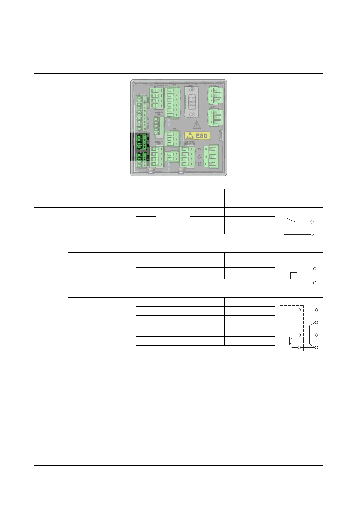
6.4.7 Binary outputs, optional boards
Slot Option/connection variant Symbol
OUT 6/7
OUT 8/9
OUT 10/11
OUT 12/13
Relay
Changeover contact
2× relay
Normally open contact
Solid state relay triac
230 V/1 A
2× solid state relay PhotoMOS®
50 V/200 mA
Binary output
0/22 V
2× binary output
0/12 V
a
a
PhotoMOS® is a registered trademark of Panasonic.
56
Page 57

WARNING!
L1
N
PE
L1
PE
N
Combining a mains voltage circuit with a protective low-voltage
circuit on the option "dual normally open contacts" is not permissible.
6.4.8 Mains power connection
6 Electrical connection
Connector/
Connection variant Symbol
terminal
PWR IN Mains power input
57
Page 58

6 Electrical connection
+
-
-
-
U
=
3
4
5
+
-
U
=
1
2
6.4.9 Voltage supply outputs
Optional board
Slot Connection variant Symbol
OUT 8/9 Voltage supply DC ±5V
for ISFET sensors
Voltage supply DC 24 V
for external transmitters 24 V
58
Page 59

6.4.10 Interfaces
RxD/TxD+
RxD/TxD-
1
2
1
5
41
Base unit interfaces
6 Electrical connection
Connector/
Connection variant Symbol
terminal
COM 1 RS485
Connector/
Connection variant Symbol
terminal
USB device USB device
Type Mini-B (socket)
USB host USB host
Type A (socket)
59
Page 60

6 Electrical connection
1 2 3 4
1 2 3 4
RxD+
RxD-
TxD+
TxD-
1
3
4
2
RxD/TxD+
RxD/TxD-
3
4
5
4
3
2
9
8
7
6
1
Optional board interfaces
Slot Connection variant Terminating resistors Symbol
COM 2 RS422
terminating resistors with
DIP switches on
optional board configurable
with terminating resistors
without terminating resistors
RS485
terminating resistors with
DIP switches on
optional board configurable
PROFIBUS-DP
3 = RxD/TxD-P
5 = DGND
6 = VP
8 = RxD/TxD-N
LAN Ethernet
Type RJ 45 (socket)
—
—
60
Page 61

7 Startup
WARNING!
Prior to startup, ensure that the device has been installed and connected properly and
in compliance with the installation instructions. Observe the safety instructions
in this description.
v Chapter 1 "Safety information", Page 13
CAUTION!
A backup battery is built into the device. Its purpose is to maintain data when
the device is switched off or if the voltage supply is interrupted. If the battery
approaches the end of its operating life (approximately 7 years) then a battery
prealarm will indicate that status. When the battery is empty a battery alarm will
indicate that status. The battery must be exchanged before it is empty. The battery must be exchanged by the JUMO Service department! In this case, send
in the device!
CAUTION!
The touchscreen must not be operated with sharp or pointed objects, as these
could damage the protective film and the touchscreen.
7.1 Initial startup
Step Action
1 Switch on the voltage supply to the device and wait until it has boot-
2 Select the operating language.
3 Log in as user "Master" or "Service" in order to have access to the
4 Set the date and time.
5 Make the basic settings for the device.
6 Configure the analog and binary inputs you wish to use.
7 Check the hardware functions of the device.
8 Calibrate any analysis sensors connected to the device.
9 The device is now ready for use. You can configure the displays
ed up.
configuration in the device menu.
v Chapter 8.2.1 "Log-on/Log-out", Page 78
v Chapter 9.1 "Date and time", Page 109
v Chapter 10.2 "Basic settings", Page 116
v Chapter 10.5 "Analog inputs", Page 121
v Chapter 10.7 "Digital inputs of base unit and optional boards",
Page 133
v Chapter 7.2 "Function test", Page 62
vChapter 12 "Calibration in general", Page 169
and functions of the device according to your needs.
61
Page 62

7 Startup
Sample screen:
Hardware Information
for an optional board
"Universal input"
7.2 Function test
Important hardware information is displayed in the "Device Info" menu.
The functionality of the device can be checked from here.
7.2.1 Checking the optional boards
Open the hardware information for the installed optional boards as follows:
Device Menu
A tab with hardware and software information for each correctly installed optional board now appears.
r Device Info r Slots
7.2.2 Checking sensors and inputs/outputs
If no tab appears for an optional board, the board was not recognized and there
is a hardware problem. In such cases, check whether the optional board concerned was installed correctly.
v Chapter 11 "Retrofitting optional boards", Page 161
If this is not successful, contact Technical Support at JUMO.
The contact data can be found on the back of these installation instructions.
To check correct operation of all inputs/outputs, you can display the current analog and binary values.
Device Menu
Depending on the type of input, up to 2 columns will be visible in the Device Info
screens for inputs.
• Compensated: Display value that is calculated from the value measured by
the sensor through use of an appropriate compensation method and after
taking the corresponding calibration values into account.
This suppresses incorrect measuring values that can be caused by outside
factors (e.g. temperature) or sensor wear (e.g. a dirty electrode).
• Uncompensated: Value measured by sensor (raw value of the measure-
ment input, e.g. pH measuring chain voltage)
These sensor values are subject to distortion caused by outside factors.
r Device Info r Inputs/Outputs
62
Page 63

7 Startup
Sample screen:
IN 7 measures
conductivity
IN 8 measures pH value
IN 9 to 10 are available
only on the JUMO
AQUIS touch S.
Display of uncompensated values is used primarily for diagnostic purposes.
The compensated values are used for the actual measurement of analysis
variables.
The following example considers analysis inputs in the form of a conductivity
measurement input and a pH measurement input.
The device calculates the (compensated) values of the process variable from
the (uncompensated) raw measurement data.
63
Page 64

7 Startup
64
Page 65

8.1 Operating concept
This chapter explains how to use the functions at the operating level (e.g. controller and data monitor) and access the menu structure for editing device settings. The JUMO AQUIS touch P is operated by means of the touchscreen,
using either a finger or stylus with a soft, rounded plastic tip.
CAUTION!
The touchscreen must not be operated with sharp or pointed objects, as these
could damage the protective film and the touchscreen.
CAUTION!
Use only a soft cloth to clean the touchscreen. Commercially available cleaners
may contain substances that damage the protective film and the display.
NOTE!
Operation depends on the user's rights. Operating and setting options are restricted, depending on the user who is logged in.
The "Master" and "Service" users have access to all menus and functions (factory setting).
v Chapter 8.1.1 "Passwords and user rights", Page 65
8 Operation
8.1.1 Passwords and user rights
The device has 4 users with factory-configured user names, passwords, and
user rights. The passwords in the device can be changed.
v Chapter 8.2.1 "Log-on/Log-out", Page 78
The JUMO PC setup program is needed to change user names and user rights.
v "User list", page 252
The following table provides an overview of the factory-set user accounts.
Factory-set passwords
Users Every-
Factory-set password - 20 110 3000 9200
User 2 User 1 Service Master
one
65
Page 66

8 Operation
User rights
Users
Factory-set user rights
Display of:
• Current measuring values on
overview and detailed
screens
• Configuration data
• parameters
• Device information
Display of:
• History of measurement data
in the recording function
• Event and alarm list
• Service data
User actions
• Acknowledge alarms
•Calibrate
• Read out history of measurement data in the recording
function
• Display and change user level parameters
• Read out service data
User actions
• Operate control functions
Change settings
• Changing the settings at the
perimeter level
• Set date and time
Configuration
• Initialize calibration
Configuration
• Configuration of all
functions
• Activate extra codes
Every-
one
User 2 User 1 Service Master
XXX X X
XX X X
XX X
XX
66
Page 67

8.1.2 Display and control elements
(4)(5) (7) (8)(6)(3)
(1)
(2)
8 Operation
(1) Touchscreen
(2) Toolbar with buttons for operation
(3) "Device menu" button with display of:
• Date and time
• Logged-in user
("Master" in the example)
• Remaining memory display in percent for recording function
(in the example: 100%)
(4) "Alarm/Event List" button
(5) "Select operation screen" button (direct selection of the desired opera-
tion screen)
(6) "Home" button (back to main screen)
(7) Placeholder for context-sensitive buttons
Assignment depends on the particular operation screen.
Specific buttons are shown in the placeholders on the operation screens
for the controller and recording functions.
(8) "Next operation screen" button (for scrolling through operation screens)
67
Page 68

8 Operation
8.1.3 Menu structure
At the operating level, 3 different navigation buttons are available to select appropriate screens for display and control of device functions.
The "Device menu" and "Alarm/event list" menu levels are also displayed by
means of corresponding buttons. The device menu contains submenus for setting, servicing, and diagnosing the device and its functions.
The memory manager opens automatically as soon as a USB flash drive is inserted into the USB host interface. It exchanges data between the device and
the flash drive.
68
Page 69

Overview of the menu structure
Home
Select
operator
display
Next
operator
display
Operating level
Navigation in the
operating loop
Configuration
Parameterization
User level
Function level
Service
Calibrate
touchscreen
Device info
Calibration
Login/logoff
Device settings
menue
Schreiber
Update auf USB
Secure hardware
remove
Memory
manager
Plug-in
USB flash drive
Alarm list
Event list
Alarm-/
event list
Recorder backup
to USB
Save configuration
to USB
Load configuration
from USB
Read out
Service data
Software
update
8 Operation
NOTE!
The "Recorder Update to USB" and "Recorder Backup to USB" items appear
in the "Memory Manager" menu only if the extra "Recording function" is enabled.
v Chapter 4.2 "Order details", Page 22
69
Page 70

8 Operation
(1)
(3)
(4)
(2)
(5)
(6)
(7)
(8)
(9)
(10)
(11)
(12)
(13)
(14)
(15)
(16)
Operation screens in the operation loop
Fig. Operation screen Description
(1) General screen 1 Freely configurable overview display of measuring values and digital sig(2) General screen 2
nal states
The overviews can be configured as a 2-part screen or a 4-part screen.
2-part screen:
Display of 2 primary and 2 secondary measured values per screen, 1 ad-
ditional measured value and 3 binary values.
4-part screen:
Display of 4 primary and 4 secondary measured values per screen, 1 ad-
ditional measured value and 3 binary values.
70
Page 71

8 Operation
Fig. Operation screen Description
(3) Detailed screen 1 Freely configurable large-section screen
(4) Detailed screen 2
(5) Detailed screen 3
(6) Detailed screen 4
(7) Detailed screen 5
(8) Detailed screen 6
(9) Diagram
group 1
(10) Diagram
group 2
(11) Process screen User-defined visualization screen that is freely configurable by means of
(12) Controller over-
view
(13) Controller screen
Controller 1
(14) Controller screen
Controller 2
(15) Controller screen
Controller 3
(16) Controller screen
Controller 4
Display of 1 main measuring value, 1 second measuring value, 1 addi-
tional value and up to 3 binary values, as well as additional visualization
of the main measuring value and the alarm limits for an analog input with
a bar graph
Up to 4 analog measuring values and 3 digital functions can be displayed
on a configurable recorder screen. Diagrams of disabled groups are not
available in the operation loop.
an editor in the PC setup program
v Chapter 19.8.10 "Process screens", Page 270
With the aid of static and dynamic graphic and display elements for ana-
log and binary values, it is possible to create a screen that displays the
process flow concerned in an especially vivid manner. If no process
screen is configured, none is available for the operation loop.
The active controller channels are visualized here in an overview
display. The controller overview becomes available as part of the oper-
ating loop only if at least 2 controllers are activated. The current setpoint
values, actual values and output levels are displayed for all active con-
trollers. In addition, the operating states of the controllers are displayed
(manual mode, hold, self-optimization).
The controllers are visualized in detail on the controller screens. The con-
troller screens are available as part of the operation loop only for the re-
spectively configured channels. The information displayed includes the
current setpoint value, actual value and output level. The binary values
of switching controller outputs are visualized. In addition, controls for set-
point value entry, manual output level control and self-optimization are
available. Access to the operating functions depends on the user rights
of the logged-in user.
71
Page 72

8 Operation
Display of invalid values
Invalid input signals/measured values or errors in the analog input configuration
are detected and shown in the measured value displays as follows:
Type of error Display
underrange: measuring range underflow
overrange: measuring range overflow
Compensation error: An error occurred when compensat-
ing for factors affecting the measurements of the analysis.
It is necessary to check the measuring circuits and settings
of the compensation signals and the configuration of the
analysis measuring input affected.
Invalid display value
Possible errors include:
Incorrect input signal:
An analog input has an incorrect signal
or an analog input was selected for
which an optional board is not even present.
Error in the formula used by the mathematics module:
The result from a formula is invalid (e.g.
division by zero)
Display overrun: The value to be displayed is outside the
limits of -99999 to +99999.
Example of display of invalid values:
72
Page 73

8.1.4 Entry of text and numbers
Selection of umlauts/
special characters
Selection from the text
Entry line
Dialogs for entry of text or numbers appear automatically when the corresponding entry field is tapped.
Text entry dialog
There are 2 special features in addition to conventional entry of characters:
• Special characters appear for selection automatically at those buttons that
contain special characters.
• The text list simplifies entry of frequently used character strings. A history
of character strings entered is stored internally in the device. These are then
available for selection in the text list and can be copied simply by tapping the
line for the entry.
8 Operation
73
Page 74

8 Operation
Number entry dialog
This dialog opens if an entry field for numerical values is tapped.
Special feature : The "Exp" button permits entry of an exponent as a power of
ten.
Procedure:
Enter the numerical base value
the entry
r Tap "Exp" r Enter the exponent r Confirm
Entry dialog buttons
Explanation Button
Confirm entry (the value entered is accepted and the dialog closed)
Cancel entry (the value entered is discarded and the dialog closed)
Delete 1 character
Delete entry line completely
Open text list (select from a history of character strings entered)
Entry of an exponent as a power of ten
74
Page 75

8.2 Device menu
"Device menu"
button
NOTE!
Operation depends on the user's rights. Operating and setting options are restricted, depending on the user who is logged in.
The "Master" and "Service" users have access to all menus and functions (factory setting).
v Chapter 8.1.1 "Passwords and user rights", Page 65
The device menu contains submenus for setting and configuring all device functions.
To open one of the submenus in the device menu, tap the corresponding entry.
The device menu is opened by tapping the "Device menu" button at the operating level.
v Chapter 8.1.2 "Display and control elements", Page 67
v Chapter 8.1.3 "Menu structure", Page 68
8 Operation
Device menu
items
Log-on/Log-out This is where the user logs on and logs out. In addition, pass-
words can be changed here.
v Chapter 8.2.1 "Log-on/Log-out", Page 78
calibration Sensor calibration can be configured and performed here. In
addition, current calibration values and the calibration logbook are displayed.
v Chapter 12 "Calibration in general", Page 169
Description
75
Page 76

8 Operation
Device menu
items
User level Permits fast and simple access to a
selection of up to 25 frequently needed parameters from the
parameter level and the configuration level.
No user level is configured at the factory. The user level must
be configured and loaded into the device with the aid of the
JUMO PC setup program. The "User Level" entry does not
appear in the device menu as long as no user level is configured.
Description
v Chapter 8.2.2 "User level", Page 79
Configuration Basic operation of the device inputs and outputs and the de-
vice functions is set here.
v Chapter 10 "Configuration", Page 115
Parameterization
Setting the date/time and controller parameter sets, as well
as pre-setting controller setpoint values.
Fixed numerical values can be defined in the "Manual values" submenu.
v Chapter 9 "Parameterization", Page 109
Functional level Manual operation of certain functions for testing and diag-
nostic purposes (e.g. start wash contact or reset counter)
v Chapter 8.2.3 "Functional level", Page 80
Device information
Information about the device hardware and software, viewing
of current analog and binary values for all device functions,
inputs, and outputs
v Chapter 8.2.4 "Device information", Page 82
Service Display and readout of service data for diagnostic purposes,
saving and loading of a default configuration and performance of the basic Ci base calibration for commissioning of
Ci analysis inputs (inductive conductivity)
v Chapter 8.2.5 "Service", Page 83
Calibrate
Touchscreen
Calibration of the touchscreen to ensure the reliability and
convenience of touch control
v Chapter 8.2.6 "Calibrating the touchscreen", Page 84
76
Page 77

8 Operation
(1)
(2)
(3)
To navigate in submenus, menu items are opened by tapping the folder icons
identified with a plus sign. Open menu structures are identified with a minus sign
and can be closed again by tapping the folder icon.
Currently open windows can be left either by tapping "Exit" or the "Close window" button. Data are saved automatically when an open window is closed. Settings that were changed in the submenus take effect.
(1) Close window
(2) Closed menu structure (plus sign)
(3) Open menu structure (minus sign)
77
Page 78

8 Operation
Change
password
Log out
user
Log out
user
Back to
Operating loop
8.2.1 Log-on/Log-out
To access the "Log-on/Log-out" menu, tap the "Device menu" button and then
select the "Log-on/Log-out" menu item. The user can log on/out here and
change passwords for the
currently configured user accounts.
An overview of the factory-configured users and their rights can be found in the
"User Management" chapter.
v Chapter 8.1.1 "Passwords and user rights", Page 65
After the re-authentication time has elapsed, a logged-on user is logged out automatically. It is then necessary to log on again.
The re-authentication timeout does not take effect if:
• The log-on/log-out dialog is open
• The memory manager is open
• During calibration of analysis sensors
• During calibration of the touchscreen
The re-authentication time is set using the JUMO PC setup program.
v Chapter 19.8.2 "User list", Page 252
78
Page 79

8.2.2 User level
To make an entry,
tap the display
field
The user level consists of a user-defined list of parameters and configuration
settings. You need the JUMO PC setup program to configure the user level.
v Chapter 19.8.5 "User level", Page 263
The user level can be opened from the device menu only if it has been configured beforehand with the aid of the PC setup program. If this has not been done,
there is no user level in the device menu.
Opening the user level provides easy and uncomplicated access to the selected
parameters and settings. These can be edited from here. The entry dialog is
opened by tapping the display field for a desired data point.
View of the user level (example)
8 Operation
NOTE!
Changing the date/time settings and the configuration data that are relevant for
recording of measurement data initiates a restart of measurement data recording by the data monitor or recording function. This is also the case if the change
is made from the user level. The restart terminates the current recording of
measurement data. In the case of the "Data monitor" function, the content of
the screen is deleted.
79
Page 80

8 Operation
8.2.3 Functional level
The functional level is used primarily for testing and diagnostic purposes. Analog
and binary values of the outputs can be controlled manually here. This may be
useful, for instance, for checking an individual piece of equipment in a plant.
When performing maintenance and repair work, counters for operating hours,
switching actions and flow rates can be reset.
WARNING!
When manually controlling equipment in a system, it is absolutely essential to
take appropriate measures to prevent personal injury and property damage.
Ensure that only qualified personnel has access to the functional level. The factory settings restrict access to just "Master" and "Service" users.
Functional level menu items:
• Flow rate: Display the current flow rate, display and reset the total quantity
counter
• Washtimer: Manually start the wash process, display the time remaining un-
til the wash process and the current binary value
• Analog outputs: Read and manually control the current values of analog
outputs
• Digital outputs: Read current binary values, manually control digital output
outputs
• Counters: Reset the counters (operating hours and service counters)
NOTE!
Manual control of analog and digital outputs is possible only if the "Enable
menu. mode" option is activated for the specific output in the configuration. In
general, actions at the function level can be executed only by the "Master" and
"Service" users.
v Chapter 10.6 "Analog outputs of base unit and optional boards", Page 132
v Chapter 10.8 "Digital outputs of base unit and optional boards", Page 134
v Chapter 8.2.1 "Log-on/Log-out", Page 78
80
Page 81

Manual control of analog/digital outputs
(1)
(2)
(3)
Activate the configuration setting "Enable menu mode" for the outputs you wish
to control manually. "Manual mode buttons" buttons for manual control for these
outputs then appear at the functional level. To adjust output values manually,
proceed as follows:
8 Operation
Select Device menu
"Manual mode: button
opens
An activated manual mode can be recognized by the green background of the
particular output value display at the functional level.
View of functional level analog outputs (example)
r Enter value r Confirm
r Functional Level r Analog or Digital Output tab r Tap
r Tap Output Display field r Entry dialog
(1) "Manual mode" button
(2) Yellow background: Manual mode off
(3) Green background: Manual mode active
Once "Manual mode" has been switched off, the output immediately returns to
the value assigned in its configuration. The output display is once again yellow.
81
Page 82

8 Operation
8.2.4 Device information
For testing and diagnostic purposes, the "Device info" menu provides access to
extensive data about the hardware and software of the device, as well as current
analog and binary values.
Device Info menu items:
• General: Information about the main board, device software and Ethernet
configuration
• Slots: Overview of populated expansion slots, display of diagnostic and ver-
sion information for the installed optional boards
• Inputs/outputs: Overview of all analog and binary values of the inputs and
outputs of the device
• Functions: This menu is particularly helpful when checking functions after
configuration changes. It contains detailed information about all internal
functions (math/logic, flow rate, limit value, timer, washtimer, counter, and
controller) via their current status.
• Ethernet info: Ethernet communication statistics for diagnosis by trained
personnel
82
Page 83

8.2.5 Service
Service Menu items
8 Operation
The "Service" menu is used for in-device troubleshooting and diagnostics. It is
intended primarily for trained personnel. When troubleshooting together with
Service, the operator can access data that the JUMO service technicians need
for diagnosis.
NOTE!
The Service menu appears in the Device menu only if a
user with corresponding user rights is logged in.
v Chapter 8.2.1 "Log-on/Log-out", Page 78
• Default-configuration: The operator can store the current device configu-
ration in the device's memory. This configuration can be reloaded as the active configuration at any time. This is important, for instance, to return to the
initial configuration after configuration changes made for testing purposes.
Configurations can also be saved with the PC setup program or on a USB
flash drive with the aid of the Memory Manager.
vChapter 8.4 "Memory Manager (USB flash drive)", Page 90
• Debug Window: The Debug window can be used to check the behavior of
the device software in detail. Data are displayed to assist the JUMO service
technicians during troubleshooting.
• Ci base calibration: The Ci base calibration is required when commission-
ing an optional board or sensor for inductive conductivity measurements and
can be performed here.
v Chapter 11.2 "Ci base calibration", Page 164
• Service data: Status information that can be evaluated by JUMO service
personnel for diagnostic purposes can be read here.
In addition, the "Service count." and "Internal data" are displayed. The
83
Page 84

8 Operation
service counters record the number of switching operations executed by the
digital outputs. The voltage of the backup battery and the board tempera-
ture are shown in the "Internal data".
CAUTION!
A backup battery is built into the device. Its purpose is to maintain data when
the device is switched off or if the voltage supply is interrupted. If the battery
approaches the end of its operating life (approximately 7 years) then a battery
prealarm will indicate that status. When the battery is empty a battery alarm will
indicate that status. The battery must be exchanged before it is empty. The battery must be exchanged by the JUMO Service department! In this case, send
in the device!
8.2.6 Calibrating the touchscreen
To ensure precise and reliable operation of touchscreen control, you can open
the "Calibrate touchscreen" menu.
The device then prompts you tap 4 points on the touchscreen.
Simply follow the instructions on the display.
84
Page 85

8.3 Alarm/Event list
"Alarm/
Event List"
button
The JUMO AQUIS touch P offers the option of configuring alarm functions and
event functions in numerous functions. In addition, the electronics of the JUMO
AQUIS touch P are self-monitoring and trigger corresponding preprogrammed
alarms and events in case the internal device malfunctions.
Alarms and events appear in the lists in chronological order. The respective list
is opened from the "Alarm/Event List" menu.
The alarm/event list is opened by tapping the "Alarm/event list" button at the operating level.
v Chapter 8.1.2 "Display and control elements", Page 67
v Chapter 8.1.3 "Menu structure", Page 68
8 Operation
85
Page 86

8 Operation
Acknowledge
collective/dosing alarm
Display descriptive text for
the selected entry in full
Back to
Operator level
Example:
Alarm list
8.3.1 Alarm list
The alarm list displays the current alarms. Alarms are cleared upon elimination
of the alarm condition. Each alarm triggers a "collective alarm". The alarm list
view contains buttons for viewing details about alarms and acknowledging collective and dosing alarms.
v "Acknowledging collective/dosing alarms", page 87
Alarms are visualized further by the color of the bell icon on the "Alarm/event list"
button, in the "Alarm list" menu item of the "Alarm/event list" menu and in the title
bar of the operation screens:
• red bell: at least 1 alarm present
• green bell: no alarms
Visualization of alarms in the title bar can be activated in the configuration. The
most recently occurring alarm then flashes red in the title bar of the operation
screens.
v Chapter 10.3.1 "General Information", Page 117
If the alarm from a measuring input disappears, the color of the respective measuring-value display changes in accordance with the color settings.
v Chapter 10.3.3 "Colors", Page 118
All alarms are available in the binary selector. In this way, digital outputs or other
internal functions of the device can be controlled via alarms.
86
Page 87

Acknowledging collective/dosing alarms
The collective alarm combines all alarms in the alarm list. It simplifies signaling
of one or several active alarms with external indicating devices or to control
rooms. The digital signal for the collective alarm is available in the binary selector in 2 versions:
• Collective alarm: Is triggered by the occurrence of any alarm and disap-
pears only after all alarms in the alarm list have been cleared.
• Collective alarm ack.: Is triggered by the occurrence of any alarm and dis-
appears when the alarm is acknowledged.
Selection of a collective alarm when configuring device functions and
digital outputs:
Binary selection
Collective alarm/Collective alarm ack.
Dosing alarms are triggered by the controllers if the absolute value of the control deviation is larger than the "alarm tolerance". An "alarm delay" can be set for
each dosing alarm. Dosing alarms and acknowledgment of them must be activated in the controller configuration. The "alarm tolerance" and "alarm delay"
settings are made in the controller parameters.
r Alarm and internal -signals r
vChapter 10.11.1 "Configuration of the controllers", Page 140
vChapter 9.2 "Parameter Sets (Controller parameter)", Page 110
8 Operation
Selection of a dosing alarm when configuring internal functions and digital outputs:
Binary selector
Collective and dosing alarms can be acknowledged with the "Confirm" button.
r Controller r Dosing Alarm Controller 1 to 4
87
Page 88

8 Operation
Display descriptive text for the selected entry in full
Back to
Operator level
Delete the
event list
8.3.2 Event list
A number of situations that are essential for tracking and diagnostic purposes
are logged in the event list. The entries are identified with corresponding icons
on the basis of the type of event. In addition, events are logged with an icon in
the data monitor/recording function.
Detailed information on the data monitor/recording function
v Chapter 8.6 "Operation of the data monitor/recording function", Page 99
88
Page 89

8 Operation
The following table provides an overview of the possible entries in the event list.
Events Symbol
Power on
Power off
Alarm occurred
Alarm cleared
• Configured event (condition occurred)
• Calibration start
•Timer start
• Wash contact start
• Controller manual mode on
• Controller self-optimization started
• Configured event (condition ended)
• Calibration stop/cancel
• Timer stop
• Wash contact stop
• Controller manual mode off
• Controller self-optimization ended
Comment entered
• Switch daylight saving time
• No connection to an input module
• Configuration change
• Reset counter
• Reset flow rate measurement
• Confirm collective alarm
No
symbol
89
Page 90

8 Operation
8.4 Memory Manager (USB flash drive)
The Memory manager is used to transfer data between the JUMO AQUIS touch
P and a USB flash drive. To open the memory manager, close all windows and
insert the USB flash drive into the USB host interface. The memory manager will
then open automatically. You require the relevant user rights for access to the
menu options "USB->Configure devices and "Software update". The factory settings authorize the "Master" and "Service" users for this.
v Chapter 8.1.1 "Passwords and user rights", Page 65
Memory Manager menu items:
• Safely remove hardware: To prevent hardware damage or loss of data, it is
necessary to select this menu item before removing and inserted USB flash
drive. Please follow the instructions on the device's display.
• Recorder Update -> USB: Use this function for regular retrieval of record-
er data and continuous archiving of measured-data histories.
Measurement data that have not yet been retrieved are stored on the flash
drive together with their configuration data.
The measurement data are stored in DAT files and the configuration data in
SET files. This data can be opened and evaluated with the aid of the JUMO
PCA3000 evaluation software. Data that has been read out is marked internally as retrieved and the available memory display is reset to 100%.
CAUTION!
Ensure that recorder updates are performed in a timely manner!
When the ring memory is full (display of remaining memory in device reads
0%), measurement data in the ring memory is lost (starting with the oldest).
• Recorder Backup -> USB: This function is used to back up the recorder
data to prevent data loss.
All measurement data in the ring memory (also data already retrieved) are
transmitted to the flash memory together with their configuration data.
The measurement data are stored in DAT files and the configuration data in
SET files. These files can be opened and evaluated with the aid of the JUMO
90
Page 91

8 Operation
PCA3000 evaluation software.
In contrast to Recorder Update, there is no internal marking of recorder data
and no resetting of the available memory display.
NOTE!
The "Recorder Update" and "Recorder Backup" functions are
available only if the extra code "Recording" is enabled.
NOTE!
A measuring data recording session is closed by changing configuration data
that are relevant to the data monitor or registration function (e.g. scaling or description of an analog channel). The measurement data accumulated since the
beginning of the current recording session are stored in the device in a file with
the extension "DAT" together with an additional file with the extension "SET".
A new recording session begins as soon as the new configuration goes into effect. One DAT file and one SET file are created for each recording session
when recorder data are retrieved via Update or Backup.
• Device Config. -> USB: The complete, current configuration of the device
is transmitted to the flash drive and saved in a file with the name
"KONF304.SET". If the flash drive already contains a configuration file, a security prompt appears asking whether you are sure you want to overwrite this
file. Pressing the "OK" button saves the current configuration to the flash
drive and overwrites the previous file.
91
Page 92

8 Operation
• USB -> Device config.: A configuration that is saved on the flash drive is
NOTE!
A check of version compatibility is performed when transferring device configurations from the USB flash memory to the device. If the device setup on the
USB flash drive is incompatible with the version of the device software, the
transfer is terminated. The second term of the device version number must be
greater than or equal to the second term of the device version number used to
create the device setup file. Examples of combinations of version levels:
Device software version used to create the configuration = 304.02.xx, device
software version of the destination device = 304.02.xx,
The versions are compatible
Device software version used to create the configuration = 304.01.xx, device
software version of the destination device = 304.02.xx,
The versions are not compatible
loaded into the device and activated as the current configuration. Only the
currently active configuration is overwritten. The
previous default configuration is retained. If desired, the current
configuration can be saved as the default configuration.
v Chapter "Service Menu items", Page 83
Device software version used to create the configuration = 304.02.xx, device
software version of the destination device = 304.01.xx,
The versions are not compatible
• Service data -> USB: A data record with service-relevant information about
the device is transmitted to the flash drive and saved in a file with the name
"DEBUG304.SET". The information can be used by JUMO Service for diagnostic purposes.
• Software Update: The device software can be updated with the aid of a
USB flash drive. To do so, an appropriate update file must have been saved
on
the flash drive in advance; this file can be obtained from JUMO Service.
CAUTION!
It is strongly recommended that the configuration and recorder data be backed
up
prior to performing a software update.
92
Page 93

8.5 Operating the controllers
NOTE!
Since the automatic control mode is of prime importance in the case of controllers,
correct configuration of the individual controller and its parameterization (adjustment of the control response) are very important for achieving good process
value stability.
Before commissioning a controller channel, ensure that all settings in the configuration and the parameterization are
correct.
v "Operating the controllers", page 93
v Chapter 9.2 "Parameter Sets (Controller parameter)", Page 110
NOTE!
In most cases, the parameterization are made automatically with the aid of
self-optimization. In exceptional cases, however, it may be necessary to determine
the controller parameters experimentally or to calculate them and then enter
them into the controller's parameter sets manually.
8 Operation
How to operate the 4 different operating modes (automatic mode, manual mode,
hold mode and self-optimization) is described in the following 4 subchapters.
93
Page 94

8 Operation
8.5.1 Automatic control mode
The automatic control mode is the normal operating mode used by the controller
to
maintain the actual value of a process variable at the specified setpoint. The
controller evaluates the control deviation and controls the output such that the
actual value of the process approaches the setpoint. Changes to the current setpoint can be made in the controller operation screen or in the "parameterization". Two setpoints are stored for each controller in the parameterization.
Setpoint 1 is active by default. Setpoint 2 can be activated instead of Setpoint 1
in each controller by means of "Setpoint selection". Setpoints can also be specified by external sources and transmitted to the controllers in the JUMO AQUIS
touch S via analog inputs. "Setpoint selection" and the configuration of external
setpoints are set in the "Setpoint configuration".
v Chapter 9.3 "Setpoint values", Page 113
v Chapter 10.12 "Setpoint value configuration", Page 147
94
Page 95

8 Operation
(1)
(2)
(3)
(5)
(6)
(7)
(8)
(4)
On the operation screen of each controller, it is possible to change the current
controller setpoint value, switch to the "Manual mode" or start "Self-optimization".
(1) Display of the digital controller output signals as indicator lights
(2) "Manual entry" button for changing the current setpoint value
A change to the currently active setpoint value is transferred to the controller parameters. When external setpoint values are used, this button is
hidden.
(3) Bar graph to display the current output level
(4) Start/cancel "self-optimization" button
Self-optimization is used to determine the optimal controller parameters
automatically.
(5) "Manual mode" on/off button
When manual mode is activated, the output level assumes a preconfig-
ured
value and can then be changed manually.
v Chapter 8.5.2 "Controller in the manual mode", Page 96
(6) Numerical display of the current output level
(7) Display of the current setpoint value
(8) Display of the current actual value
95
Page 96

8 Operation
(1)
(2)
(3)
(4)
(5)
(6) (7)
8.5.2 Controller in the manual mode
In manual mode, the user can manually control the controller outputs. The
controller outputs can be controlled in two ways:
• Entry of a numerical value: Using the "Manual entry" button,
the user can open a dialog to enter a fixed numerical value for the output.
• Jogging mode: Pressing and holding the arrow buttons sets the output to
±100% or the corresponding digital controller output to "on"
depending on the controller configuration. After the button is released, the
output level returns to
0% or the corresponding digital controller output level back to "off". This function is used to operate actuators (e.g. solenoid valves, dosing pumps or motorized positioners) manually. To protect the actuators, the output does not
change abruptly when the button is pressed, but rather in a continuous manner.
It is also possible to specify a manual output level in the configuration in order
to ensure that a "safety output level" is generated when changing to the manual
mode.
The manual output level is preset in the controller configuration.
v Chapter 10.11 "Controller", Page 140
96
(1) Display of the digital controller output signals as indicator lights
(2) Display of active manual mode
(3) "Manual entry" button for entering the manual output level
(4) "Jogging mode" button for manual control of actuators
• Down arrow for output level = -100% or digital controller output off
(only for three-point, three-point step controllers and continuous controllers with integral position controller)
• Up arrow for output level = +100% or digital controller output on
(5) "Manual mode" on/off button
(6) Bar graph to display the current output level
(7) Numerical display of the current output level
Page 97

8.5.3 Hold mode
(1)
(2)
The hold mode of a controller is activated in two ways:
• Calibration of the actual-value input
• Hold signal for the individual controller (specified in the controller configura-
In the hold mode, automatic control is suspended. The controller generates the
preconfigured value as output level unless acceptance of the hold output is disabled in the configuration. In this case, the output level is frozen.
Only the setpoint value can be changed in this operating mode. In the hold
mode, however, the setpoint value change has no effect. The changed setpoint
value takes effect only when the controller returns to the automatic control
mode.
The hold mode has priority over the manual mode. If the hold mode is activated
while the controller is in the manual mode, the controller changes from
manual mode to hold mode and then returns to manual mode when hold mode
is deactivated.
The hold output level is preset and the digital signal for
activating hold mode is set in the controller configuration.
v Chapter 10.11 "Controller", Page 140
8 Operation
tion)
(1) Display of active hold mode
(2) "Manual entry" button for changing the current setpoint. The change to
the currently active setpoint is transferred to the controller parameters.
The output level, however, remains frozen during hold mode.
When external setpoint values are used, this button is hidden.
To configure external setpoint values:
v Chapter 10.12 "Setpoint value configuration", Page 147
97
Page 98

8 Operation
(1)
(4)
(5)
(6)
(7)
(2)(3)
8.5.4 Optimizing controllers
The control response can be optimized by entering known controller parameters
manually or automatically by means of "self-optimization". During self-optimization, the individual controller determines the mathematical parameters for a process. The controller changes the output level (step change) and evaluates the
response of the actual value in the process (step response). Following successful self-optimization, the controller parameters determined in this way are adopted in the "Parameterization" function
v Chapter 9.2 "Parameter Sets (Controller parameter)", Page 110
WARNING!
During self-optimization, the controller outputs assume unpredictable values!
Before a self-optimization starts, it must be ensured that greater deviations between the actual value and the set setpoint value do not cause property damage
or physical injury.
(1) Display of active self-optimization
(2) Start/cancel "self-optimization" button
(3) Button for changing the current setpoint value
Changing the setpoint values during self-optimization is not possible.
(4) Bar graph to display the current output level
(5) Numerical display of the current output level
(6) Display of the current setpoint value
(7) Display of the current actual value
98
Page 99

8 Operation
Features
Function
8.6 Operation of the data monitor/recording function
The standard version of the JUMO AQUIS touch P is equipped with a data monitor. It is used to record and view the analog measuring value and signal states
of digital functions. Two groups are available, each of which can record up to 4
analog values and 3 binary values and display them in the form of a line recorder
diagram. There is a separate diagram for each group in the operation loop.
The recording function represents an Add-On to the data monitor and is
available as an extra code.
v Chapter 4.2 "Order details", Page 22
The features of the data monitor and recording function are listed in the
following table:
Data monitor Recording
Measured-data recording
Recording of the measuring values from up to 4 analog channels
and display of the measuring values in the form of a line recorder
diagram
XX
Digital data recording
Recording of the binary values
from up to 3 digital channels and
display of the digital data in the
form of a binary channel
diagram
Displaying events
Event list entries are shown as
icons in the line recorder diagram
History function
For scrolling the line recorder
diagram to the past to view
measurement data and events
from farther back in time
Zoom function
The time range is compressed to
view measured-data histories
over longer periods in one area of
the screen
Measurement data retrieval
for archiving recorded
measurement data and
evaluating the data via
JUMO PCC/PCA3000
XX
XX
X
X
X
99
Page 100

(1)
(2)(3)
(4)
(5)
 Loading...