

Page 1

JUMO GmbH & Co. KG
Delivery address: Mackenrodtstraße 14
36039 Fulda, Germany
Postal address:
36035 Fulda, Germany
Phone: +49 661 6003-0
Fax: +49 661 6003-607
Email: mail@jumo.net
Internet: www.jumo.net
JUMO Instrument Co. Ltd.
JUMO House
Temple Bank, Riverway
Harlow, Essex CM20 2DY, UK
Phone: +44 1279 635533
Fax: +44 1279 635262
Email: sales@jumo.co.uk
Internet: www.jumo.co.uk
JUMO Process Control, Inc.
6733 Myers Road
East Syracuse, NY 13057, USA
Phone: 315-437-5866
1-800-554-5866
Fax: 315-437-5860
Email: info.us@jumo.net
Internet: www.jumousa.com
JUMO AQUIS 500 CR
Transmitter/controller
2 analog inputs
Input 1:
Conductivity / resistivity
1 binary input
For floating contact
Functions:
- key inhibit
- alarm stop
- HOLD
Supply voltage
110—240 V AC
12—24 V DC
20—30 V AC/DC
Analog outputs (option)
Output 1 + 2:
0(4)—20 mA or 0—10 V
option
Setup interface
Switching outputs (option)
Outputs 3 + 4:
- relay, changeover (SPDT)
User-friendly configuration
Reloading of languages
Plant documentation
Configurable as analog process
value output and/or continuous
controller output (PID action)
Configurable as
- limit controller
- pulse width output
(PID action)
- pulse frequency output
(PID action)
- modulating controller
(PID action)
- USP contact
- "Purified water" contact
as per Ph.Eur.
- calibration timer run down
standard
Input 2:
Temperature
manual input or automatic
Pt100 / Pt1000 / 4 kΩ
Transmitter/Controller
for conductivity, TDS, resistivity
and temperature
Brief description
The instrument is used for the conductive measurement/control of electrolytic conductivity,
resistivity or the TDS value. In addition, the JUMO AQUIS 500 CR also offers the possibility of
showing the measured conductivity according to a customer-specific table.
Conductive two-electrode cells as well as four-electrode cells can be connected to the
instrument.
Temperature serves as the second input variable, measured by a Pt100/1000 probe. Depending
on the measured variable, it is therefore possible to implement specific, automatic temperature
compensation.
The instrument is operated using keys and a large LC graphics display on which the
measurements are clearly legible. The plain-text presentation of the parameters makes it easier
for the user to configure the instrument, and also helps in programming it correctly.
Thanks to its modular design, the instrument can be perfectly matched to the particular
application requirement. Up to four outputs are available (see the block diagram for the
functions).
Typical areas of application
Universally applicable in water and wastewater engineering, service/process water and
wastewater, drinking water and well/surface water, pure and high-purity water as well as for
pharmaceutical water (e.g. as per USP, Ph.Eur., WFI), water quality measurements, TDS
measurements (ppm or mg/l).
Block diagram
Approvals/approval marks (see Technical data)
V1.00/EN/00477047
Data Sheet 202565
h
t
i
w
t
n
a
>
i
l
5
4
p
6
m
<
o
P
C
S
U
Key features
• Direct changeover to
- conductivity (µS/cm or mS/cm)
- resistivity (kΩ x cm or MΩ x cm)
- TDS measurement (ppm or mg/l)
- customer-specific table
• Automatic temperature compensation:
off (e.g. USP), linear, ASTM, natural water
(EN 27888/ISO 7888)
• Large LC graphics display with
background lighting
• Choice of display: large numbers, bar
graph or trend display
• Calibration options according to
measured variable: cell constant and
temperature coefficient
• Calibration logbook
• Two-electrode cells (as standard) or
four-electrode cells can be connected
• Pollution detection can be activated
• Auto-range operation
• IP67 enclosure protection
(in surface mountable housing)
IP65 enclosure protection
(for panel mounting)
• Language changeover:
German, English, French;
further languages can be loaded through
the setup program
• Using the setup program: user-friendly
programming, plant documentation,
additional languages can be loaded
Page 1/12
Type 202565
Page 2
Page 2/12Data Sheet 202565
JUMO GmbH & Co. KG
Delivery address: Mackenrodtstraße 14
36039 Fulda, Germany
Postal address:
36035 Fulda, Germany
Phone: +49 661 6003-0
Fax: +49 661 6003-607
Email: mail@jumo.net
Internet: www.jumo.net
JUMO Instrument Co. Ltd.
JUMO House
Temple Bank, Riverway
Harlow, Essex CM20 2DY, UK
Phone: +44 1279 635533
Fax: +44 1279 635262
Email: sales@jumo.co.uk
Internet: www.jumo.co.uk
JUMO Process Control, Inc.
6733 Myers Road
East Syracuse, NY 13057, USA
Phone: 315-437-5866
1-800-554-5866
Fax: 315-437-5860
Email: info.us@jumo.net
Internet: www.jumousa.com
(1)
(2)
(4)
(5)
(6)
(7)
(8)
(9)
(3)
Functional description
The instrument is designed for use on site. A
rugged housing protects the electronics and
the electrical connections from corrosive
environmental conditions (IP67). As an
alternative, the instrument can also be
installed in a control panel, and is then
protected to IP65 on the front. The electrical
connection is made by easy-to-fit pluggable
screw terminals.
Transmitter
Two-electrode cells (standard) as well as fourelectrode cells can be used for measurement.
Two-electrode cells can be connected, in the
usual increments for cell constants (K=0.01;
0.1; 1.0; 3.0 and 10.0). Thanks to the widely
adjustable relative cell constant, it is also
possible to connect sensors with different cell
constants (e.g. K=0.2).
In the case of the 4-electrode cells, the values
K=0.5 and 1.0 have been predefined for the
cell constant. Here too, the instrument can be
matched to sensors with different cell
constants (e.g. K=0.4).
The instrument can perform automatic
temperature compensation, by acquiring the
temperature of the sample solution.
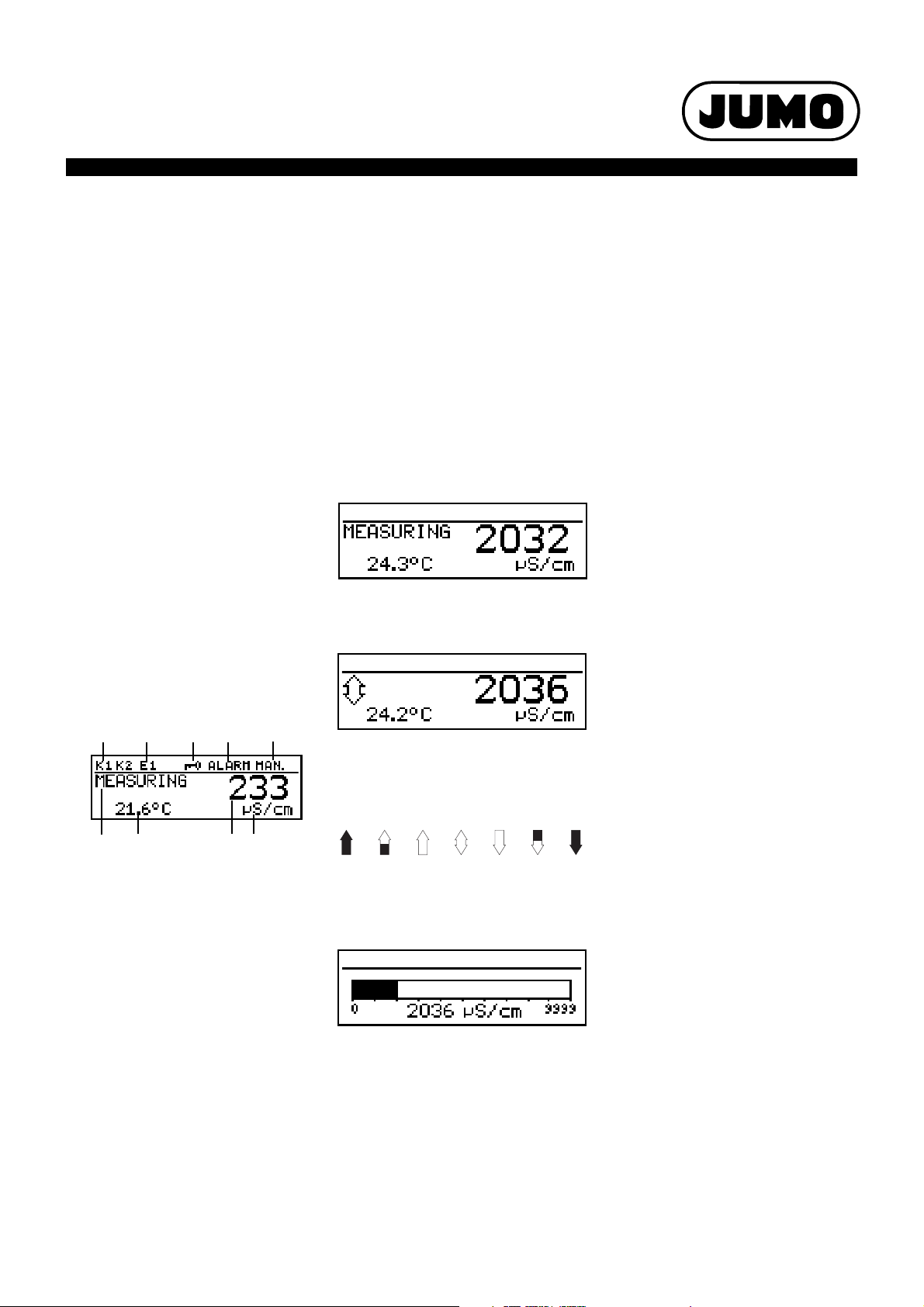
Displays and controls
(1) Switching output 1 or 2 is active
(2) Binary input 1 is actuated
(3) Keypad is inhibited
(4) Alarm has been activated
(5) Instrument is in manual mode
(6) Instrument status
(7) Temperature of medium
(8) Principal measurement
(9) Unit of principal measurement
The user can define what is to be shown in
positions (7) and (8) of the display:
•no display
• compensated or uncompensated
measurement
•temperature
• output level 1 or 2
•setpoint 1 or 2
V1.00/EN/00477047
Operation
For easy programming and operation, all
parameters are arranged in clearly structured
levels and shown in plain text. Operation is
protected by a code word. This facilitates
individual adaptation of the operation, since
parameters can be generally enabled or
specifically assigned to the protected area.
As an alternative to configuration from the
keys, the instrument can also be configured
through the convenient setup program for PC
(option).
Display modes
Three display modes are available:
Large numbers
In this display mode, the measurements are
shown in digits, as usual.
Tre n d display
The numerical value is supplemented by a
symbol which indicates the change direction
and change speed of the measurement.
This can, for instance, be very useful during
controller optimization.
from left to right:
fast, medium and slow rise, stable,
slow, medium and fast fall.
Bar graph
This display mode allows the user to see at a
glance in which region the measurement is at
present.
The bar graph can be freely scaled.
Function modes
Electrolytic conductivity
Display/control, unit µS/cm or mS/cm.
Resistivity (high-purity water)
Display/control, unit kΩ x cm or MΩ x cm.
TDS
Display/ control with ppm for the unit.
In this mode, the specific TDS factor can be
entered in addition.
Customer-specific table
In this mode, the input value (conductivity or
resistivity) can be displayed in accordance
with a table (up to 20 value pairs). Thanks to
this function, it is possible to implement
simple concentration measurements, for
example. The values in the table can only be
entered through the optional setup program.
Calibration
Cell constant
Because of manufacturing tolerances, the cell
constant of a conductivity cell may deviate
slightly from its nominal value. In addition, the
cell constant may change during operation
(due to deposits or wear, for example). This
results in a change of the output signal from
the cell. The instrument provides the user with
the possibility of compensating any deviation
from the nominal value of the cell constant by
manual entry or automatic calibration of the
relative cell constant. A manual entry is used,
for instance, for calibration during high-purity
water measurement.
Temperature coefficient
The conductivity of almost all solutions
depends on the temperature. To ensure
correct measurement, it is therefore
necessary to know both the temperature and
the temperature coefficient [%/°C] of the
sample solution. The temperature can either
be measured automatically, with a Pt100 or
Pt1000 temperature probe, or it has to be set
manually by the user.
The temperature coefficient can be
automatically determined by the instrument,
or it can be entered manually.
Calibration logbook
The five most recent successful calibrations
can be called up in the calibration logbook.
This makes it possible to evaluate the ageing
of the sensor that is connected.
Calibration timer
The calibration timer indicates (if required)
when the next routine calibration is due. The
calibration timer is activated by entering a
number of days, after which recalibration has
to be carried out (plant or operator
requirement).
MIN / MAX value memory
This memory acquires the minimum or
maximum input variables that have occurred.
This information serves, for example, to
decide whether the sensor that is connected
is suited to the values that are actually
present.
Page 3

Page 3/12Data Sheet 202565
JUMO GmbH & Co. KG
Delivery address: Mackenrodtstraße 14
36039 Fulda, Germany
Postal address:
36035 Fulda, Germany
Phone: +49 661 6003-0
Fax: +49 661 6003-607
Email: mail@jumo.net
Internet: www.jumo.net
JUMO Instrument Co. Ltd.
JUMO House
Temple Bank, Riverway
Harlow, Essex CM20 2DY, UK
Phone: +44 1279 635533
Fax: +44 1279 635262
Email: sales@jumo.co.uk
Internet: www.jumo.co.uk
JUMO Process Control, Inc.
6733 Myers Road
East Syracuse, NY 13057, USA
Phone: 315-437-5866
1-800-554-5866
Fax: 315-437-5860
Email: info.us@jumo.net
Internet: www.jumousa.com
Hysteresis
Setpoint
pH
On
Off
Limit
Hysteresis
Limit
pH
On
Off
Setpoint
Hysteresis
Setpoint
pH
On
Off
Limit
Distance
Hysteresis
Setpoint
pH
On
Off
Limit
Distance
Time
On
Off
Pulse duration
Pulse
contact
Time
On
Off
Trigger
condition
Detection of deposits
Deposit detection can be activated for 4electrode cells.
During normal operation, it can happen that
deposits form on electrodes. This has the
result that a lower concentration is displayed
than actually present. With activated “deposit
detection” function, the instrument tells you
when the cell needs to be serviced.
Auto-range
For some processes, the availability of two
measuring ranges is advantageous, for
instance for rinsing or regeneration
processes.
What is usually required here, is the precise
acquisition of a low conductivity. Rinsing or
regeneration, however, involves a much
higher conductivity, which could lead to an
out-of-range condition (error). This situation is
not just unsatisfactory, but may even be
dangerous. Thanks to the auto-range
function, two measuring ranges can be
determined. The instrument then switches
between them in a defined manner.
Binary input
The following functions can be activated
through the binary input:
• Activate key inhibit
When this function has been activated,
operation from the keys is no longer
possible.
• Activate HOLD mode
After activating this function, the outputs
(analog and relay) adopt the states that
have previously been defined.
• Alarm suppression (controller alarm only)
This function temporarily deactivates the
alarm generation via the relay (has to be
configured accordingly).
Linking the corresponding terminals by
means of a floating contact (e. g. relay) will
activate the pre-defined function.
Control functions
The relays can have functions assigned that
are configured via parameters. The control
function is freely programmable as P, PI, PD or
PID action.
Relay outputs
Two relay changeover contacts are available
for the principle measurement variable and/or
temperature.
The following functions can be programmed:
• Switching direction
(min/max)
• Limit controller
(pull-in/drop-out delay, hysteresis)
• Pulse width output
(see control functions)
• Pulse frequency output
(see control functions)
• Modulating controller function
(see control functions)
• Limit comparators
(pull-in/drop-out delay, hysteresis)
• Pulse function
The output switches on briefly when
reaching the switching point and then off
again.
•Alarm
• Sensor or range error
• Response to alarm, over/underrange,
calibration and HOLD
Contact functions
MAX limit comparator
MIN limit comparator
Alarm window 1
Alarm window 2
Pulse contact
Trigger condition longer than pulse
duration
Analog Outputs
There are up to 2 analog outputs available.
The following functions can be selected:
Output Analog process value output Continuous controller
Main variable Temperature
1X-X
2-XX
With the analog process value output, the range start and end values are freely selectable.
The response of the outputs to over/underrange, alarm and calibration is freely programmable.
Simulation function: The analog process value outputs can be freely set in the manual ("Hand")
Application: "Dry run" start-up of the plant, troubleshooting, servicing.
V1.00/EN/00477047
mode.
main value
Page 4

Page 4/12Data Sheet 202565
JUMO GmbH & Co. KG
Delivery address: Mackenrodtstraße 14
36039 Fulda, Germany
Postal address:
36035 Fulda, Germany
Phone: +49 661 6003-0
Fax: +49 661 6003-607
Email: mail@jumo.net
Internet: www.jumo.net
JUMO Instrument Co. Ltd.
JUMO House
Temple Bank, Riverway
Harlow, Essex CM20 2DY, UK
Phone: +44 1279 635533
Fax: +44 1279 635262
Email: sales@jumo.co.uk
Internet: www.jumo.co.uk
JUMO Process Control, Inc.
6733 Myers Road
East Syracuse, NY 13057, USA
Phone: 315-437-5866
1-800-554-5866
Fax: 315-437-5860
Email: info.us@jumo.net
Internet: www.jumousa.com
Time
On
Off
Pulse duration
Pulse
contact
Time
On
Off
Trigger
condition
Process value X
Setpoint W
Proportional band X
P
100%
50%
0%
Output level y
Switching period
10%
90%
90%
10%
t
On
50%
50%
t
Off
10%
90%
X
P
X - W
0
1
100%
50%
0%
No pulses
50% of pulse frequency
Maximum pulse frequency
Setpoint W
Proportional band X
P
X
P
X - W
0
1
Output level y
Process value X
Pulse contact
Trigger condition shorter than pulse
Pulse width controller
(output is active with X > W and P action)
duration
If the process value X exceeds the setpoint W,
the P controller will control proportionally to
the control deviation. On going outside the
proportional band, the controller operates
with an output level of 100 % (100 % duty
cycle).
Measuring ranges / cell constants
This state-of-the art instrument offers a far wider dynamic range on the input side than can be
managed physically or chemically by the conductivity cells. For this reason, the range must be
matched to the operating range of the cell.
Examples of ranges for combination
with 2-electrode cells
Cell constant (K) Recommended/practical measuring span
0.01 1/cm 0.05 µS/cm to 20 µs/cm
0.1 1/cm 1 µS/cm to 1000 µs/cm
1.0 1/cm 0.01 mS/cm to 100 ms/cm
3.01/cm 0.1mS/cmto30ms/cm
10.0 1/cm 0.1 mS/cm to 200 ms/cm
(depending on the conductivity cell)
Pulse frequency controller
(output is active with X > W and P action)
If the process value X exceeds the setpoint W,
the P controller will control proportionally to
the control deviation. On going outside the
proportional band, the controller operates
with an output level of 100 % (maximum
switching frequency).
It is assumed that the measuring span of the
instrument is always larger than the
recommended or practically usable range of
the conductivity cell.
The smaller range (instrument or conductivity
cell) determines the maximum range that can
be used.
Example
Which span can the instrument cover with a
predefined cell constant?
The predefined cell constant is K=0.4
The span of the instrument is
0.1 µS/cm x 0.4 1/cm to
1250 mS/cm x 0.4 1/cm
➝ 0.04 µS/cm — 500 mS/cm
Example
A measurement is to be carried out in the 10 µS/cm to 500 µS/cm range. A conductivity cell with
the cell constant K = 0.1 1/cm is chosen.
The unit µS/cm without a decimal place is configured on the instrument.
Combination with 4-electrode cells and 2-electrode cells
having cell constants that deviate from the above graduation
This requires taking a closer look at the instrument technology and considering both the
uncompensated and the temperature-compensated measuring span.
The uncompensated measuring span of the instrument is calculated according to the formula:
Measuring span = 0.1 µs/cm x cell constant (K) to 2500 mS x cell constant (K).
After taking account of the temperature compensation range, the following compensated
measuring span (approx.) will remain:
Measuring span = 0.1 µs/cm x cell constant (K) to 1250 mS x cell constant (K).
Cell constant (K) Measuring span covered by instrument
0.01 0.001 µS/cm to 1.25 ms/cm
0.1 0.01 µS/cm to 12.5 ms/cm
1.0 0.1 µS/cm to 125 ms/cm
3.0 0.3 µS/cm to 375 ms/cm
10.0 0.1 mS/cm to 1250 ms/cm
V1.00/EN/00477047
(temperature-compensated)
Page 5

JUMO GmbH & Co. KG
Delivery address: Mackenrodtstraße 14
36039 Fulda, Germany
Postal address:
36035 Fulda, Germany
Phone: +49 661 6003-0
Fax: +49 661 6003-607
Email: mail@jumo.net
Internet: www.jumo.net
JUMO Instrument Co. Ltd.
JUMO House
Temple Bank, Riverway
Harlow, Essex CM20 2DY, UK
Phone: +44 1279 635533
Fax: +44 1279 635262
Email: sales@jumo.co.uk
Internet: www.jumo.co.uk
JUMO Process Control, Inc.
6733 Myers Road
East Syracuse, NY 13057, USA
Phone: 315-437-5866
1-800-554-5866
Fax: 315-437-5860
Email: info.us@jumo.net
Internet: www.jumousa.com
Technical data
Inputs
Principal input Indication range Accuracy Temperature error
µS/cm 0.000 v 9.999
00.00 to 99.99
000.0 to 999.9
0000 to 9999
mS/cm 0.000 to 9.999
00.00 to 99.99
000.0 to 999.9
0000 to 9999
kΩ x cm 0.000 to 9.999
00.00 to 99.99
000.0 to 999.9
0000 to 9999
MΩ x cm 0.000 to 9.999
00.00 to 99.99
000.0 to 999.9
0000 to 9999
≤ 0.6 % of range + 0.3 µS x cell
constant (K)
≤ 0.6 % of range + 0.3 µS x cell
constant (K)
≤ 0.6 % of range + 0.3 µS x cell
constant (K)
≤ 0.6 % of range + 0.3 µS x cell
constant (K)
0.2%/10°C
0.2%/10°C
0.2%/10°C
0.2%/10°C
Page 5/12Data Sheet 202565
Secondary input Measuring range Accuracy Temperature error
Temperature Pt100
(automatic detection)
Temperature Pt1000
(automatic detection)
Temperature
NTC/PTC
-50 to +250°C
max. 4 kOhm
Input via table
a
±0,5 K (up to 100 °C)
0.05 %/10 °C
±0,8 K (as of 100 °C)
±0,5 K (up to 100 °C)
±1,0 K (as of 100 °C)
b
≤ 0.3 %
0.05 %/10 °C
with 20 value pairs,
through setup program
a
Switchable to °F
b
Depending on interpolation points.
Temperature compensation
Type of compensation Range
Linear 0 to 8 %/°C -10 to 160 °C
ASTM D1125 - 95 (high-purity water) 0 to 100 °C
Natural water (ISO 7888) 0 to 36 °C
Reference temperature
adjustable from 15 to 30 °C; preset to 25 °C (standard)
a
Please note operating temperature range of sensor.
a
Measuring circuit monitoring
Inputs Over/underrange Short-circuit Cable break
Conductivity yes depending on range depending on range
Temperature yes yes yes
2-electrode systems
Cell constant
[1/cm]
0.01
0.1 0.02 to 0.5
1.0 0.2 to 5
3.0 0.6 to 15
10.0 2.0 to 50
V1.00/EN/00477047
Setting range of
relative cell constant
20 to 500 %
Resulting usable
range [1/cm]
0.002 to 0.05
Page 6

Page 6/12Data Sheet 202565
JUMO GmbH & Co. KG
Delivery address: Mackenrodtstraße 14
36039 Fulda, Germany
Postal address:
36035 Fulda, Germany
Phone: +49 661 6003-0
Fax: +49 661 6003-607
Email: mail@jumo.net
Internet: www.jumo.net
JUMO Instrument Co. Ltd.
JUMO House
Temple Bank, Riverway
Harlow, Essex CM20 2DY, UK
Phone: +44 1279 635533
Fax: +44 1279 635262
Email: sales@jumo.co.uk
Internet: www.jumo.co.uk
JUMO Process Control, Inc.
6733 Myers Road
East Syracuse, NY 13057, USA
Phone: 315-437-5866
1-800-554-5866
Fax: 315-437-5860
Email: info.us@jumo.net
Internet: www.jumousa.com
4-electrode systems
Cell constant
[1/cm]
0.5
1.0 0.2 to 1.5
Setting range of
relative cell constant
20 to 150 %
Resulting usable
range [1/cm]
0.1 to 0.75
Binary input
Activation through floating contact
Function key inhibit
HOLD
alarm suppression
Controller
Controller type limit comparators, limit controller, pulse width controller, pulse frequency controller, modulating controller,
Controller action P/PI/PD/PID
A/D converter dynamic resolution up to 14-bit
Sampling time 500 msec
continuous controller
Analog outputs (one or two)
Output mode Signal range Accuracy Temperature error Permissible
load resistance
Current signal 0/4 to 20 mA ≤ 0.25 % 0.08 %/10 °C ≤ 500 Ω
Voltage signal 0 to 10 V ≤ 0.25 % 0.08 %/10 °C ≥ 500 Ω
The analog outputs respond in accordance with the recommendation as per NAMUR NE43.
They are electrically isolated, AC 30 V/DC 50 V.
Switching outputs (two changeover (SPDT) max.)
Rated load 3 A/250 VAC (resistive load)
Contact life >2x10
5
operations at rated load
Setup interface
Interface for configuring the instrument through the optionally available setup program (for instrument configuration only).
Electrical data
Supply voltage AC 110 to 240 V; -15/+10 %; 48 to 63 Hz
AC/DC20to30V; 48to63Hz
DC 12 to 24 V; +/-15 % (permissible only for connection to SELV/PELV circuits)
Power consumption approx. 14 VA
Electrical safety EN 61 010, Part 1
overvoltage category III
a
, pollution degree 2
Data backup EEPROM
Electrical connection pluggable screw terminals
conductor cross-section up to 2.5 mm
conductor cross-section up to 1.5 mm
a
Not valid with protective extra-low voltage (PELV) of power supply variant DC 12 to 24 V.
2
(supply, relay outputs, sensor inputs)
2
(analog outputs)
Display
Graphics LC display 120 x 32 pixels
Background lighting programmable:
- off
- on for 60 seconds during operation
V1.00/EN/00477047
Page 7

JUMO GmbH & Co. KG
Delivery address: Mackenrodtstraße 14
36039 Fulda, Germany
Postal address:
36035 Fulda, Germany
Phone: +49 661 6003-0
Fax: +49 661 6003-607
Email: mail@jumo.net
Internet: www.jumo.net
JUMO Instrument Co. Ltd.
JUMO House
Temple Bank, Riverway
Harlow, Essex CM20 2DY, UK
Phone: +44 1279 635533
Fax: +44 1279 635262
Email: sales@jumo.co.uk
Internet: www.jumo.co.uk
JUMO Process Control, Inc.
6733 Myers Road
East Syracuse, NY 13057, USA
Phone: 315-437-5866
1-800-554-5866
Fax: 315-437-5860
Email: info.us@jumo.net
Internet: www.jumousa.com
Housing
Material ABS
Cable entry cable glands, 3xM16 and 2xM12 max.
Special feature venting device to prevent condensation
Ambient temperature range
-10 to +50°C
(the specified accuracy is adhered
to within this range)
Operating temperature range
-15 to +65°C
(instrument is operational)
Storage temperature range -30 to +70°C
Climatic conditions rel. humidity ≤ 90 % annual mean, no condensation
(following EN 60721 3-3 3K3)
Enclosure protection
as per EN 60529
in surface mountable housing: IP67
for panel mounting: IP65 front, IP20 rear
Vibration strength as per EN 60068-2-6
Weight surface mountable housing: approx. 900 g
for panel mounting: approx. 480 g
Dimensions see dimensioned drawings on page 10.
Standard accessories
Cable glands
Internal mounting material
Operating Instructions
Page 7/12Data Sheet 202565
Approvals/approval marks
Mark of confirmity Testing laboratory Certifikates/certification numbers Test basis valid for
c UL us Underwriters Laboratories E 201387 UL 61010-1 all versions
V1.00/EN/00477047
Page 8

JUMO GmbH & Co. KG
Delivery address: Mackenrodtstraße 14
36039 Fulda, Germany
Postal address:
36035 Fulda, Germany
Phone: +49 661 6003-0
Fax: +49 661 6003-607
Email: mail@jumo.net
Internet: www.jumo.net
JUMO Instrument Co. Ltd.
JUMO House
Temple Bank, Riverway
Harlow, Essex CM20 2DY, UK
Phone: +44 1279 635533
Fax: +44 1279 635262
Email: sales@jumo.co.uk
Internet: www.jumo.co.uk
JUMO Process Control, Inc.
6733 Myers Road
East Syracuse, NY 13057, USA
Phone: 315-437-5866
1-800-554-5866
Fax: 315-437-5860
Email: info.us@jumo.net
Internet: www.jumousa.com
Electrical connection
The electrical connection for the “surface mountable housing”
version can be made easily, after opening the unit.
Clamp (screen)
Row 1
Row 2
The connection cable between sensor and transmitter must
be a screened cable with a diameter of 8 mm max.
The instrument contains a guide plate for an optimized cable
routing.
The sensor cables (incorporating strain relief) are run to the
pluggable screw terminals where they are connected without
using any solder.
Page 8/12Data Sheet 202565
Connection Te rm i na l Ro w
Supply for transmitter/controller
Supply voltage (23): AC 110 to 240 V; -15/+10 %; 48 to 63 Hz
Supply voltage (25): AC/DC 20 to 30 V; 48 to 63 Hz
Supply voltage (30): DC 12 to 24 V; +/-15 %
1 N (L-)
2 L1 (L+)
NC 3
V1.00/EN/00477047
1
Page 9

Page 9/12Data Sheet 202565
JUMO GmbH & Co. KG
Delivery address: Mackenrodtstraße 14
36039 Fulda, Germany
Postal address:
36035 Fulda, Germany
Phone: +49 661 6003-0
Fax: +49 661 6003-607
Email: mail@jumo.net
Internet: www.jumo.net
JUMO Instrument Co. Ltd.
JUMO House
Temple Bank, Riverway
Harlow, Essex CM20 2DY, UK
Phone: +44 1279 635533
Fax: +44 1279 635262
Email: sales@jumo.co.uk
Internet: www.jumo.co.uk
JUMO Process Control, Inc.
6733 Myers Road
East Syracuse, NY 13057, USA
Phone: 315-437-5866
1-800-554-5866
Fax: 315-437-5860
Email: info.us@jumo.net
Internet: www.jumousa.com
2
1
3
4
2
1
3
4
2
1
3
4
ϑ
9
8
10
ϑ
9
8
10
11
12
6
4
5
10
8
9
Connection Te rm i na l Ro w
Inputs
Conductivity cell (2-electrode system)
Terminals 1+2 and 3+4 are linked in the instrument;
2-wire cable routed to the head of the conductivity cell.
For concentric cells, terminal 1 is connected to the outer electrode.
1
2
3
4
Conductivity cell (2-electrode system)
Wiring for the highest accuracy;
4-wire cable routed to the head of the conductivity cell.
For concentric cells, terminal 1 is connected to the outer electrode.
Conductivity cell (4-electrode system)
1 - outer electrode 1 (I hi)
2 - inner electrode 1 (U hi)
3 - inner electrode 2 (U lo)
4 - outer electrode 2 (I lo)
NC 5
RTD in 2-wire circuit 8
10
RTD in 3-wire circuit 8
10
Binary input 11
12
1
2
3
4
1
2
3
4
6
7
2
9
9
Outputs
Analog output 1
0to20mA or 20to0mA or 4to20mA or 20to4mA
or
0to10V or 10to0V
(electrically isolated)
Analog output 2
0to20mA or 20to0mA or 4to20mA or 20to4mA
or
0to10V or 10to0V
(electrically isolated)
Switching output K1
(floating)
Switching output K2
(floating)
V1.00/EN/00477047
4 common
5 break (SPST-NC)
6 make (SPST-NO)
8 common
9 break (SPST-NC)
10 make (SPST-NO)
+ 13
- 14
+ 15
- 16
2
1NC 7
Page 10

JUMO GmbH & Co. KG
Delivery address: Mackenrodtstraße 14
36039 Fulda, Germany
Postal address:
36035 Fulda, Germany
Phone: +49 661 6003-0
Fax: +49 661 6003-607
Email: mail@jumo.net
Internet: www.jumo.net
JUMO Instrument Co. Ltd.
JUMO House
Temple Bank, Riverway
Harlow, Essex CM20 2DY, UK
Phone: +44 1279 635533
Fax: +44 1279 635262
Email: sales@jumo.co.uk
Internet: www.jumo.co.uk
JUMO Process Control, Inc.
6733 Myers Road
East Syracuse, NY 13057, USA
Phone: 315-437-5866
1-800-554-5866
Fax: 315-437-5860
Email: info.us@jumo.net
Internet: www.jumousa.com
Dimensions
30
60
149
134
120
161
140
77
94
94
23
Note:
1. Fix template to panel
2. Drill holes ( 4.5 mm and 10 mm dia.)
3. Cut out the panel inside the
marked lines.
4. Debur
To ensure the protection rating
(see data sheet), the panel must
be sufficiently stable.
ø4.5
ø10
100.5
108.6
120.5
121.6
44.2
Note:
The drilling template is shown in its actual size
in the Operating Instructions B 202565.0.
Page 10/12Data Sheet 202565
Panel-mounting/drilling diagram
V1.00/EN/00477047
Page 11

JUMO GmbH & Co. KG
Delivery address: Mackenrodtstraße 14
36039 Fulda, Germany
Postal address:
36035 Fulda, Germany
Phone: +49 661 6003-0
Fax: +49 661 6003-607
Email: mail@jumo.net
Internet: www.jumo.net
JUMO Instrument Co. Ltd.
JUMO House
Temple Bank, Riverway
Harlow, Essex CM20 2DY, UK
Phone: +44 1279 635533
Fax: +44 1279 635262
Email: sales@jumo.co.uk
Internet: www.jumo.co.uk
JUMO Process Control, Inc.
6733 Myers Road
East Syracuse, NY 13057, USA
Phone: 315-437-5866
1-800-554-5866
Fax: 315-437-5860
Email: info.us@jumo.net
Internet: www.jumousa.com
Accessories
Page 11/12Data Sheet 202565
1
The suspended fitting consists of a fixing 20/00453191 (see accessories) and a cell with a suitable fitting (see data sheet 202922, for example).
V1.00/EN/00477047
Page 12

JUMO GmbH & Co. KG
Delivery address: Mackenrodtstraße 14
36039 Fulda, Germany
Postal address:
36035 Fulda, Germany
Phone: +49 661 6003-0
Fax: +49 661 6003-607
Email: mail@jumo.net
Internet: www.jumo.net
JUMO Instrument Co. Ltd.
JUMO House
Temple Bank, Riverway
Harlow, Essex CM20 2DY, UK
Phone: +44 1279 635533
Fax: +44 1279 635262
Email: sales@jumo.co.uk
Internet: www.jumo.co.uk
JUMO Process Control, Inc.
6733 Myers Road
East Syracuse, NY 13057, USA
Phone: 315-437-5866
1-800-554-5866
Fax: 315-437-5860
Email: info.us@jumo.net
Internet: www.jumousa.com
Order details: JUMO AQUIS 500 CR
(1) Basic type
202565 JUMO AQUIS 500 CR - Transmitter/controller for conductivity, TDS, resistivity and temperature
(2) Basic type extensions
10 for panel mounting
20 in surface mountable housing
(3) Output 1 (for principle measurement variable or continuous controller)
000 no output
888 analog output 0(4) to 20 mA or 0 to 10 V
(4) Output 2 (for principle measurement variable or continuous controller)
000 no output
888 analog output 0(4) to 20 mA or 0 to 10 V
(5) Output 3
000 no output
310 relay with changeover (SPDT) contact
(6) Output 4
000 no output
310 relay with changeover (SPDT) contact
(7) Supply voltage
23 AC 110 to 240 V; +10 %/-15 %, 48 to 63 Hz
25 AC/DC 20 to 30 V, 48 to 63 Hz
30 DC 12 to 24 V; ±15 %
(8) Extra codes
000 none
Page 12/12Data Sheet 202565
(1) (2) (3) (4) (5) (6) (7) (8)
Order code /-----/, ...
Order example 202565 / 20 - 888 - 000 - 310 - 000 - 23 / 000
Stock items (shipment: 3 working days after receipt of order)
Type Part no.
202565/20-888-888-310-310-23/000 00480055
202565/20-888-000-310-000-23/000 00480054
Accessories
Type Pert no.
Protective roof for JUMO AQUIS 500
Pipe installation set for JUMO AQUIS 500
DIN rail installation set for JUMO AQUIS 500
Support pillar with base clamp, arm and chain 00398163
Holder for suspension fitting 00453191
Back panel set 202560/65 00506351
PC setup software 00483602
PC interface cable including USB/TTL converter and two adapters (USB connecting cable) 00456352
a
The pole-mounting kit is needed for mounting the protection cover.
b
With the pipe installation set, the JUMO AQUIS 500 can be attached to a pipe (e. g. a support pillar or a railing).
c
With the DIN rail installation set, the JUMO AQUIS 500 can be attached to a 35 mm x 7.5 mm DIN rail as per EN 60715 A.1.
V1.00/EN/00477047
(shipment: 10 days after receipt of order)
a
b
c
00398161
00483664
00477842
 Loading...