

Page 1
JUMO GmbH & Co. KG
Delivery address: Mackenrodtstraße 14
36039 Fulda, Germany
Postal address:
36035 Fulda, Germany
Phone: +49 661 6003-0
Fax: +49 661 6003-607
E-mail: mail@jumo.net
Internet: www.jumo.net
JUMO Instrument Co. Ltd.
JUMO House
Temple Bank, Riverway
Harlow, Essex CM20 2DY, UK
Phone: +44 1279 635533
Fax: +44 1279 635262
E-mail: sales@jumo.co.uk
Internet: www.jumo.co.uk
JUMO Process Control, Inc.
8 Technology Boulevard
Canastota, NY 13032, USA
Phone: 315-697-5866
1-800-554-JUMO
Fax: 315-697-5867
E-mail: info.us@jumo.net
Internet: www.jumousa.com
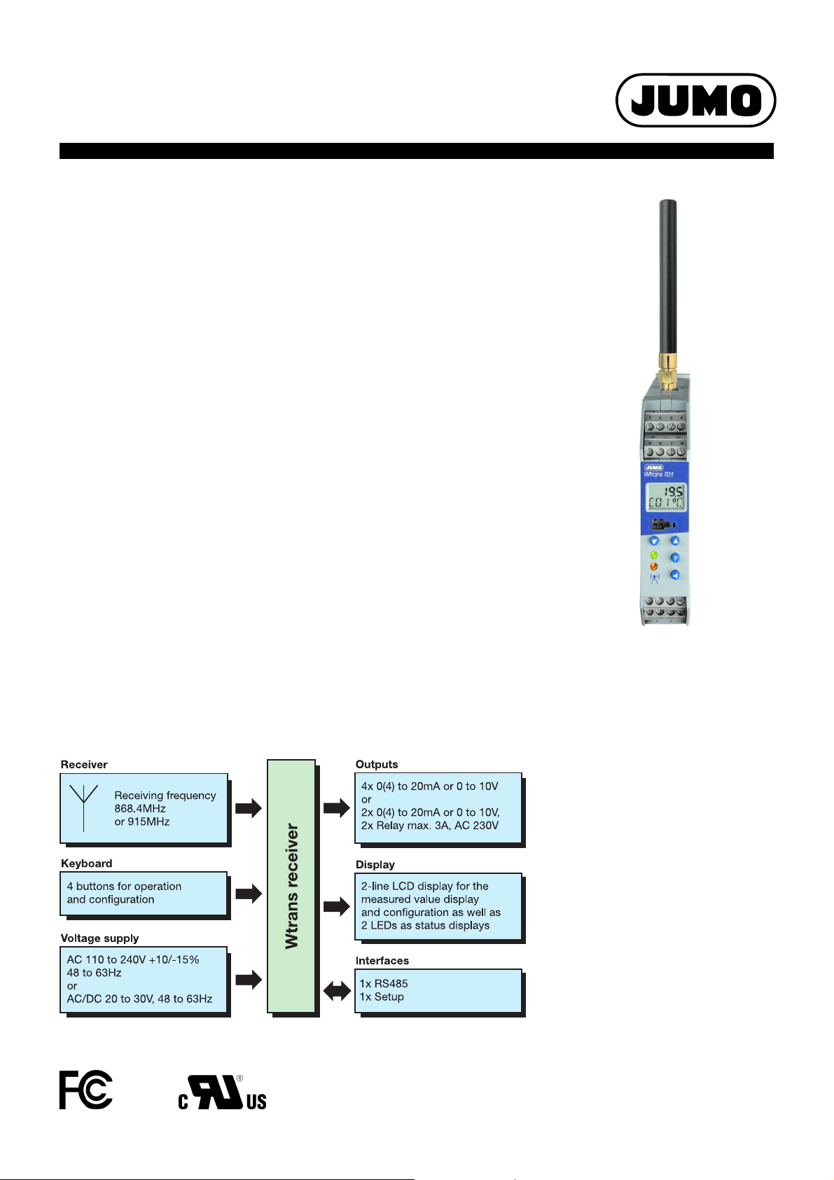
JUMO Wtrans Receiver
with Wireless Data Transmission
k For measuring temperature, pressure, potentiometer, and voltage.
k Interface RS485 with Modbus protocol
k Wireless measured value reception
k No wiring work due to modern wireless technology
k For up to 16 transmitters per receiver
The Wtrans receiver T01 in combination with suitable Wtrans transmitters is used for mobile or
stationary measurements of physical variables. A significant reduction of the installation work is
achieved due to the use of trendsetting wireless technology found in the industrial radio frequency 868.4 MHz or 915 MHz. Cable connections are not required, the radio-based sensor
technology also functions in a rough industrial environment. The supplied lambda/4-antenna
with an impedance of 50 ohm can be screwed on directly or fitted externally. If the antenna wall
holder with a 3 m antenna cable is used then the open air range is 300 m. In the receiver the
received measured values are converted, displayed, and are available as linear current or voltage signals (0(4) to 20 mA, 0 to10 V) and via the digital interface RS485. All receiver outputs are
electrically isolated. The connection to higher-ranking systems (e.g. the plant visualization software JUMO SVS3000 or the Modbus master compatible paperless recorder JUMO LOGOSCREEN nt) is possible via the digital interface with Modbus protocol.
Operation and configuration is possible via the keypad in connection with a 2-line LCD display
or a setup program for greater comfort. Thus, parameters such as filter constants, offset,
alarms, and drag indicator (minimum and maximum value memory) can be separately set for
each channel. For this purpose, a plug is provided on the front for a PC interface with TTL/
RS232 or USB/TTL converter to connect the receiver and the PC. The receiver in the mounting
rail case is intended for fitting on a DIN rail 35 mm × 7.5 mm according to DIN EN 60715. The
screw terminals for the electrical connection are arranged at different levels. The conductor
cross section may not exceed 2.5 mm
2
.
Data Sheet 902931
Basic type 902931/10
Page 1/10
Block diagram
Approvals/approval marks (see "Technical Data")
2012-06-20/00473257
Suitable
Wtrans transmitters
• Wtrans RTD temperature probe
Data sheet 902930
•Wtrans B
Data sheet 707060
•Wtrans p
Data sheet 402060
For further information see page 10/10
Page 2

JUMO GmbH & Co. KG
Delivery address: Mackenrodtstraße 14
36039 Fulda, Germany
Postal address:
36035 Fulda, Germany
Phone: +49 661 6003-0
Fax: +49 661 6003-607
E-mail: mail@jumo.net
Internet: www.jumo.net
JUMO Instrument Co. Ltd.
JUMO House
Temple Bank, Riverway
Harlow, Essex CM20 2DY, UK
Phone: +44 1279 635533
Fax: +44 1279 635262
E-mail: sales@jumo.co.uk
Internet: www.jumo.co.uk
JUMO Process Control, Inc.
8 Technology Boulevard
Canastota, NY 13032, USA
Phone: 315-697-5866
1-800-554-JUMO
Fax: 315-697-5867
E-mail: info.us@jumo.net
Internet: www.jumousa.com
Data Sheet 902931 Page 2/10
Technical data
Input
Number of transmitters Up to 16 transmitters can be received per receiver.
Radio frequency 868.4 MHz (Europe);
Open air range Up to 300 m when using the antenna wall holder with a 3 m antenna cable
Measuring range limits Depending on the set sensor
Configuration Using the keys on the device or the setup program
Unit The units for temperature, pressure, potentiometer, and voltage
Analog outputs
Quantity 4 analog outputs for basic type 902931/10, 2 analog outputs for basic type 902931/30
Output signal:
- Current
- Voltage
Transmission behavior Linear, freely scalable
Burden (at current output) ≤ 500 ohm
Load (at voltage output) ≥ 10 k ohm
Setting time for temperature changes The setting time depends on the transmission interval that is set in the transmitter.
Setting time after switch-on or reset ≤ 5s
Calibration conditions AC 230 V/22 °C (±3 K) or DC 24 V/22 °C (±3 K)
Accuracy ≤ ±0.1 %
Residual ripple ≤ ±0.2 %
Electrical isolation The analog outputs are electrically isolated from each other and the interfaces.
Isolation voltage 50 V
915 MHz (America, Australia, Canada, and New Zealand);
Ten frequencies can be configured in the 915 MHz frequency band.
When installing the antenna directly to the receiver, a reduced range of approx. 40 % must be
taken into account.
are configurable on the device or with the setup program.
Configurable with the keys on the device or the setup program
Load-independent direct current 0 to20 mA or 4 to 20 mA
Direct voltage 0 to 10 V
1
(accuracy includes calibration, linearization, burden influence, load error,
and voltage supply error)
1
Measuring circuit monitoring of the analog outputs
Underrange
- Current output 4 to 20 mA
- Current output 0 to 20 mA
- Voltage output 0to10V
Dropping to 3.8 mA, then jump to the configured signaling
Dropping to -0.1 mA, then jump to the configured signaling
Dropping to -0.1 V, then jump to the configured signaling
Overrange
- Current output 4 to 20 mA
- Current output 0 to 20 mA
- Voltage output 0to10V
Increasing to 20.5 mA, then jump to the configured signaling
Increasing to 20.5 mA, then jump to the configured signaling
Increasing to 10.25 V, then jump to the configured signaling
Probe short-circuit or
Probe/cable break and alarms:
- Current output 4 to 20 mA
Positive signaling: > 21 mA
Negative signaling: < 3.6 mA
- Current output 0 to 20 mA
Positive signaling: > 21 mA
Negative signaling: < -0.1 mA
- Voltage output 0to10V
Positive signaling: > 10.5 V
Negative signaling: < -0.1 V
Output behavior The output behavior (positive or negative signaling) can be configured.
1
All accuracy specifications in % from the measuring range end value of 20 mA or 10 V.
2012-06-20/00473257
Page 3

JUMO GmbH & Co. KG
Delivery address: Mackenrodtstraße 14
36039 Fulda, Germany
Postal address:
36035 Fulda, Germany
Phone: +49 661 6003-0
Fax: +49 661 6003-607
E-mail: mail@jumo.net
Internet: www.jumo.net
JUMO Instrument Co. Ltd.
JUMO House
Temple Bank, Riverway
Harlow, Essex CM20 2DY, UK
Phone: +44 1279 635533
Fax: +44 1279 635262
E-mail: sales@jumo.co.uk
Internet: www.jumo.co.uk
JUMO Process Control, Inc.
8 Technology Boulevard
Canastota, NY 13032, USA
Phone: 315-697-5866
1-800-554-JUMO
Fax: 315-697-5867
E-mail: info.us@jumo.net
Internet: www.jumousa.com
Data Sheet 902931 Page 3/10
Relay outputs
Quantity 2 relay outputs for basic type 902931/30
Relay N/O contact configurable as N/C contact
Switching capacity Up to 3 A at AC 230 V resistive load
Contact life 150,000 operations at 3 A / AC 230 V resistive load
350,000 operations at 1 A / AC 230 V resistive load
310,000 operations at 1 A / AC 230 V and cos phi > 0.7
Electrical isolation Relay to analog outputs and interface; test voltage AC 3700 V (reinforced insulation)
Relay to relay; test voltage AC 2300 V (basic insulation)
Combined operation of mains voltage AC 230 V and SELV or PELV voltage
is not admissible due to the basic insulation between the relays.
Electrical data
Voltage supply AC 110 to 240 V +10/-15 %, 48 to 63 Hz or AC/DC 20 to 30 V, 48 to 63 Hz
Power consumption 12 VA
Electrical connection Screw terminals up to 2.5 mm
2
Electrical safety According to DIN EN 61010, part 1
overvoltage category III,
pollution degree 2,
for installation into a control cabinet according to DIN EN 50178
Electrical isolation The voltage supply is electrically isolated from the analog outputs, relays, and interfaces.
Test voltage AC 3700 V
Environmental influences
Ambient temperature range -20 to +50 °C without condensation (even with close mounting)
Storage temperature range -30 to +70 °C
Temperature influence ≤ ±0.005 %
1
/K; per K deviation from the reference temperature 22 °C (±3 K)
Resistance to climatic conditions Rel. humidity ≤ 85 % without condensation according to DIN EN 60721-3-3 3K3
Vibration resistance Max. 1 g at 10 to 55 Hz according to DIN IEC 60068-2-6
EMC
- Interference emission
- Interference immunity
- Radio frequency spectrum
DIN EN 61326-1
Class A - only for industrial use -
Industrial requirements
ETSI EN 300 220-1 and ETSI EN 300 220-2
Case
Material Polyamide
Flammability class UL 94 V-2
Dimensions
With antenna screw connection (W × H × D) 22.5 mm × 115.0 mm × 117.8 mm
Installation DIN rail 35 mm × 7.5 mm according to EN 60715
Protection type IP20 according to DIN EN 60529
Installation position Vertical
Weight Approx. 200 g
Interfaces
1
All accuracy specifications in % from the measuring range end value of 20 mA or 10 V.
2012-06-20/00473257
Page 4

JUMO GmbH & Co. KG
Delivery address: Mackenrodtstraße 14
36039 Fulda, Germany
Postal address:
36035 Fulda, Germany
Phone: +49 661 6003-0
Fax: +49 661 6003-607
E-mail: mail@jumo.net
Internet: www.jumo.net
JUMO Instrument Co. Ltd.
JUMO House
Temple Bank, Riverway
Harlow, Essex CM20 2DY, UK
Phone: +44 1279 635533
Fax: +44 1279 635262
E-mail: sales@jumo.co.uk
Internet: www.jumo.co.uk
JUMO Process Control, Inc.
8 Technology Boulevard
Canastota, NY 13032, USA
Phone: 315-697-5866
1-800-554-JUMO
Fax: 315-697-5867
E-mail: info.us@jumo.net
Internet: www.jumousa.com
Setup interface
- Baud rate
- PC interface
9600
With TTL/RS232 or with USB/TTL converter
RS485 interface
- Protocol
- Baud rate
- Device address
- Minimum response time
Modbus
9600, 19200, 38400
1 to 254
0 to 500 ms
LCD display
Top line 4-digit 7-segment display, 4.5 mm high
Bottom line 5-digit 16-segment display, 4.0 mm high
Approvals/approval marks
Approval marks Testing agency Certificates/certification
numbers
c UL us Underwriters Laboratories E201387 UL 61010-1
IC Industry Canada 7472A-WTRANST01
7472A-WTRANST0102
FCC Federal Communications
VT4-WTRANST01
Commission
VT4-WTRANST01-02
Inspection basis Valid for
CAN/CSA-C22.2 No. 61010-1
RSS-210 Issue 7
RSS-210 Issue 8
RSS-GEN Issue 3
RSS-102 Issue 4
FCC Rule Part 15C
FCC Rule Part 15C
Data Sheet 902931 Page 4/10
915 MHz, 230 V,
Basic type 902931/10
915 MHz, 230 V,
Basic type 902931/10
915 MHz, 230 V,
Basic type 902931/10
2012-06-20/00473257
Page 5

JUMO GmbH & Co. KG
Delivery address: Mackenrodtstraße 14
36039 Fulda, Germany
Postal address:
36035 Fulda, Germany
Phone: +49 661 6003-0
Fax: +49 661 6003-607
E-mail: mail@jumo.net
Internet: www.jumo.net
JUMO Instrument Co. Ltd.
JUMO House
Temple Bank, Riverway
Harlow, Essex CM20 2DY, UK
Phone: +44 1279 635533
Fax: +44 1279 635262
E-mail: sales@jumo.co.uk
Internet: www.jumo.co.uk
JUMO Process Control, Inc.
8 Technology Boulevard
Canastota, NY 13032, USA
Phone: 315-697-5866
1-800-554-JUMO
Fax: 315-697-5867
E-mail: info.us@jumo.net
Internet: www.jumousa.com
Operation and configuration
1 7 segment LCD display,
4.5 mm, 4 digit
5 Bicolor LED
- Green = malfunction-free operation
- Red flashing = collective alarm
(the collective alarm includes the
radio timeout of transmitters 1 to16,
the limit value monitoring min./max.
of channels C01 to C16, detected
memory errors during power on, and
the low battery signal of transmitters
1 to 16)
2 16 segment LCD display,
4.0 mm, 5 digit
3 Setup interface
4Function keys
6 Yellow short flashing LED
- Receipt control for each
data packet from the transmitter
At the receiver
Operation and configuration of the receiver require four keys located at the front. These have
various functions depending on the menu. The dialog is supported by a 2-line LCD display. Two
LEDs signal various operating statuses. The operation and configuration of the parameters are
organized into three different levels:
- Normal display (display of values and signal quality)
- Commissioning/start-up level (channel linking to transmitter ID)
- Parameter level (editing of configuration parameters)
Each of the two levels can be protected against unauthorized access by a code.
Data Sheet 902931 Page 5/10
Setup program
Configuration via the setup program is more
comfortable than using the receiver keypad.
The configuration data can be archived on
data storage devices and printed.
All configurable parameters are described in
this operating manual.
The setup program can be used to overwrite
changed parameters with the factory settings
at any time.
The connection between receiver and PC is
established via a PC interface (USB/TTL or
TTL/RS232 converter).
OnlineChart (optional)
The OnlineChart extension can graphically
display and save the measured values of eight
analog and four binary channels.
Customer specific linearization
For transmitters with potentiometer or voltage
input the user can define up to four customerspecific linearizations (value pairs or polynomial formula).
2012-06-20/00473257
Page 6

JUMO GmbH & Co. KG
Delivery address: Mackenrodtstraße 14
36039 Fulda, Germany
Postal address:
36035 Fulda, Germany
Phone: +49 661 6003-0
Fax: +49 661 6003-607
E-mail: mail@jumo.net
Internet: www.jumo.net
JUMO Instrument Co. Ltd.
JUMO House
Temple Bank, Riverway
Harlow, Essex CM20 2DY, UK
Phone: +44 1279 635533
Fax: +44 1279 635262
E-mail: sales@jumo.co.uk
Internet: www.jumo.co.uk
JUMO Process Control, Inc.
8 Technology Boulevard
Canastota, NY 13032, USA
Phone: 315-697-5866
1-800-554-JUMO
Fax: 315-697-5867
E-mail: info.us@jumo.net
Internet: www.jumousa.com
Assignment of transmitters to the receiver
(linking)
A receiver can display and process data from up to 16 transmitters. Each transmitter must be
linked with the receiver. Three linking methods are available:
- On the device using a list of received, non-linked transmitter IDs or by directly entering the
transmitter ID
- Using the setup program, and
- Via the RS485 interface by Modbus commands.
The list of received, non-linked transmitter IDs is automatically saved by the receiver. The transmitter IDs are automatically detected in this list (max. 25 entries); then they are entered and deleted. The transmitter ID can be directly entered at the device or with the setup program. The
transmitter IDs can also be set from a Modbus master (e.g. PLC) via the RS485 interface at any
time.
Open air range
The open air range is 300 m. To achieve this max. receiving quality and to achieve an optimum
adaptation of the lambda/4-antenna, use the antenna wall holder with the 3 m antenna cable
(available in the accessories). When installing the antenna directly on the receiver, a reduced
range of approx. 40 % must be taken into account. The transmission range may be additionally
reduced by buildings, concrete ceilings, walls, and other structural works.
Data Sheet 902931 Page 6/10
2012-06-20/00473257
Page 7

JUMO GmbH & Co. KG
Delivery address: Mackenrodtstraße 14
36039 Fulda, Germany
Postal address:
36035 Fulda, Germany
Phone: +49 661 6003-0
Fax: +49 661 6003-607
E-mail: mail@jumo.net
Internet: www.jumo.net
JUMO Instrument Co. Ltd.
JUMO House
Temple Bank, Riverway
Harlow, Essex CM20 2DY, UK
Phone: +44 1279 635533
Fax: +44 1279 635262
E-mail: sales@jumo.co.uk
Internet: www.jumo.co.uk
JUMO Process Control, Inc.
8 Technology Boulevard
Canastota, NY 13032, USA
Phone: 315-697-5866
1-800-554-JUMO
Fax: 315-697-5867
E-mail: info.us@jumo.net
Internet: www.jumousa.com
Dimensions
1234
5678
9 101112
L1N1516
(L+) (L-)
Data Sheet 902931 Page 7/10
Basic type 902931/10 and 902931/30
2012-06-20/00473257
Page 8

Data Sheet 902931 Page 8/10
JUMO GmbH & Co. KG
Delivery address: Mackenrodtstraße 14
36039 Fulda, Germany
Postal address:
36035 Fulda, Germany
Phone: +49 661 6003-0
Fax: +49 661 6003-607
E-mail: mail@jumo.net
Internet: www.jumo.net
JUMO Instrument Co. Ltd.
JUMO House
Temple Bank, Riverway
Harlow, Essex CM20 2DY, UK
Phone: +44 1279 635533
Fax: +44 1279 635262
E-mail: sales@jumo.co.uk
Internet: www.jumo.co.uk
JUMO Process Control, Inc.
8 Technology Boulevard
Canastota, NY 13032, USA
Phone: 315-697-5866
1-800-554-JUMO
Fax: 315-697-5867
E-mail: info.us@jumo.net
Internet: www.jumousa.com
L1
(L+)N(L-)
L1
(L+)
N
(L-)
12
–
+
34
–
+
56
–
+
56
–
+
21
43
10911
Connection diagram
The connection diagram in the data sheet provides preliminary information about the connection possibilities. Only use the installation instructions or the operating manual for the electrical connection. The knowledge and the correct technical execution of the safety information/instructions contained in these documents are mandatory for installation, electrical connection, and commissioning/start-up as well as for safety during
operation.
Voltage supply
Connection for Terminal assignment
Voltage supply
according to nameplate:
L1 and N at AC 110 to 240 V
L+ and L- at AC/DC 20 to 30 V
Outputs
Basic type 902931/10 Analog output 1 Analog output 2 Analog output 3 Analog output 4
Current 0(4) to 20 mA
or voltage 0 to 10 V
Basic type 902931/30 Relay output 1 Relay output 2 Analog output 3 Analog output 4
Current 0(4) to 20 mA
or voltage 0 to 10 V
Relay
N/O contact,
configurable as an N/C
Digital interface
RS485 9 TxD+/RxD+
10 GND
11 TxD-/RxD-
Transmit/receive data +
Ground
Transmit/receive data -
2012-06-20/00473257
Page 9

Data Sheet 902931 Page 9/10
JUMO GmbH & Co. KG
Delivery address: Mackenrodtstraße 14
36039 Fulda, Germany
Postal address:
36035 Fulda, Germany
Phone: +49 661 6003-0
Fax: +49 661 6003-607
E-mail: mail@jumo.net
Internet: www.jumo.net
JUMO Instrument Co. Ltd.
JUMO House
Temple Bank, Riverway
Harlow, Essex CM20 2DY, UK
Phone: +44 1279 635533
Fax: +44 1279 635262
E-mail: sales@jumo.co.uk
Internet: www.jumo.co.uk
JUMO Process Control, Inc.
8 Technology Boulevard
Canastota, NY 13032, USA
Phone: 315-697-5866
1-800-554-JUMO
Fax: 315-697-5867
E-mail: info.us@jumo.net
Internet: www.jumousa.com
Order details: JUMO Wtrans receiver T01
(1) Basic type
Wtrans receiver T01.EC1
with wireless value transmission,
902931/10
902931/30
x x 8 Standard with factory settings
x x 9 Customer-specific configuration (specifications in plain text)
x x 10 868.4 MHz (Europe)
x 20 915 MHz (America, Australia, Canada, and New Zealand) (not in connection with AC/DC 20 to 30 V)
x x 23 AC 110 to 240 V +10/-15 %, 48 to 63 Hz
x x 25 AC/DC 20 to 30 V, 48 to 63 Hz
x x 000 None
C rail case, protection type IP20,
4x analog outputs 0(4) to 20 mA or 0 to10 V,
interface RS485 with Modbus protocol
Wtrans receiver T01.EC3
with wireless value transmission,
C rail case, protection type IP20,
2x analog outputs 0(4) to 20 mA or 0 to10 V
and 2x relay outputs AC 230 V/5 A potential free,
interface RS485 with Modbus protocol
(2) Version
(3) Radio frequency
In the 915 MHz frequency band, ten frequencies are configurable
(4) Voltage supply
(5) Extra codes
(1) (2) (3) (4) (5)
Order code ---/
Order example 902931/10 - 8 - 10 - 23 / 000
2012-06-20/00473257
Page 10

JUMO GmbH & Co. KG
Delivery address: Mackenrodtstraße 14
36039 Fulda, Germany
Postal address:
36035 Fulda, Germany
Phone: +49 661 6003-0
Fax: +49 661 6003-607
E-mail: mail@jumo.net
Internet: www.jumo.net
JUMO Instrument Co. Ltd.
JUMO House
Temple Bank, Riverway
Harlow, Essex CM20 2DY, UK
Phone: +44 1279 635533
Fax: +44 1279 635262
E-mail: sales@jumo.co.uk
Internet: www.jumo.co.uk
JUMO Process Control, Inc.
8 Technology Boulevard
Canastota, NY 13032, USA
Phone: 315-697-5866
1-800-554-JUMO
Fax: 315-697-5867
E-mail: info.us@jumo.net
Internet: www.jumousa.com
Scope of delivery
1 device in the ordered version
1 lambda/4-antenna, impedance 50 ohm, 868.4 MHz, T
1 lambda/4-antenna, impedance 50 ohm, 915 MHz, T
1 operating manual B 902931.0
max.
max.
Data Sheet 902931 Page 10/10
125 °C or
125 °C
Accessories
Part no.
Setup program on CD-ROM, multilingual 00488887
Setup program including OnlineChart on CD-ROM, multilingual 00549067
OnlineChart activation 00549188
Additional lambda/4-antenna, impedance 50 ohm, 868.4 MHz, T
Additional lambda/4 antenna, impedance 50 ohm, 915 MHz, T
Antenna wall holder with antipole for lambda/4-antenna 00482648
Lambda/4-antenna with waterproof line permanently connected, length 10 m, 868.4 MHz, T
Lambda/4-antenna with waterproof line permanently connected, length 20 m, 868.4 MHz, T
Antenna cable, length 3 m, impedance 50 ohm with preconfigured screw-type connection, T
Antenna cable, length 5 m, impedance 50 ohm with preconfigured screw-type connection, T
Antenna cable, length 10 m, impedance 50 ohm with preconfigured screw-type connection, T
Antenna cable, length 10 m, impedance 50 ohm with preconfigured screw-type connection, T
PC interface with USB/TTL converter, adapter (socket) and adapter (pins) 00456352
125 °C 00503151
max.
125 °C 00503152
max.
125 °C 00523293
max.
. 125 °C 00523294
max
85 °C 00482646
max.
. 85 °C 00490066
max
. 85 °C 00490068
max
. 125 °C 00511870
max
PC interface with TTL/RS232 converter and adapter (socket) 00350260
Power adapter for interface converter (serial) 00365933
Interface converter RS232 to RS485 external (serial) 00376969
Interface card 2“ RS485 Moxa CP-132i internal 00397804
Plant visualization software JUMO SVS3000 (data sheet 700755) Paperless recorder JUMO LOGOSCREEN nt (data sheet 706581) -
JUMO Wtrans device series
JUMO Wtrans receiver
Receiver (voltage supply AC 110 to 240 V
or AC/DC20to30V)
Type T01.EC1
Type T01.EC3
JUMO Wtrans transmitter
Type T01.G1
Type T02.G1
Type T03.G1 Ex
4x analog outputs
2x analog outputs and 2x relay outputs
Food insertion RTD temperature probe
(for receivers as of software version 01.01)
Ambient temperature for the case -30 to +85 °C
Ambient temperature for the case: -25 to +125 °C
Ambient temperature for the case: -30 to +85 °C
JUMO Wtrans transmitter
Type T01.G1
Type T02.G1
Type T03.G1 Ex
Mineral-insulated RTD temperature probe with bendable protection
tube
(for receivers as of software version 01.01)
Ambient temperature for the case -30 to +85 °C
Ambient temperature for the case: -25 to +125 °C
Ambient temperature for the case: -30 to +85 °C
JUMO Wtrans transmitter
With M12 × 1 plug connection for RTD temperature probes
(for receivers as of software version 01.01)
Type T01.G2
Type T02.G2
JUMO Wtrans transmitter
Ambient temperature for the case: -30 to +85 °C
Ambient temperature for the case: -25 to +125 °C
With M12 × 1 plug connection and RTD temperature probe
with PTFE connecting cable
(for receivers as of software version 01.01)
Type T03.G2 Ex
Ambient temperature for the case: -30 to +85 °C
JUMO Wtrans B Programmable head transducer with wireless data transmission
(for receivers as of software version 03.01)
JUMO Wtrans p Pressure transmitter with wireless data transmission
(for receivers as of software version 04.01)
Data sheet
902931
902930
902930
902930
902930
707060
402060
Stock versions
(1) (2) (3) (4) (5) Part no.
902931/10 - 8 - 10 - 23 / 000 00543004
902931/10 - 8 - 20 - 23 / 000 00543032
902931/10 - 8 - 10 - 25 / 000 00543005
902931/30 - 8 - 10 - 23 / 000 00543006
902931/30 - 8 - 10 - 25 / 000 00543007
2012-06-20/00473257
 Loading...