

Page 1
JUMO Dtrans T100
Screw-in RTD temperature probe
with transmitter
B 902815.0
Operating Instructions
2013-06-05/00495568
Page 2

Page 3

Contents
1 Introduction ............................................................... 4
2 Identifying the device version .................................. 5
2.1 Type designation .......................................................................................... 5
2.2 Scope of delivery .......................................................................................... 7
2.3 Accessories for programmable 2-wire transmitter ................................... 7
3 Installation ................................................................. 8
3.1 Connection diagram .................................................................................... 8
3.2 Connection example with power supply unit ............................................ 9
3.3 Connection example with supply isolator .................................................. 9
4 Setup program ......................................................... 10
4.1 Configurable parameters ........................................................................... 11
4.2 Software requirements .............................................................................. 12
4.3 Important information about Windows user administration .................. 12
4.4 Fine calibration ........................................................................................... 12
4.5 Connection arrangement ........................................................................... 13
5 Dimensions .............................................................. 15
5.1 Basic types .................................................................................................. 15
5.2 Process connection PA .............................................................................. 16
6 Technical data .......................................................... 19
Page 4

1 Introduction
The screw-in RTD temperature probe, which has a compact design,
consists of a protection tube with an integrated temperature sensor,
a process connection, and an attached housing for the transmitter
electronics. The built-in programmable 2-wire transmitter converts
the resistance value into a current signal.
The screw-in RTD temperature probe with programmable 2-wire
transmitter is used for measuring temperatures from -50 to +150 °C
(-58 to +302 °F), with an extension up to 260 °C (500 °F).
The range, fine calibration, measuring circuit monitoring etc. can all
be configured through the setup program.
The 4 to 20 mA or (reversed) 20 to 4 mA output signal that is
provided is linear with temperature. The instrument is designed for
industrial application and complies with the European standards for
assuring electromagnetic compatibility (EMC).
The transmitter must be protected from temperatures above
85 °C!
Product with an integrated transmitter is not intended for
export to the USA!
4
Page 5
2 Identifying the device version
2.1 Type designation
Order details: JUMO Dtrans T100
Screw-in RTD temperature probe with transmitter
- Product with an integrated transmitter is not intended for
export to the USA! -
(1) Basic type
902815/20 Screw-in RTD temperature probe
with programmable transmitter,
connection: M12 × 1 machine connector,
parts in contact with the medium
electrolytically polished;
surface roughness Ra ≤ 0.8 μm
902815/21 Screw-in RTD temperature probe
with programmable transmitter,
connection: M12 × 1 machine connector,
high-temperature version with extension,
parts in contact with the medium
electrolytically polished;
surface roughness Ra ≤ 0.8 μm
(2) Operating temperature in °C
x 370 -50 to +150 °C (max. transmitter temperature 85 °C)
x 386 -50 to +260 °C (max. transmitter temperature 85 °C)
(3) Measuring insert
x x 1013 1× Pt1000 in 4-wire circuit
(4) Tolerance class according to EN 60751
x x 2 Class A
(5) Protection tube diameter D in mm
xx 6 Ø6mm
(6) Fitting length EL in mm (EL 50 to 500)
x x 50 50 mm
x x 100 100 mm
x x 150 150 mm
x x 200 200 mm
x x ... Please specify in plain text (50 mm steps)
5
Page 6

2 Identifying the device version
(7) Process connection (PA)
xx 000 None
x x 103 G 3/8 (3/8" pipe) thread
x x 104 G 1/2 (1/2" pipe) thread
x x 380 G 1/2 (1/2" pipe) thread with CIP-compliant conical seal
with EHEDG certification
x x 601 Taper nipple with cap nut DN 10 DIN 11851 (milk pipe fitting)
x x 604 Taper nipple with cap nut DN 25 DIN 11851 (milk pipe fitting)
x x 605 Taper nipple with cap nut DN 32 DIN 11851 (milk pipe fitting)
x x 611 Clamping nipple (clamp) DN 10/20 according to DIN 32676
x x 613 Clamping nipple (clamp) DN 25/40 (1"/1.5") according to DIN 32676
x x 616 Clamping nipple (clamp) DN 50 (2") according to DIN 32676
x x 617 Clamping nipple (clamp) 2.5" similar according to DIN 32676
x x 681 Weld-in ball socket with clamping thread
x x 682 Weld-in socket with CIP-compliant conical seal
x x 684 Varivent connection DN 15/10 with EHEDG certification
x x 685 Varivent connection DN 32/25 with EHEDG certification
x x 686 Varivent connection DN 50/40 with EHEDG certification
x x 840 Ball weld-in pocket (material 316 Ti)
x x 997 JUMO PEKA with EHEDG certification
(8) Protection tube material
x x 24 Stainless steel 316 L (mat. ref. 1.4404 or 1.4435)
x x 26 Stainless steel 316 Ti (mat. ref. 1.4571) (upon request)
(9) Extra codes
xx 000 None
x x 100 Customer-specific configuration (specifications in plain text)
x x 310 Protection tube stepped down from 6 mm dia. to 3.3 mm dia.
x x 810 Weld-in socket (only for process connection 380)
(1) (2) (3) (4) (5) (6) (7) (8) (9)
Order code - - - - - - - / ,...
Order example 902815/20 - 370 - 1013 - 2 - 6 - 100 - 104 - 24 / 000
a
a
List extra codes in sequence, separated by commas.
6
Page 7

2 Identifying the device version
2.2 Scope of delivery
- 1 Operating Instructions B 902815.0
2.3 Accessories for programmable 2-wire transmitter
- Setup program on CD-ROM, multilingual,
part no. 00485016
- Configuration cable,
4-pole, with plug and socket M12 × 1
and RJ-45 Western plug,
part no. 00484692
- PVC connecting cable,
4-pole with M12 × 1 socket, length 2 meters,
part no. 00404585
- 5-pole contact box M12 × 1, straight,
without connecting cable to be patched by the customer,
part no. 00419130
- 5-pole contact box M12 × 1, angled,
without connecting cable to be patched by the customer,
part no. 00419133
- PC interface with USB/TTL converter and USB cable,
part no. 00456352
- Transmitter supply units 1-way and 4-way (data sheet 707500)
- Ex-i power supply / input isolating amplifier for electrical isolation
of standard signals and voltage supply
for 2-wire transmitter (data sheet 707530)
7
Page 8
3 Installation
V
+
-
1 3
V+ V-
2 4
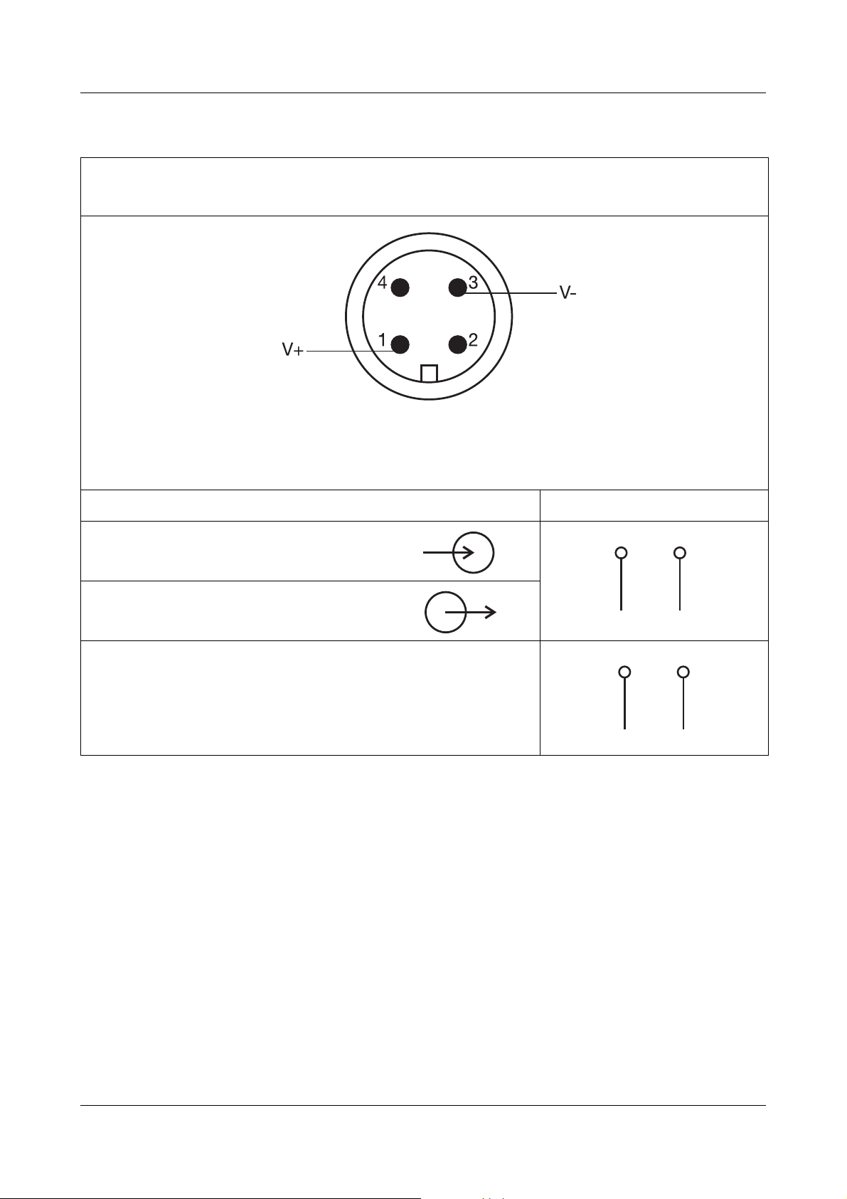
3.1 Connection diagram
M12 × 1 machine connector, 4-pole
according to IEC 60947-5-2
Warning
Do not make any connections to pins 2 and 4!
Electrical connection Pin
Voltage supply
8to35VDC
Current output
4to20mA
Setup communication
via special configuration cable
(for configuration only,
continuous operation is not permissible)
Caution
After the machine connector has been plugged in correctly,
care must be taken that the prescribed voltage supply is
applied and the pins are assigned correctly during
connection. If this is not observed, the device will be
destroyed.
8
Page 9

3 Installation
3.2 Connection example with power supply unit
3.3 Connection example with supply isolator
9
Page 10

4 Setup program
Configuration from a PC
The setup program is available for configuring the programmable 2wire transmitter from a PC. The connection is made using a special
configuration cable with a M12 × 1 machine connector and M12 × 1
socket, and a RJ-45 Western plug. In addition, you will also need the
PVC connecting cable, 2 meters long. The PC interface with USB/TTL
converter and USB cable is needed for connecting up to a PC (see
accessories for the programmable 2-wire transmitter).
In order to configure the 2-wire transmitter, it must be
connected to the voltage supply.
If no power supply unit or supply isolator is available, the
transmitter can be configured using a 9 V battery as a power
source.
10
Page 11

4 Setup program
4.1 Configurable parameters
Setup
level
Hardware Device type - Meas. point
ID
Measuring
range
°C or °F,
configurable
Analog
output
Further
Parameter Value range Factory
TAG number - -
Offset
Range start
Range end
Reversion of the
output
Signal on probe
break or shortcircuit
Filter time constant
-50
+150 °C
or +260 °C
with extension
4to20mA/
20 to 4 mA
<3.8 mA/>21 mA
0 s/ ... / ... 125 s
setting
0.0 °C
0.0 °C
100.0 °C
4to20mA
>21 mA
0.1 s
parameters
Unit
°C/°F
°C
11
Page 12

4 Setup program
4.2 Software requirements
- Microsoft Windows XP or higher
4.3 Important information about Windows user administration
If more than one user is administered by the computer, then the
user who is logged in should be the one who will subsequently be
working with the program. The user must have administrator rights
during the installation of the software. After installation, the rights
can be restricted again. If this is disregarded, it is not possible to
ensure a correct and complete installation.
4.4 Fine calibration
Fine calibration means adjustment of the output signal. Fine
calibration is carried out with the aid of the setup program. Using
the setup program, the 4 mA value (zero) and 20 mA value (full
scale) can be calibrated separately.
12
Page 13

4 Setup program
4.5 Connection arrangement
Use
- The PC interface with USB/TTL converter is only designed for
service use over a limited period, such as the transfer of setup
data.
- It links JUMO devices to a PC through an electrically isolated
connection. The RJ-45 Western plug is specially adapted to
JUMO devices, and is not suitable for third-party equipment.
Do not confuse the RJ-45 socket with an ISDN or network
connection.
Make the connections for the setup program as described below:
1. First connect the USB type A plug (a) to the PC/laptop and then
connect the USB type B plug (b) to the PC interface with USB/
TTL converter (c).
This ensure a safe grounding on the PC/laptop side.
2. Connect the RJ-45 Western plug (d) of the configuration cable
(e) to the PC interface with USB/TTL converter (c) and the
M12 × 1 socket (f) to the JUMO Dtrans T100 (g).
3. Connect the M12 × 1 socket (i) of the PVC connecting cable (j)
to the M12 × 1 plug (h) of the configuration cable (e).
4. Connect the 8 to 35 V DC voltage supply to the PVC
connecting cable (j).
Remove the modular cable (not required for this setup,
therefore not shown in the diagram) of the PC interface with
USB/TTL converter, including two adapters (socket and
plug) – will be needed for other devices.
13
Page 14

4 Setup program
PC/laptop connection
(setup program
Part no. 00485016)
white
black
brown (+) PIN 1
blue (-) PIN 3
approx. 600
PC interface with USB/TTL converter
Part no. 00456352
(with USB cable)
USB type A plug
USB type B plug
RJ-45 Western plug
M12 socket
Configuration cable
Part no. 00484692
JUMO Dtrans T100
M12 socket
M12 plug
PVC 4-pole connecting cable
Part no. 00404585
8—35 VDC
(a)
(b)
(c)
(d)
approx. 2000
approx. 600
(h)
(e)
(f)
( i ) ( j )
(g)
Diagram 1: Connection arrangement for setup with JUMO
Dtrans T100
14
Page 15

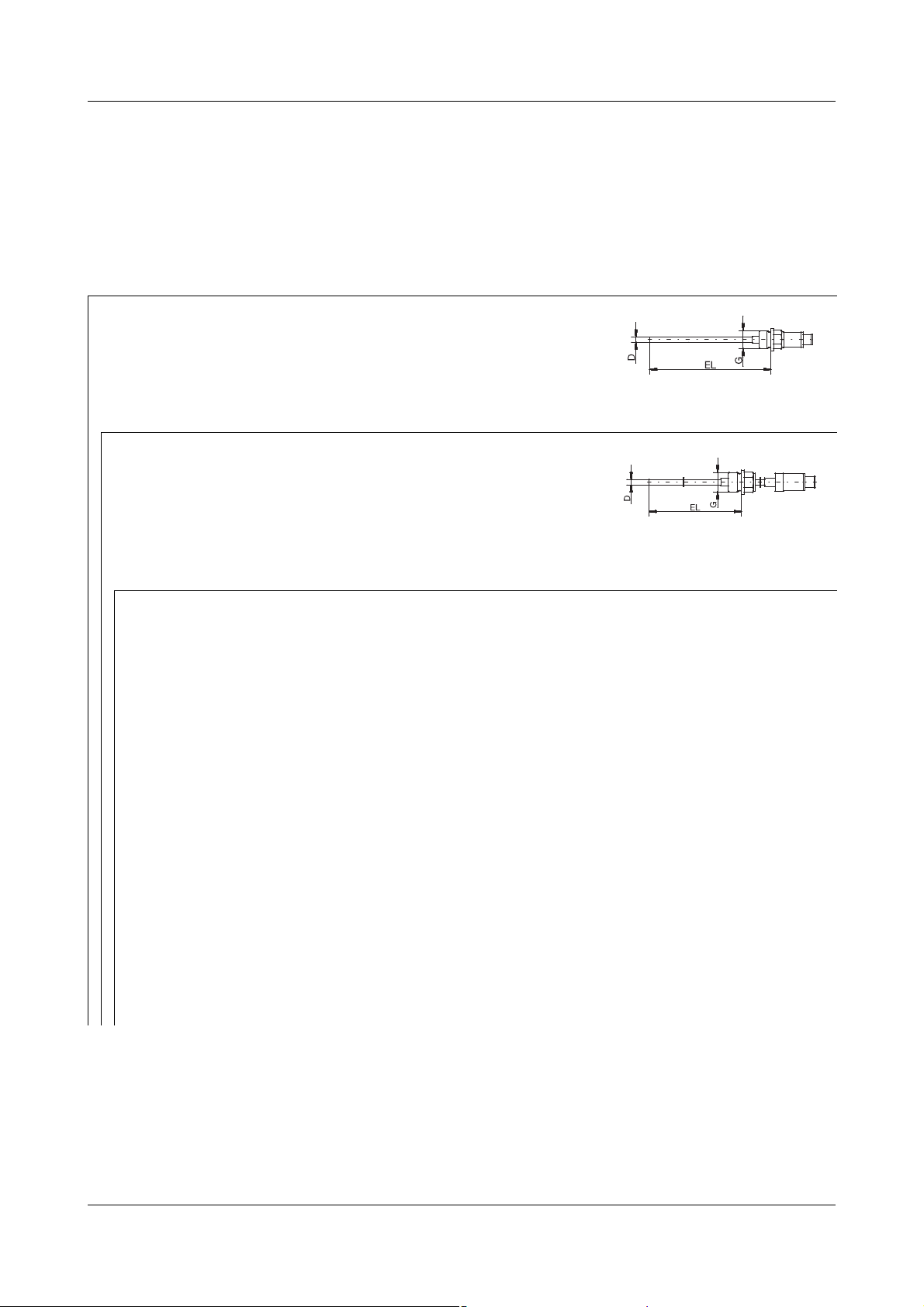
5.1 Basic types
5 Dimensions
Basic type 902815/20... Basic type 902815/21...
with extension
15
Page 16

5 Dimensions
PA G
103 3/8
104 1/2
PA
380
PA DN D1 PA DN D1
- - Ø 25 613 40/1.5" Ø 50.5
611 10/20 Ø 34 616 50/2" Ø 64
613 25/1" Ø 50.5 617 2.5" Ø 77.5
5.2 Process connection PA
Screw fitting Screw fitting with
CIP-compliant conical seal
Clamping nipple
according to DIN 32676 (clamp)
16
Page 17

5 Dimensions
PA
681
PA DN D1 D2 D3 D4 L1 L2
601 10 Ø 22 Ø 18
RD 28 × 1/8
Ø389 18
604 25 Ø 44 Ø 35
RD 52 × 1/6
Ø6313 21
605 32 Ø 50 Ø 41
RD 58 × 1/6
Ø7013 21
28
EL
15
41
D
30Ø
G1/2
18Ø
PA
682
Weld-in ball socket
with clamping nipple
Taper nipple
with cap nut
according to DIN 11851
(milk pipe fitting)
Weld-in socket
with CIP-compliant conical seal
17
Page 18

5 Dimensions
PA DN D1
684 15/10 Ø 31
685 32/25 Ø 50
686 50/40 Ø 68
PA
840
Varivent Clamp Aseptic Weld-in
socket
DN 25/32 DN 25/32/40 DN 40 Ø 55 mm
DN 40-125 DN 50 DN 50 -
-- NKS DN40-
Varivent connection Ball weld-in pocket
JUMO PEKA PA 997
Process connection adapter
see data sheet 409711
18
Page 19

6 Technical data
Input
Measurement input Pt1000 temperature sensor,
EN 60751, class A,
4-wire circuit
Measuring ranges Basic type 902815/20... : -50 to +150 °C
Basic type 902815/21... : -50 to +260 °C
with extension
Tolerance limits 0.15 + 0.002 × |t|, class A
|t| is the numerical value for the
temperature in °C without taking the sign
into account
Response time Water 0.4 m/s protection tube standard
= 5 s; t
t
0.5
= 12 s
0.9
Water 0.4 m/s protection tube stepped
= 2 s; t
t
0.5
0.9
= 5 s
Air 3.0 m/s protection tube standard
= 40 s; t
t
0.5
= 110 s
0.9
Air 3.0 m/s protection tube stepped
= 21 s; t
t
0.5
= 70 s
0.9
Input
Shortest span 10 K
Sampling rate 1 measurement per second
Input filter 1st order digital filter;
filter constant is adjustable
within the range 0 to 125 s
Measuring circuit monitoring
Underrange Linear drop down to 3.8 mA
(according to
NAMUR recommendation 43)
19
Page 20

6 Technical data
Overrange Linear rise up to 20.5 mA
(according to
NAMUR recommendation 43)
Probe short-circuit/
≤ 3.6 mA or ≥ 21.0 mA (configurable)
probe or lead break
Current limiting
≤ 25 mA
on probe short-circuit
or probe break
Output
Output signal Proportional DC current
4to20mA, 20to4mA
Transfer characteristic Linear with temperature
Maximum burden (R
)RB = (Ub - 8 V) devided by 23 mA,
B
max. 600 Ω
Burden error ≤ ±0.02 % per 100 Ω
The % value refers to the range end value
Settling time on a
temperature change
Settling time after a
switch-on or reset
Measuring accuracy
of electronics
Electrical data
Voltage supply
)
(U
b
20 mA
≤ 5s
≤ 5s
0.1 °C or 0.08 %
The % value refers to the measuring span
that was set, the larger value applies
DC 8 to 35 V (pin 1 = +, pin 3 = -),
operation solely with SELV or PELV-
transmitter supply
(according to DIN EN 61140)
Protection rating III (according to DIN 61140)
20
Page 21

6 Technical data
Galvanic isolation Without galvanic isolation between sensor
and output
Leakage resistance > 100 MΩ at DC 100 V measured at room
temperature between connection
terminals and case
Reverse polarity
protection
Voltage supply error ≤ ±0.01 % per V deviation from 24 V
Environmental influences
Ambient temperature
range for head
Storage temperature
range
Ambient
temperature error
Yes
The % value refers to the range end value
20 mA
-30 to +85 °C
-30 to +90 °C
≤ ±(15 ppm/°C × (range end value +200) +
50 ppm/°C × measuring range set) × Δυ
Δυ = deviation of ambient temperature
from the reference temperature
Calibration/reference
conditions
Climatic conditions According to IEC 60068-2-30
Vibration strength According to IEC 60068-2-6
Electromagnetic
compatibility (EMC)
- interference emission
- interference immunity
Protection type IP67 according to DIN EN 60529
DC 24 V at 25 °C ±5 °C (77 °F ±9 °F)
(rel. humidity ≤ 95 % with condensation)
(according to GL characteristics)
DIN EN 61326
class B
industrial requirements
with machine connector plugged in
21
Page 22

6 Technical data
22
Page 23

Page 24

JUMO GmbH & Co. KG JUMO Instrument Co. Ltd. JUMO Process Control, Inc.
Street address:
Moritz-Juchheim-Straße 1
36039 Fulda, Germany
Delivery address:
Mackenrodtstraße 14
36039 Fulda, Germany
Postal address:
36035 Fulda, Germany
Phone: +49 661 6003-0
Fax: +49 661 6003-607
E-mail: mail@jumo.net
Internet: www.jumo.net
JUMO House
Temple Bank, Riverway
Harlow - Essex CM20 2DY, UK
Phone: +44 1279 63 55 33
Fax: +44 1279 63 52 62
E-mail: sales@jumo.co.uk
Internet: www.jumo.co.uk
6733 Myers Road
East Syracuse, NY 13057, USA
Phone: 315-437-5866
1-800-554-5866
Fax: 315-437-5860
E-mail: info.us@jumo.net
Internet: www.jumousa.com
 Loading...