

Page 1
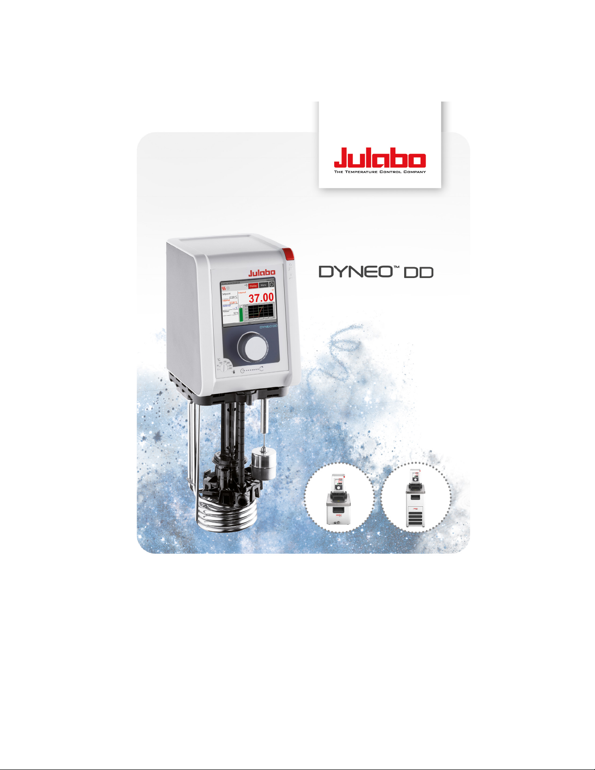
Heating immersion circulators, heating circulators with open
baths, refrigerated circulators
Original operating manual
1.950.1300.en.V04 12/2022
Find Quality Products Online at: [email protected]
www.GlobalTestSupply.com
Page 2

Legal
The content of this operating manual is protected by copyright. Information,
including texts, images, and other contents may not be reproduced, distributed,
transmitted, stored or otherwise used in any form without prior explicit written
consent.
Illustrations in this operating manual are for illustrative purposes and are not
necessarily displayed to scale.
2
Find Quality Products Online at: [email protected]
www.GlobalTestSupply.com
Page 3

1 Foreword ............................................................................................. 7
2 About this manual .............................................................................. 8
2.1 Original JULABO spare parts .......................................................... 8
2.2 Accessories ..................................................................................... 8
2.3 Warnings ......................................................................................... 9
2.4 Symbols used ................................................................................ 10
3 Intended use ..................................................................................... 11
4 Safety ................................................................................................. 12
4.1 Safety instructions ......................................................................... 12
4.2 Safety symbols .............................................................................. 14
4.3 Safety function ............................................................................... 14
5 Product description.......................................................................... 16
5.1 Product overview ........................................................................... 16
5.2 Function description ...................................................................... 16
5.3 Operating and functional elements ............................................... 17
5.4 Interfaces ....................................................................................... 18
5.4.1 Connection of Pt100 temperature sensor ................................ 18
5.4.2 RS232 interface (optional) ....................................................... 19
5.4.3 USB-A interface........................................................................ 19
5.5 Analog interfaces (option) ............................................................. 20
5.5.1 Alarm output ............................................................................. 20
5.5.2 REG/EPROG socket ................................................................ 21
5.5.3 Standby input ........................................................................... 22
5.6 Operating interface ........................................................................ 23
5.6.1 Operation with the central controller ........................................ 24
5.6.2 Softkeys and status icons ........................................................ 24
5.7 Alarm messages ............................................................................ 25
5.8 Operator Messages ....................................................................... 26
5.9 Main menu ..................................................................................... 27
5.9.1 Settings menu .......................................................................... 27
5.9.2 Record data menu .................................................................... 27
5.9.3 Thermodynamics menu ............................................................ 28
5.9.4 Adjust safety menu ................................................................... 28
3
Find Quality Products Online at: [email protected]
www.GlobalTestSupply.com
Page 4

5.9.5 Programmer menu ................................................................... 28
5.9.6 Menu Connect unit ................................................................... 28
5.9.7 Service menu ........................................................................... 29
5.9.8 Install unit menu ....................................................................... 29
5.10 Technical data ............................................................................... 30
5.10.1 Material of parts that come into contact with the medium ........ 32
5.10.2 Technical data for refrigerated circulators ................................ 33
5.10.3 Bath fluids ................................................................................. 39
5.10.4 Hoses ....................................................................................... 40
6 Transport and installation ............................................................... 41
6.1 Transporting the device ................................................................. 41
6.2 Install the device at the operating location .................................... 42
7 Initial operation ................................................................................. 43
7.1 Mounting the circulator .................................................................. 43
7.1.1 Mount heating or refrigerated circulator ................................... 43
7.2 Connect the device to the power supply ....................................... 44
7.2.1 Connect bridge mounted or heating circulator ......................... 44
7.2.2 Connect refrigerated circulator ................................................. 45
7.3 Connecting an external system ..................................................... 46
7.3.1 Connect an external system with screw connections .............. 47
7.3.2 Connect an external system with barbed fittings...................... 49
7.4 Switch on the device and set the language ................................... 50
7.5 Set high temperature safety function ............................................. 50
7.6 Fill device ....................................................................................... 51
7.7 Set up power supply for the refrigerated circulator ....................... 52
7.8 Adjusting the flow of the bath fluid ................................................. 52
7.9 Set chiller mode ............................................................................. 53
7.10 Set limit values .............................................................................. 54
7.10.1 Set temperature warning limits ................................................. 54
7.10.2 Adjusting setpoint limits ............................................................ 54
7.10.3 Adjusting actual value limits ..................................................... 55
7.10.4 Band limit for external control ................................................... 55
7.10.5 Setting band limit ...................................................................... 56
7.11 Connect external temperature sensor ........................................... 56
4
Find Quality Products Online at: [email protected]
www.GlobalTestSupply.com
Page 5

8 Operation ........................................................................................... 57
8.1 Switch on the unit .......................................................................... 57
8.2 Switch off the unit .......................................................................... 57
8.3 Start temperature control application ............................................ 57
8.4 Basic settings ................................................................................ 58
8.4.1 Set language ............................................................................ 58
8.4.2 Set date and time ..................................................................... 58
8.4.3 Activate autostart function ........................................................ 59
8.4.4 Set physical units ..................................................................... 59
8.4.5 Set key tones............................................................................ 59
8.5 Record data ................................................................................... 60
8.5.1 Record measurement data ....................................................... 60
8.5.2 Reading out blackbox data ....................................................... 60
8.5.3 Displaying alarm memory ......................................................... 61
8.6 Thermodynamics ........................................................................... 62
8.6.1 Control parameter .................................................................... 62
8.6.2 Optimizing temperature curves ................................................ 63
8.6.3 Adjust controller ....................................................................... 64
8.6.4 Limit cooling capacity and heating capacity ............................. 64
8.6.5 Adjust pump ............................................................................. 64
8.7 Remote control device ................................................................... 65
8.7.1 Remote control device using USB interface ............................ 65
8.7.2 Set RS232 interface parameters .............................................. 66
8.7.3 Remote control device using RS232 interface ......................... 66
8.7.4 Set EPROG input ..................................................................... 67
8.7.5 Set external setpoint values ..................................................... 67
8.7.6 Set up actuating variable .......................................................... 68
8.7.7 Request device status .............................................................. 68
8.8 Working with the programmer ....................................................... 68
8.8.1 Setting the timer ....................................................................... 69
8.8.2 Creating and editing a temperature control profile ................... 69
8.8.3 Delete temperature control profile ............................................ 70
8.8.4 Set profile timer ........................................................................ 71
8.8.5 Profile series setup ................................................................... 71
8.9 Configure signal outputs................................................................ 72
5
Find Quality Products Online at: [email protected]
www.GlobalTestSupply.com
Page 6

8.9.1 Configure signal outputs of the REG/EPROG plug .................. 72
8.10 Activating stand-by input ............................................................... 73
8.11 Adjusting the temperature sensor (ATC) ....................................... 73
8.11.1 Adjust internal temperature sensor .......................................... 73
8.11.2 Adjust external temperature sensor ......................................... 74
8.12 Device Reset ................................................................................. 75
9 Maintenance ...................................................................................... 76
9.1 Replace detachable power cord .................................................... 76
9.2 Check safety symbols.................................................................... 76
9.3 Check the functionality of high temperature cut-off ....................... 76
9.4 Test the low liquid level safety function ......................................... 77
9.5 Emptying ........................................................................................ 77
9.6 Clean device .................................................................................. 78
9.7 Device storage ............................................................................... 79
9.8 Technical Service .......................................................................... 79
9.9 Warranty ........................................................................................ 80
10 Disposal ............................................................................................. 81
10.1 Device disposal ............................................................................. 81
11 EC Declaration of Conformity ......................................................... 82
12 UK Declaration of Conformity ......................................................... 83
13 Appendix ........................................................................................... 84
13.1 Interface commands ...................................................................... 84
13.1.1 IN commands ........................................................................... 84
13.1.2 OUT commands ....................................................................... 87
13.1.3 Status commands ..................................................................... 89
13.1.4 Status messages ...................................................................... 89
13.2 Alarms and Warnings .................................................................... 90
6
Find Quality Products Online at: [email protected]
www.GlobalTestSupply.com
Page 7

1 Foreword
Foreword
Congratulations!
You have made an excellent choice.
JULABO would like to thank you for the trust you have placed in our company
and products.
This operating manual will help you become acquainted with the use of our
units. Read the operating manual carefully. Keep the operating manual handy at
all times.
7
Find Quality Products Online at: [email protected]
www.GlobalTestSupply.com
Page 8
About this manual
NOTE
2 About this manual
This manual is intended for the equipment specified on the cover page.
Observe the safety instructions!
Read the Safety section of this manual before using the equipment for the
first time.
2.1 Original JULABO spare parts
Hassle-free continuous operation and safety also depend on the quality of the
spare parts used.
Only original JULABO spare parts guarantee the highest possible quality and
safety. Original JULABO spare parts are available directly from JULABO or your
specialist dealer.
Please note that JULABO cannot provide a warranty service if non-original
JULABO spare parts are used.
2.2 Accessories
JULABO offers a wide range of accessories for the devices. Accessories are not
described in this manual.
The complete range of accessories for the devices described in this manual can
be found on our website. Use the Search function on the website.
8
Find Quality Products Online at: [email protected]
www.GlobalTestSupply.com
Page 9
2.3 Warnings
DANGER
WARNING
This signal word designates a danger with a medium level of risk which, if it
CAUTION
NOTE
About this manual
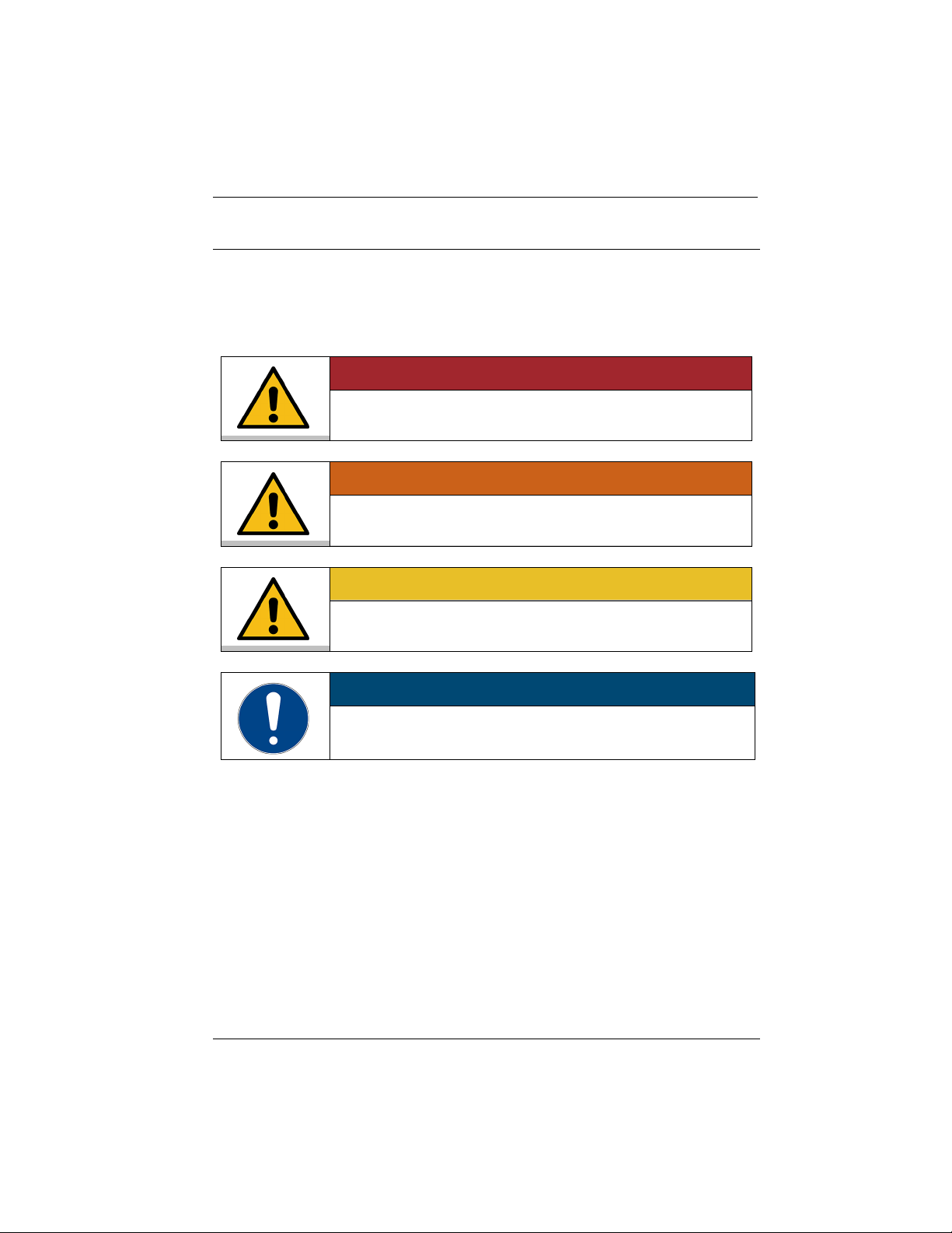
The manual contains warnings to increase safety when using the device.
Warnings must always be observed.
A warning sign displayed in signal color precedes the signal word. The signal
word, highlighted in color, specifies the severity of the hazard.
This signal word designates a danger with a high level of risk which, if it not
prevented, will result in death or serious injuries.
not prevented, may result in death or serious injuries.
This signal word designates a danger with a low level of risk which, if it not
prevented, may result in minor to moderate injuries.
This signal word designates a possibly harmful situation. If it is not avoided,
the system or objects in its vicinity may be damaged.
9
Find Quality Products Online at: [email protected]
www.GlobalTestSupply.com
Page 10

About this manual
2.4 Symbols used
Various symbols are used throughout this manual to aid reading
comprehension. This list describes the symbols used.
Tools needed for the following approach
Prerequisite to be met for the following procedure
1. Numbered action steps
Interim result for individual action steps
Additional note for individual action steps
Final result of a procedure
<> Terms in angle brackets denote control menu
[] Terms in square brackets denote keys, softkeys and buttons
10
Find Quality Products Online at: [email protected]
www.GlobalTestSupply.com
Page 11

3 Intended use
This section defines the purpose of the unit so that the operator can operate the
unit safely and avoid misuse.
JULABO circulators are laboratory devices that are designed for temperature
control applications with liquid media in a bath tank or with a cooling machine.
An external loop circuit can be connected to the pump connectors so that the
temperature of the bath media can be kept constant.
Only use the device if it is in technically perfect condition and only use it in
accordance with its intended use. Be aware of safety issues or hazards and
comply with the operating manual! In particular, always immediately rectify
faults that could impair safety!
The circulators are not suitable for direct temperature control application of
food, other consumables or pharmaceutical or other medical products.
The devices are not suitable for use in an explosive environment.
The devices are not intended for use in living areas. They may cause interference
with radio reception.
Intended use
11
Find Quality Products Online at: [email protected]
www.GlobalTestSupply.com
Page 12

Safety
4 Safety
4.1 Safety instructions
The unit is built in accordance with state of the art technology and recognized
safety regulations. Despite this, its use may pose a risk to life and limb for the
user or third parties.
Therefore, always read and observe the following safety instructions before
using the product.
Hot surfaces!
The following parts and elements may become hot during operation:
– Bath fluid
– Heating element
– Bath lid
– Bath surface
– Connections for external application
Contact may cause severe burns or scalds to hands and arms, face and limbs.
• Keep sufficient distance from hot surfaces and fluids.
• Wear suitable protective gloves.
Electric shock from electrical system!
Touching damaged live parts can cause severe electric shocks and lead to injury
or even death.
• Have damaged insulation and parts of the electrical system immediately
repaired by JULABO service technicians or a qualified specialist workshop
• Immediately replace damaged power cords
• When connected with a mains plug, this mains plug must always be readily
accessible
Refrigerants are harmful to health!
Refrigerants and their vapors are harmful to health. There is a suffocation risk in
enclosed spaces.
• Do not touch or inhale refrigerants.
• Have damage to the refrigerant cycle repaired only by JULABO service
technicians or qualified specialists.
• If refrigerant leaks, stop the device immediately and ventilate the room
thoroughly.
12
Find Quality Products Online at: [email protected]
www.GlobalTestSupply.com
Page 13

Safety
Natural refrigerants are flammable!
The device contains flammable refrigerants. If there is a leak in the refrigerant
cycle, a flammable concentration may form in the air and ignite or explode. This
can result in serious injury or death.
• Use the required minimum room size for operating the device.
• Do not store any potential sources of ignition near the device.
• If refrigerant leaks, stop the device immediately and ventilate the room
thoroughly.
• Have damage to the refrigerant cycle repaired only by JULABO service
technicians or qualified specialists.
• Have maintenance work performed only by JULABO service technicians or
qualified specialists.
Wear personal protective equipment!
Lacking or unsuitable personal protective equipment increases the risk of health
damage and injury.
Personal protective equipment includes, for example:
– Work gloves
– Safety shoes
- Protective clothing
– Breathing protection
- Hearing protection
– Face and eye protection
• Specify and provide personal protective equipment for the respective
application.
• Use only personal protective equipment that is in good condition and
provides effective protection.
• Adapt personal protective equipment to the person, e.g., by size.
Keep safety symbols legible!
Safety symbols on the unit warn of dangers in hazardous areas and are an
important part of the unit’s safety equipment. Missing safety symbols increase
the risk of injury to persons.
• Clean dirty safety symbols.
• Replace damaged and unrecognizable safety symbols immediately.
Maintenance and repair work!
Improper maintenance and repair work jeopardizes operational safety. This can
result in serious injury or death.
• Only carry out work described in this operating manual. Switch off the unit
and disconnect it from the power supply before carrying out any work.
• All other maintenance and repair work may only be carried out by a JULABO
service technician or a qualified specialist workshop.
13
Find Quality Products Online at: [email protected]
www.GlobalTestSupply.com
Page 14
Safety
4.2 Safety symbols
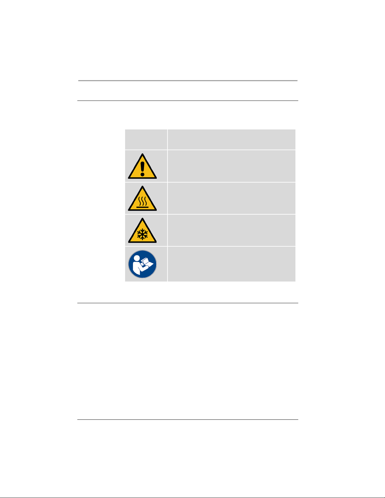
There are safety symbols included with the device, which should be attached to
the device before initial operation.
Safety
symbols
Description
Warning of a danger zone. Note operating manual
Warning about hot surface
Warning of cold surface
Read operating manual before switching on
4.3 Safety function
Technical protective devices provide for safe operation. If a safety function is
triggered, the operator is alerted with a message on the display and an acoustic
signal.
14
Adjustable high temperature cut-off
The high temperature cut-off prevents overheating of the heater.
• If the measured temperature rises above the set protective temperature, an
error message is shown on the display. The pump and heater are switched
off. A restart is required.
Find Quality Products Online at: [email protected]
www.GlobalTestSupply.com
Page 15

Product descr ipti on
Safety
Overheating protection
The overheating protection prevents overheating of the heater.
• The protection mechanism responds when a certain temperature difference
between the working temperature sensor and the safety temperature sensor
is exceeded. A warning message appears on the display. The heating
capacity is limited.
• If the temperature difference persists for longer, an alarm message appears
on the display and the temperature control application is switched off.
Low liquid level protection
A level switch recognizes when the bath fluid fill level in the bath tank is too
low. The device has a two-stage warming system to prevent overheating of the
heater or dry running of the pump.
• The low liquid level warning is triggered when the liquid level in the bath
tank is about half the full level. A warning message appears on the display.
The bath fluid should be topped up.
• The low liquid level alarm is triggered when the float reaches its lower limit
stop. The device switches off the pump and heater. A continuous signal
tone sounds. A warning message appears on the display. A restart is
required.
15
Find Quality Products Online at: [email protected]
www.GlobalTestSupply.com
Page 16
Product description
5 Product description
Product overvi ew
5.1 Product overview
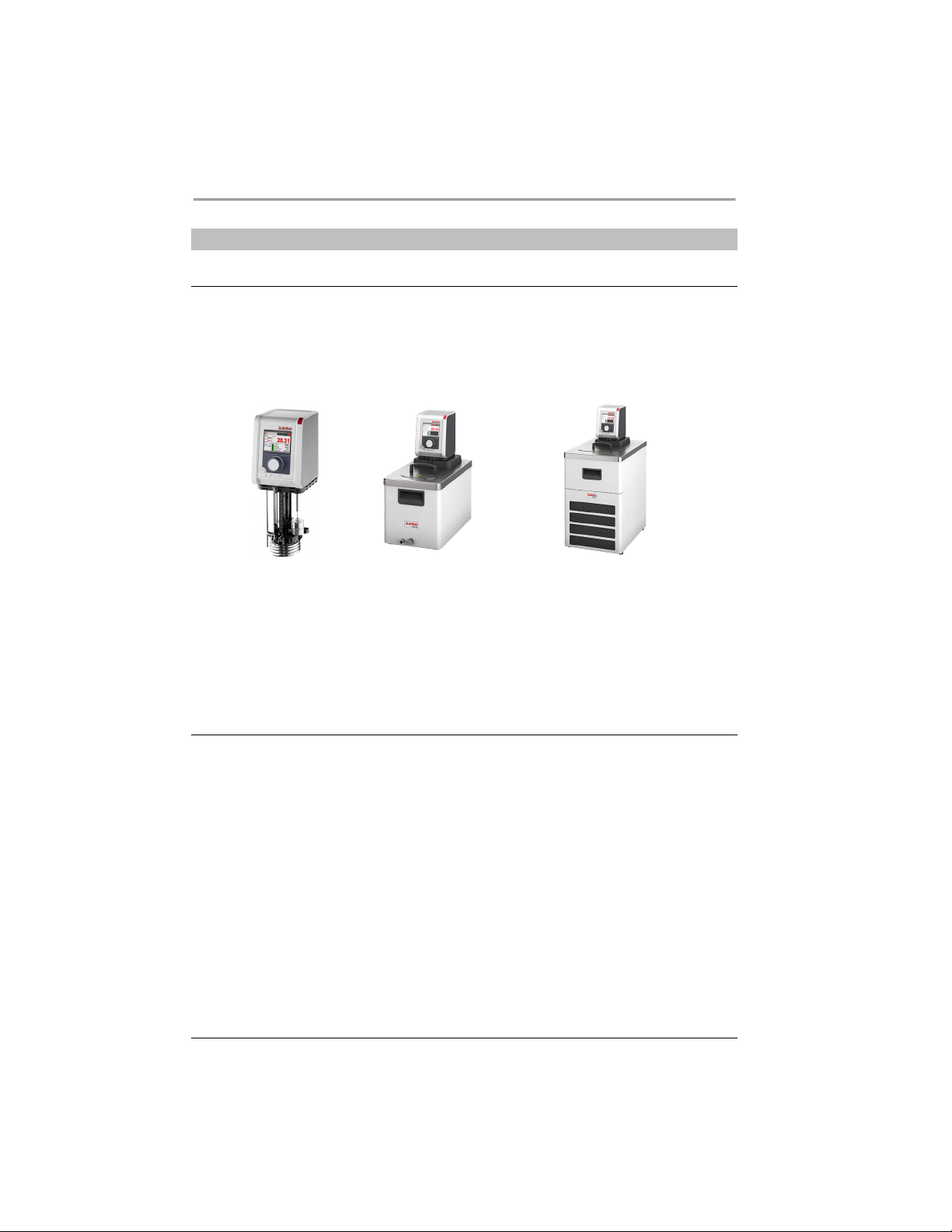
Circulators can be combined with various baths and cooling machines.
Heating immersion
circulator
Heating circulator Refrigerated circulator
DYNEO DD Circulator
Circulator with closed
stainless steel bath tank.
Example: DYNEO DD-BC6 for
temperature control
applications in the bath or
externally
5.2 Function description
This section describes the function of the device.
The circulator can be mounted on any bath tank with a volume up to 50 liters.
The circulators are used for internal and external temperature control, and
depending on the device combination and accessories used can work in a
temperature range between -50°C and +200°C.
When mounted on a bath tank the circulator is a heating circulator, when
combined with a cooling machine it is a refrigerated circulator.
Circulator with cooling
machine. Example:
DYNEO DD-601F for standard
temperature applications
16
Find Quality Products Online at: [email protected]
www.GlobalTestSupply.com
Page 17
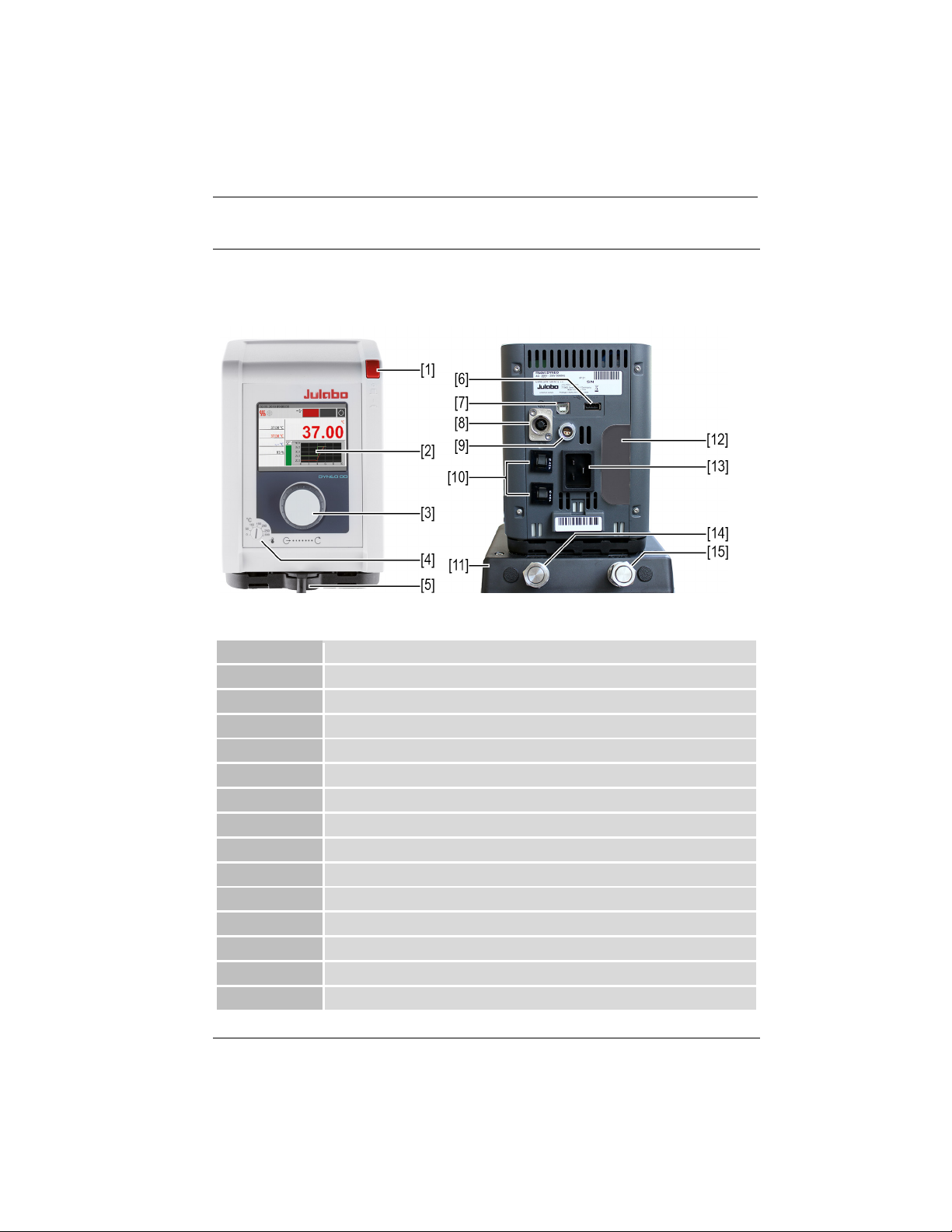
5.3 Operating and functional elements
1
Mains switch
2
Display
3
Central controller
4
High temperature cut-off setting
5
Internal/external flow direction setting
6
USB interface Type A
7
USB interface Type B
8
CAN plug for connection with a cooling machine
9
Interface for external temperature sensor
10
Mains fuse, resettable
11
Assembly frame with pump connections (not for heating immersion circulator)
12
Cover for optional interfaces
13
Mains connection
14
Runback pump connection
15
Supply pump connection
The following figure shows the operating and functional elements and their
position on the unit.
Control and function elements
Product description
17
Find Quality Products Online at: [email protected]
www.GlobalTestSupply.com
Page 18
Product description
5.4 Interfaces
This section describes the electronic interfaces on the device.
For safe operation, the interfaces must be operated according to their
corresponding permissible specifications.
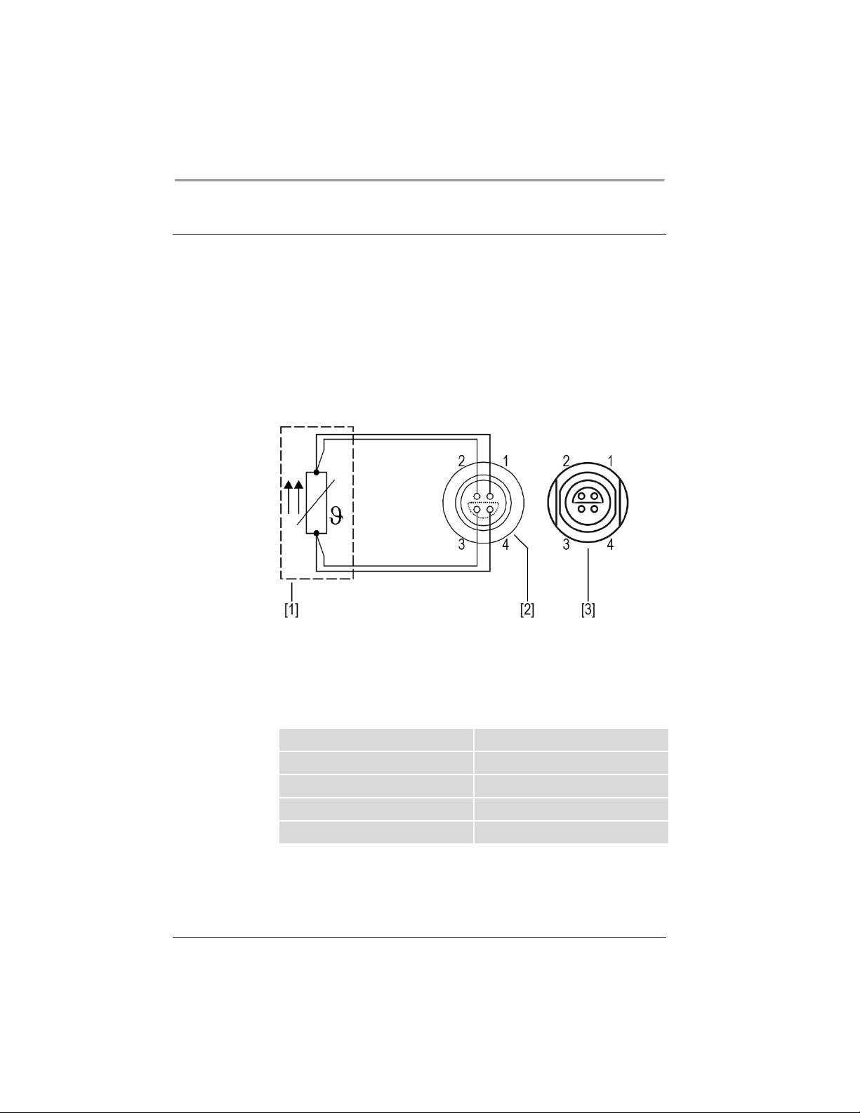
5.4.1 Connection of Pt100 temperature sensor
The plug ext. Pt100 is used to connect an external Pt100 temperature sensor.
The following section describes the wiring of the plug as well as the connection
cable of the temperature sensor.
Connection of a external Pt100 temperature sensor
[1] Temperature sensor Pt100
[2] Plug, view of solder side
[3] Connection socket on device
Pin Signal
1 I+
2 U+
3 U-
4 I-
18
Find Quality Products Online at: [email protected]
www.GlobalTestSupply.com
Page 19
5.4.2 RS232 interface (optional)
RS232 interface factory setting
Stop bit
1
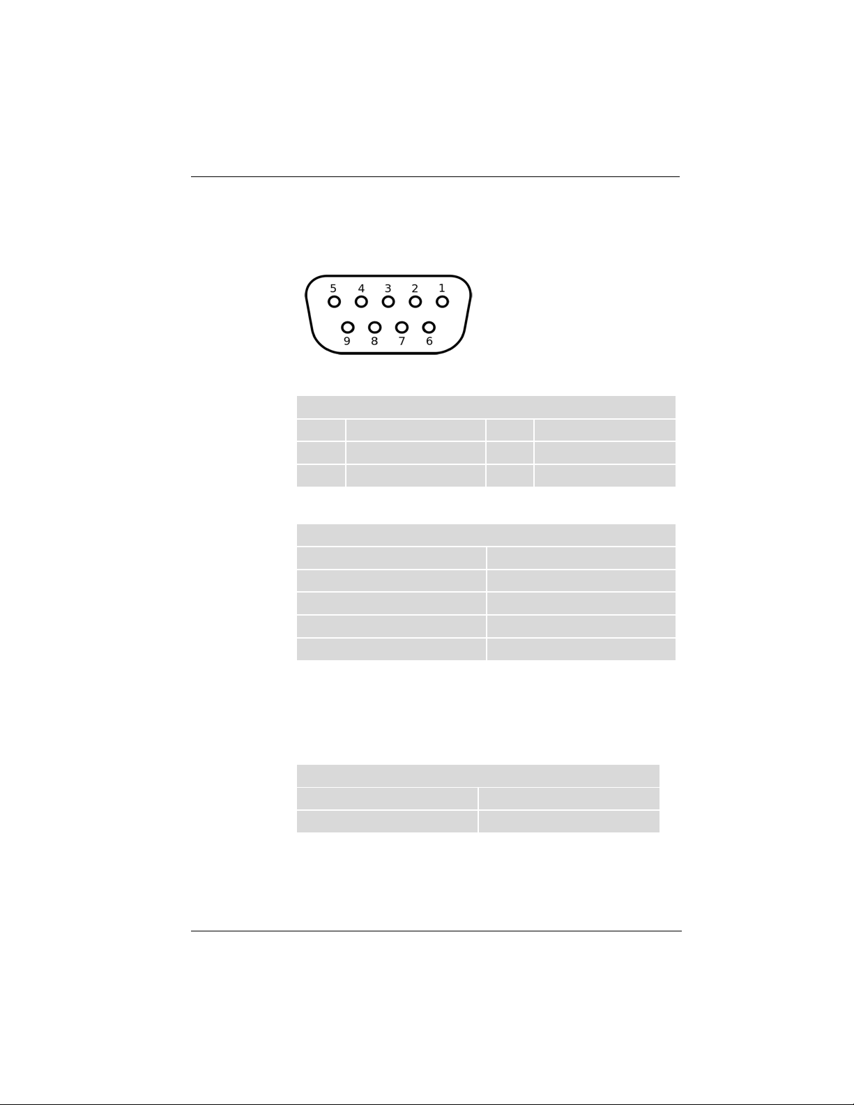
The RS232 interface is a 9-pin D-Sub socket for connecting the device to a PC.
RS232 plug
RS232 interface pin assignment
Pin 2 RxD receive data Pin 7 RTS request to send
Pin 3 TxD transmit data Pin 8 CTS clear to send
Pin 5 0 V signal GND
Pins 1, 4, 6 and 9 are reserved. Do not use.
Parity straight
Baud rate 4800 baud
Handshake Hardware
Data bit 7
Product description
5.4.3 USB-A interface
USB sticks can be connected to the USB-A interface. This unit is capable of
reading data from the USB stick as well as saving data to the USB stick.
Technical data for USB-A interface
Output voltage 5 VDC
Maximum current 500 mA
19
Find Quality Products Online at: [email protected]
www.GlobalTestSupply.com
Page 20
Product description
5.5 Analog interfaces (option)
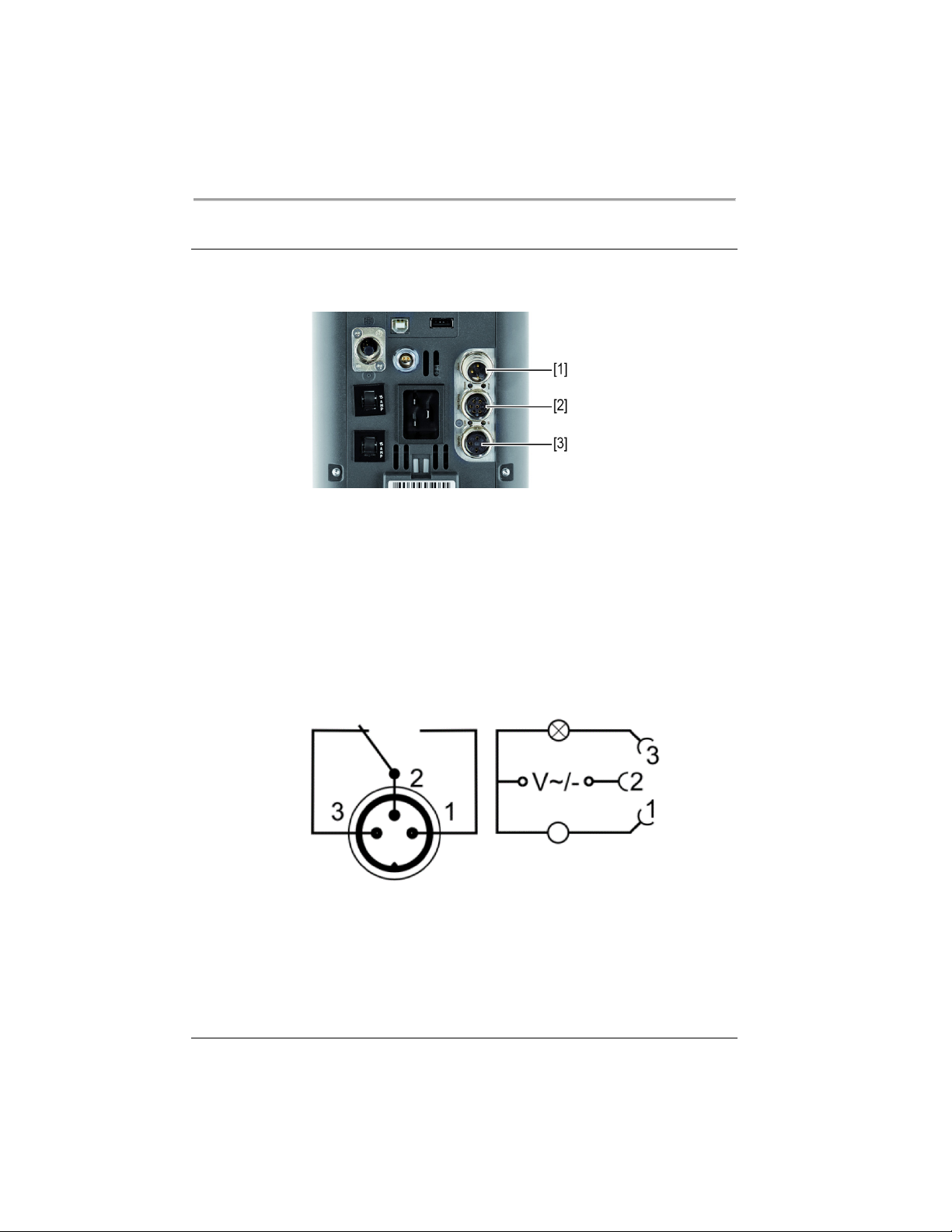
The analogue interfaces are optional and installed ex works.
Slide-in module with analogue connections
[1] Alarm output
[2] REG/EPROG plug
[3] Standby input
5.5.1 Alarm output
The alarm output is a potential-free changeover contact, through which an
externally connected circuit can be switched.
Alarm output diagram
20
Find Quality Products Online at: [email protected]
www.GlobalTestSupply.com
Page 21
Product description
Maximum switching current
1 A
In the <Analog module> menu, a defined state can be selected as the trigger
for the <Alarm output>.
When the respective state is reached, pins 2 and 3 are connected:
• Standby
• Alarm
• Alarm + Standby
When the respective state is reached, pins 1 and 2 are connected:
• Standby/Inverse
• Alarm/Inverse
• Alarm + Standby/Inverse
Alarm output technical data
Maximum switching capacity 30 W/25 VA
Maximum switching voltage 30 VDC/25 VAC
5.5.2 REG/EPROG socket
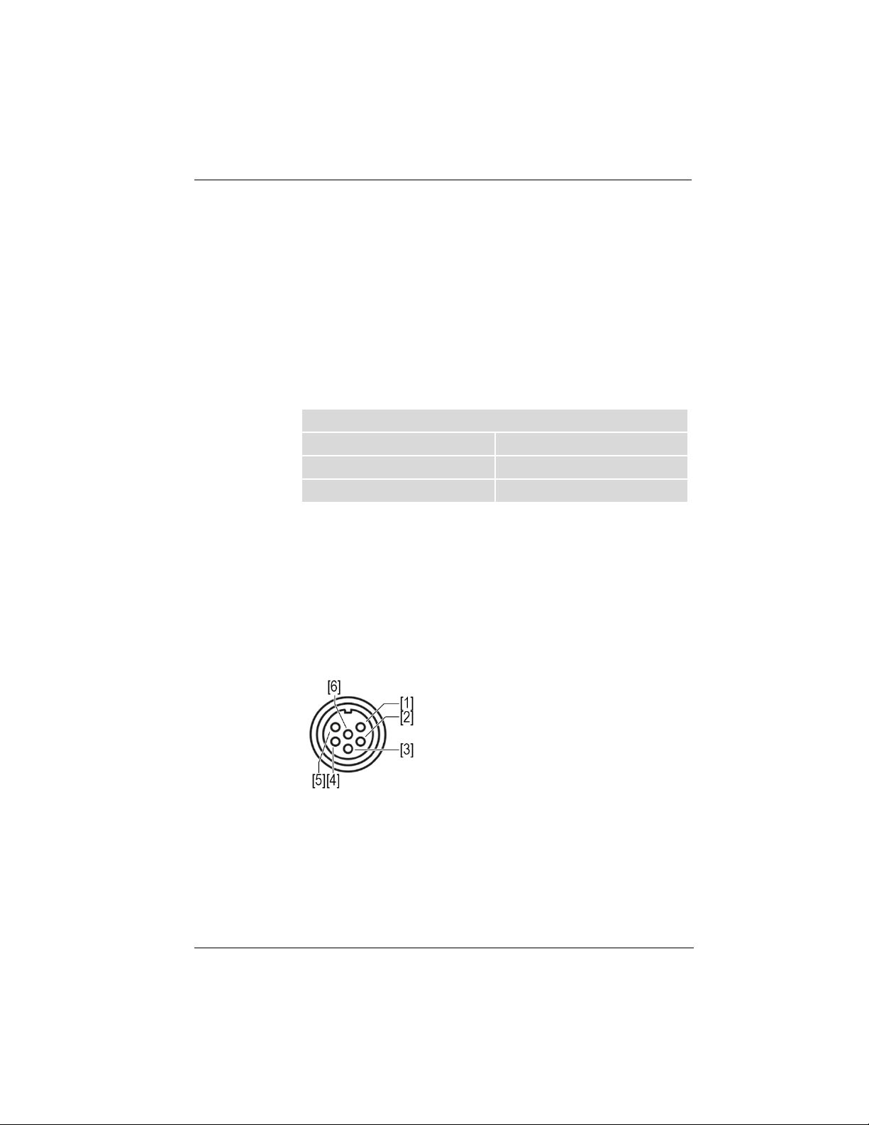
The REG/EPROG socket has three signal outputs and one signal input.
A signal transmitter connected to the programmer input can specify the setpoint
temperature or performance as a variable. The input signal can be a voltage
source or a current source.
The signal outputs can be used at the same time. Two of the three output
channels are designed as voltage outputs, the third as a current output.
REG/EPROG socket diagram
[1] Voltage output channel 1
(0-10 VDC, max. 10 mA)
[2] Voltage output channel 2
(0-10 VDC, max. 10 mA)
[3] Gnd for outputs (0 V)
[4] EPROG programmer
(0-10 VDC/0-20 mA, max. 24 VDC)
[5] Current output channel 3
(4-20 mA/0-20 mA, max. 24 VDC)
[6] Gnd for EPROG programmer (0 V)
21
Find Quality Products Online at: [email protected]
www.GlobalTestSupply.com
Page 22
Product description
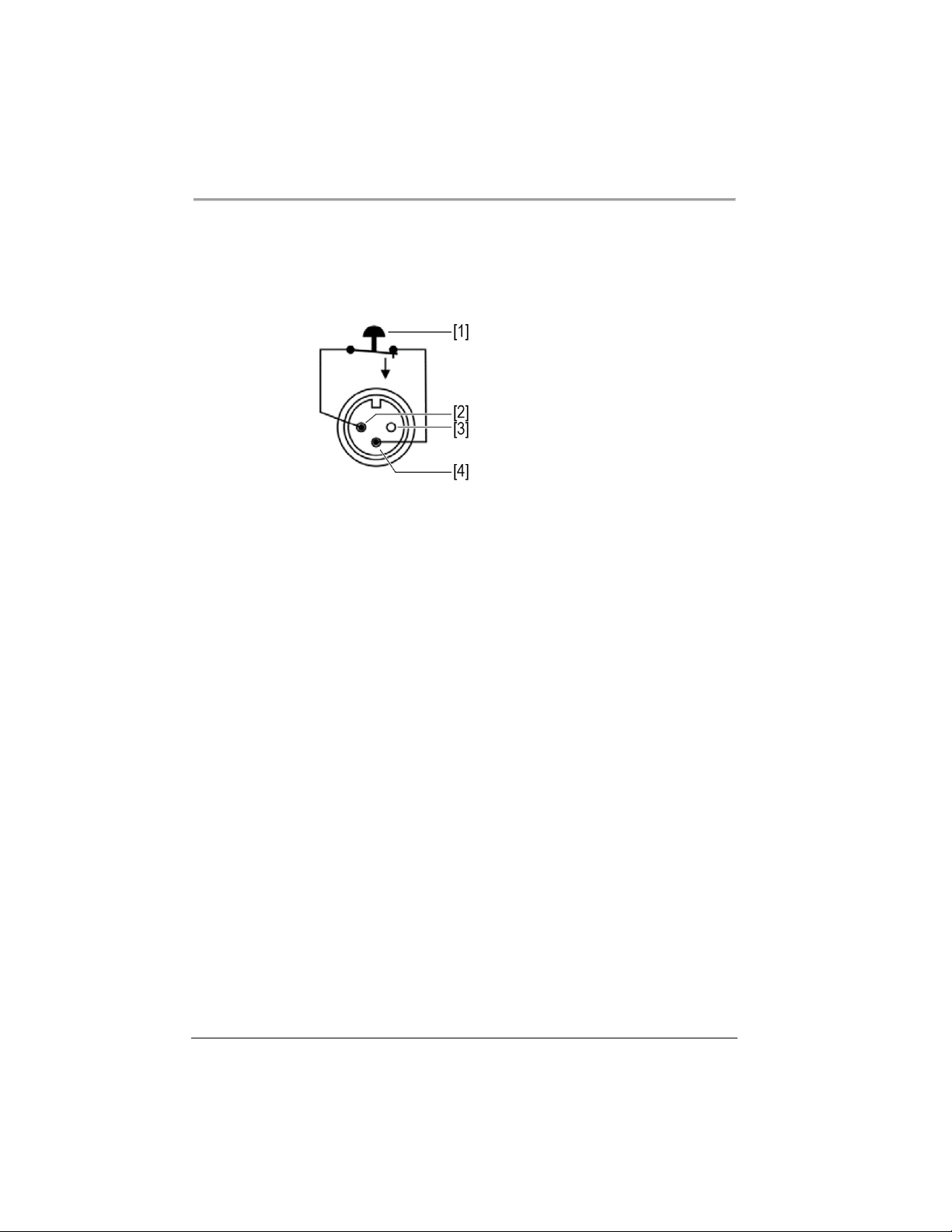
5.5.3 Standby input
With the standby socket the device can be put in standby mode using an
external signal transmitter.
Standby socket diagram
[1] External contact, e.g. switch
[2] Pin 3
[3] Pin 1
[4] Pin 2
22
Find Quality Products Online at: [email protected]
www.GlobalTestSupply.com
Page 23
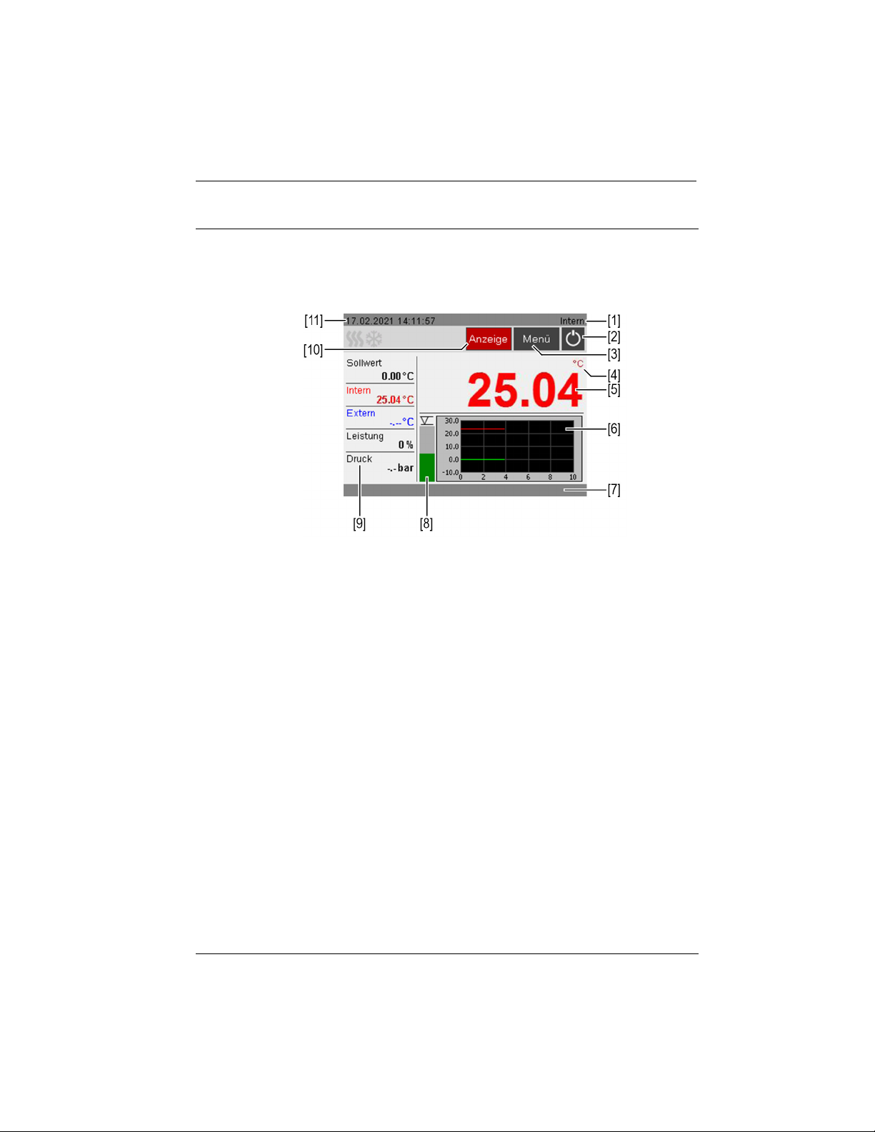
5.6 Operating interface
The device is operated using the central controller. When it is switched on, the
display shows the home screen. The [Display] softkey toggles between three
different views of the home screen.
Home screen
[1] Internal/external temperature control
[2] Start/Stop
[3] [Menu] softkey opens the <Main menu>
[4] Temperature unit: Celsius/Fahrenheit
[5] Display of current internal/external temperature, display off in standby
mode
[6] Temperature sequence setpoint temperature/current temperature internal
and external
[7] Status line for operator messages/alarms/warnings
[8] Fluid level display
[9] Display of current capacity parameters
[10] [Display] softkey swaps home screen views
[11] Date/time
Product description
23
Find Quality Products Online at: [email protected]
www.GlobalTestSupply.com
Page 24
Product description
5.6.1 Operation with the central controller
The central controller is used to control all menu functions and inputs on the
user interface. Selected menus, softkeys or input fields are highlighted in red.
Turning:
• navigates between menus, buttons and input fields
• sets values
Pressing:
• opens menus
• actuates softkeys and buttons
• activates input fields and selected functions
• confirms an entry
5.6.2 Softkeys and status icons
This section describes the softkeys and status icons found on the operating
interface.
Softkey Function
The [Start/Stop] softkey starts a temperature control
application or stops an ongoing temperature control
application
The [Home] softkey calls up the Home screen
Go back one menu level with the [Back] softkey
The [Help] softkey calls up the Help menu
The [Save] softkey saves entries
24
Find Quality Products Online at: [email protected]
www.GlobalTestSupply.com
Page 25
Product description
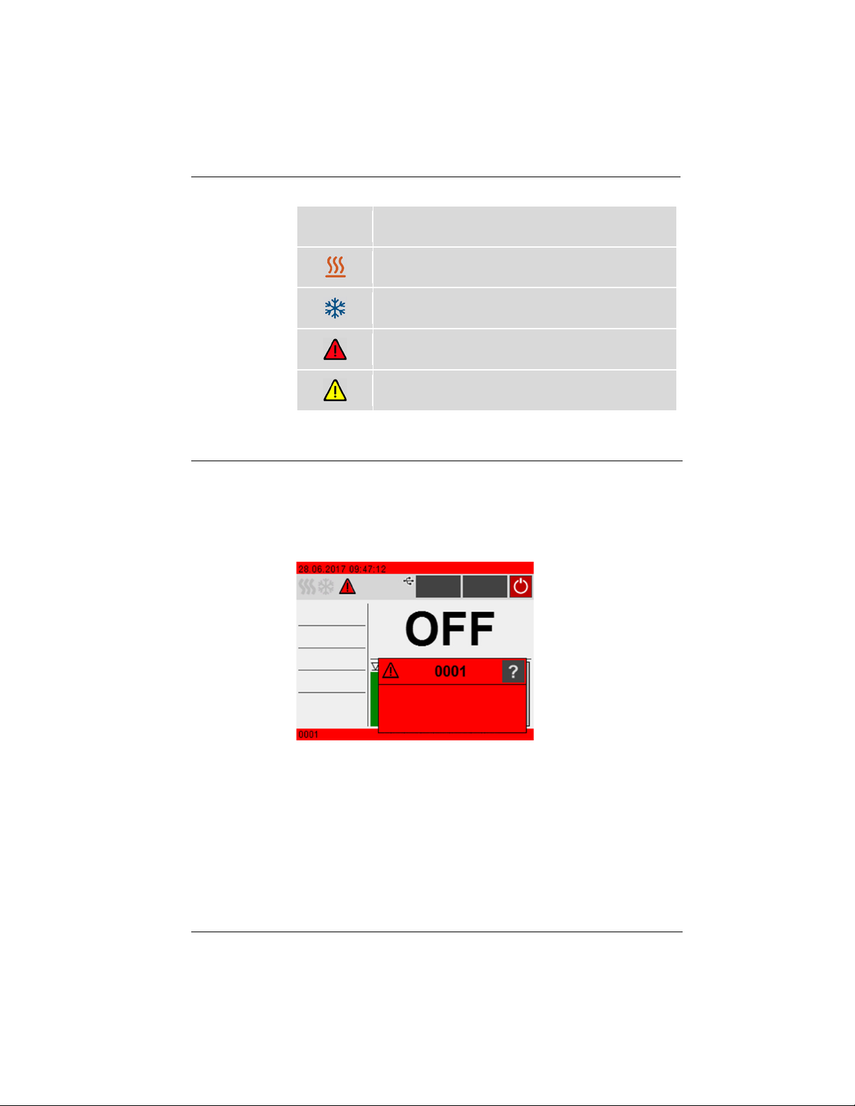
Symbol
5.7 Alarm messages
Errors or disturbances are indicated on the Home screen by alarm messages or
warnings. A help text is displayed by pressing the warning symbol with the
central controller. Important error code descriptions can be found in the
appendix. If you are unable to rectify a fault, contact Technical Service.
Description
Heating is active
Cooling is active
Alarm message
Warning message
Display of alarm message
Alarm:
In the event of an alarm, the tempering process is stopped. The actuators are
switched off. At the same time, a continuous acoustic signal sounds and an
alarm message with a red background is shown on the display. The acoustic
signal can be deactivated by pressing the central controller. The fault causing
the alarm must be remedied. A restart is required.
25
Find Quality Products Online at: [email protected]
www.GlobalTestSupply.com
Page 26
Product description
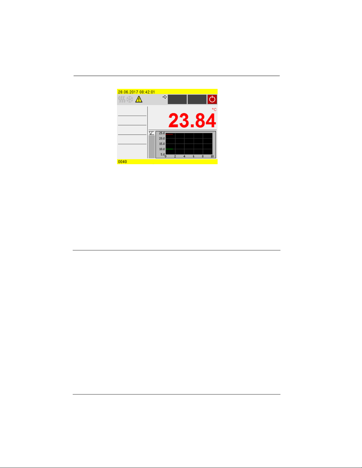
Display of warning message
Warning:
In the event of a warning, the tempering process is not interrupted. A warning
message with a yellow background is display. A signal tone is emitted at
intervals. The acoustic signal can be deactivated by pressing the central
controller. If the underlying cause of the warning is remedied, the signal tone
ceases. Depending on the cause, warnings may cease automatically after a
period of time, e.g. when the device cools down.
5.8 Operator Messages
Operator messages are informal messages that inform the operator about status
changes of the device.
Operator messages provide information about the operating states of individual
units on the status line of the home screen. Status messages from a connected
cooling machine are also displayed as operator messages.
26
Find Quality Products Online at: [email protected]
www.GlobalTestSupply.com
Page 27

5.9 Main menu
Bring up the Main menu using the [Menu] softkey on the home screen. The
Main menu is divided into menu options, which respectively contain more
submenus or in which settings can be specified. You can always get back to the
home screen using the [Home] softkey.
The <Main menu> is divided into the following menu options:
• Settings
• Record data
• Thermodynamics
• Adjust safety
• Programmer
• Connect unit
• Service
• Install unit
5.9.1 Settings menu
In the menu <Settings> the fundamental device settings are specified.
• Set language
• Set date and time
• Enable/disable autostart
• Set physical units
• Enable/disable key tones
Reading out the alarm memory
5.9.2 Record data menu
The device can record data on an external storage medium. The menu <Record
data> defines the conditions for this and starts recording. The recorded data
can be used for subsequent evaluation.
• Recording measurement data
• Reading out blackbox data
Product description
27
Find Quality Products Online at: [email protected]
www.GlobalTestSupply.com
Page 28

Product description
5.9.3 Thermodynamics menu
The control parameters for the temperature sequence are defined and the pump
capacity is set in the menu <Thermodynamics>.
Adjust controller:
• Setting for the control parameters for internal or external control
• Definition of the control behavior
• Specification of the limit values for heating capacity and cooling capacity
Adjust pump:
• Setting for pump mode
• Setting for pump capacity
5.9.4 Adjust safety menu
In the menu <Adjust safety> limit values are set to define a range for safe
process flow.
• Temperature limits: Setting for the upper and lower warning limits
• Setpoint limits: Setting for the upper and lower limits for temperature
setpoint
5.9.5 Programmer menu
The <Programmer> menu is used to program temperature sequences, which
can be called up according to definable rules.
• Timer: Setting for start time, duration and setpoint
• Profile timer: Timer function for individual profiles
• Profile series: Planning of individual profile series sequences
• Edit profile: Create, manage, import and export profiles
5.9.6 Menu Connect unit
The device can be connected with a PC and remote controlled using the USB
interface or the optional RS232 interface. In addition to this, external
programmers can also be connected via optional analog interfaces. In the menu
<Connect unit> parameters for remote control mode can be set.
• Remote control
• Digital interfaces
• External setpoint
• Analog interfaces
28
Find Quality Products Online at: [email protected]
www.GlobalTestSupply.com
Page 29

• Actuating variable
• Start up behavior
5.9.7 Service menu
The menu <Service> is reserved for JULABO service technicians and password
protected.
5.9.8 Install unit menu
In the menu <Install unit> several basic settings are specified. Depending on
the device configuration, not all menu functions may be available.
• Adjust external temperature sensor
• Import and export device settings
• Reset unit
• Set power supply
• Set chiller mode
Product description
29
Find Quality Products Online at: [email protected]
www.GlobalTestSupply.com
Page 30

Product description
5.10 Technical data
Performance specifications measured in accordance with DIN12876. Cooling
capacities up to 20°C measured with ethanol; over 20°C with thermal oil unless
specified otherwise. Performance specifications apply at an ambient
temperature of 20°C. Performance values may differ with other bath fluids.
Grouping of the device acc. to CISPR 11:
• The device is an ISM device of group 1, which uses high frequency for
internal purposes
• Class A: Use in an industrial electromagnetic environment
In accordance with IEC 61010-1, the device is designed for safe operation under
the following ambient conditions:
• Indoor use
• Altitude up to 2000 m above sea level
• Ambient temperature +5 … +40°C
• Maximum relative humidity 80% for temperatures up to 31°C, decreasing
linearly down to 50% relative humidity at 40°C
• Mains voltage fluctuations up to ±10% of the nominal voltage permissible
if not otherwise specified
• Pollution degree level 2
Protection class according to EN 60 529:
• Protection class IP21
30
Find Quality Products Online at: [email protected]
www.GlobalTestSupply.com
Page 31

Product description
DYNEO DD
Temperature control application
Working temperature range °C +20 … +200
Temperature stability °C ±0.01
Temperature resolution °C 0.01
Temperature control PID3
Temperature setting Digital
ATC sensor adjustment 3-point adjustment
Pump
Volume flow l/min 8 … 27
Supply pressure bar 0.1 … 0.7
Maximum viscosity cSt 50
Dimensions
Dimensions (W x D x H) cm 13.2 x 16.0 x 35.5
Immersion depth cm 16.0
Weight kg 2.5
Display
Display 3.5" TFT display
Performance data
Mains connection 100-115 V 50/60 Hz 200-230 V 50/60 Hz
100 V
50/60 Hz
115 V
50/60 Hz
200 V
50/60 Hz
230 V
50/60 Hz
Current consumption A 10 11 9 10
Heating capacity kW 0.8 1.0 1.5 2.0
Mains fuse, resettable A 15
31
Find Quality Products Online at: [email protected]
www.GlobalTestSupply.com
Page 32

Product description
5.10.1 Material of parts that come into contact with the medium
The table lists parts that could come into contact with the bath fluid as well as
the material that the parts are made of. This data can be used to check the
compatibility of the parts with the bath fluid used.
Parts that come into contact with the
Material
medium
Motor 1.4301
Motor shaft 1.4404
Pump PPS
Heating element 1.4404/316L
Inbuilt temperature sensor Pt100 1.4571
Connection of temperature sensor 1.4301
Float 1.4401
Float pipe 1.4571
Hose olive 1.4301
Single-ear clamp 1.4301
Hose FPM/FKM
32
Find Quality Products Online at: [email protected]
www.GlobalTestSupply.com
Page 33

Product description
Volumes min. … max.
l
3.0 … 4.0
5.10.2 Technical data for refrigerated circulators
This section lists the technical data of the refrigerated circulator.
Technical data DYNEO DD-200F
Working temperature range °C -20 … +200
Cooling capacity °C +20 +10 0 -10 -20
Refrigerant R134A
Dimensions
Dimensions (W x D x H) cm 23 x 39 x 65
Usable bath opening cm 13 x 15
Bath depth cm 15
Weight kg 25.7
Technical data DYNEO DD-201F
Working temperature range °C -20 … +200
Cooling capacity °C +20 +10 0 -10 -20
Refrigerant R134A
Dimensions
Dimensions (W x D x H) cm 44 x 41 x 44
Usable bath opening cm 13 x 15
Bath depth cm 15
Volumes min. … max. l 3.0 … 4.0
Weight kg 24.7
kW 0.20 0.17 0.15 0.10 0.02
kW 0.20 0.17 0.15 0.10 0.02
33
Find Quality Products Online at: [email protected]
www.GlobalTestSupply.com
Page 34

Product description
Technical data DYNEO DD-300F
Working temperature range °C -25 … +200
Cooling capacity °C +20 +10 0 -10 -20
kW 0.30 0.30 0.27 0.19 0.08
Refrigerant R134A
Dimensions
Dimensions (W x D x H) cm 24 x 42 x 66
Usable bath opening cm 13 x 15
Bath depth cm 15
Volumes min. … max. l 3.0 … 4.0
Weight kg 27.7
Technical data DYNEO DD-310F
Working temperature range °C -30… +200
Cooling capacity °C +20 0 -10 -20 -30
kW 0.30 0.27 0.21 0.12 0.02
Refrigerants R449A, R290
Dimensions
Dimensions (W x D x H) cm 23 x 40 x 65
Usable bath opening cm 13 x 15
Bath depth cm 15
Volumes min. … max. l 3.0 … 4.0
Weight kg 27.4
at 200-230 V / 50/60 Hz permissible voltage deviation is ±5 %
34
Find Quality Products Online at: [email protected]
www.GlobalTestSupply.com
Page 35

Product description
Technical data DYNEO DD-449F
Working temperature range °C -30 … +200
Cooling capacity °C +20 0 -10 -20 -30
kW 0.44 0.35 0.27 0.20 0.06
Refrigerants R290
Dimensions
Dimensions (W x D x H) cm 39 x 62 x 75
Usable bath opening cm 28 x 35
Bath depth cm 20
Volumes min. … max. l 21.0 … 30.0
Weight kg 39.5
45
Technical data DYNEO DD-450F
Working temperature range °C -30 … +200
Cooling capacity °C +20 0 -10 -20 -30
kW 0.44 0.37 0.27 0.16 0.06
Refrigerants R449A, R290
Dimensions
Dimensions (W x D x H) cm 23 x 40 x 65
Usable bath opening cm 13 x 15
Bath depth cm 15
Volumes min. … max. l 3.0 … 4.0
Weight kg 27.4
at 200-230 V / 50/60 Hz permissible voltage deviation is ±5 %
35
Find Quality Products Online at: [email protected]
www.GlobalTestSupply.com
Page 36

Product description
Refrigerant
R449A, R452A*
Dimensions (W x D x H)
cm
33 x 47 x 74
Technical data DYNEO DD-600F
Working temperature range °C -35 … +200
Cooling capacity °C +20 +10 0 -10 -20 -30
R452A* kW 0.60 0.54 0.50 0.33 0.19 0.07
R449A kW 0.60 0.54 0.44 0.27 0.16 0.04
Refrigerant R449A, R452A*
Dimensions
Dimensions (W x D x H) cm 33 x 47 x 69
Usable bath opening cm 22 x 15
Bath depth cm 15
Volumes min. … max. l 5.0 … 7.5
Weight kg 35.7
at 200-230 V 50/60 Hz permissible voltage deviation ±5 %,
* at 100 V 50/60 Hz
Technical data DYNEO DD-601F
Working temperature range °C -35 … +200
Cooling capacity °C +20 +10 0 -10 -20 -30
R452A kW 0.60 0.54 0.50 0.33 0.19 0.07
R449A kW 0.60 0.54 0.44 0.27 0.16 0.04
Dimensions
Usable bath opening cm 22 x 15
Bath depth cm 20
Volumes min. … max. l 8.0 … 10.0
Weight kg 38.2
at 200-230 V 50/60 Hz permissible voltage deviation ±5 %,
* at 100 V 50/60 Hz
36
Find Quality Products Online at: [email protected]
www.GlobalTestSupply.com
Page 37

Product description
Technical data DYNEO DD-900F
Working temperature range °C -38 … +200
Cooling capacity °C +20 +10 0 -10 -20 -30
kW 0.90 0.85 0.80 0.52 0.31 0.11
Refrigerant R449A
Dimensions
Dimensions (W x D x H) cm 39 x 62 x 75
Usable bath opening cm 26 x 35
Bath depth cm 20
Volumes min. … max. l 21.0 … 30.0
Weight kg 52.0
Technical data DYNEO DD-1000F
Working temperature range °C -50 … +200
Cooling capacity °C +20 0 -10 -20 -30 -40
kW 1.00 0.96 0.73 0.51 0.25 0.11
Refrigerant R449A
Dimensions
Dimensions (W x D x H) cm 42 x 49 x 70
Usable bath opening cm 18 x 13
Bath depth cm 15
Volumes min. … max. l 5.0 ... 7.5
Weight kg 51.2
at 200-230 V / 50/60 Hz permissible voltage deviation is ±5 %
37
Find Quality Products Online at: [email protected]
www.GlobalTestSupply.com
Page 38

Product description
Technical data DYNEO DD-1001F
Working temperature range °C -38 … +100
Cooling capacity °C +20 +10 0 -10 -20 -30
kW 1.00 0.95 0.85 0.60 0.32 0.12
Refrigerant R449A
Dimensions
Dimensions (W x D x H) cm 45 x 64 x 95
Usable bath opening cm 35 x 41
Bath depth cm 30
Volumes min. … max. l 42.0 … 56.0
Weight kg 73.7
Technical data DYNEO DD-1000FW
Working temperature range °C -50… +200
Cooling capacity °C +20 0 -10 -20 -30 -40
kW 1.00 0.96 0.73 0.51 0.25 0.11
Refrigerant R449A
Dimensions
Dimensions (W x D x H) cm 42 x 49 x 70
Usable bath opening cm 18 x 13
Bath depth cm 15
Volumes min. … max. l 5.0 … 7.5
Weight kg 51.2
at 200-230 V / 50/60 Hz permissible voltage deviation is ±5 %
38
Find Quality Products Online at: [email protected]
www.GlobalTestSupply.com
Page 39
5.10.3 Bath fluids
NOTE
NOTE
The most important criterion when selecting the bath fluid is the working
temperature range in which the application is operated.
• Selection of the bath fluid must ensure that the flash point is never
• Recommended bath fluids and further information can be found on our
No liability accepted for usage of bath fluids that are not
suitable!
Unsuitable bath fluids that are not approved by JULABO can damage the
water bath.
• Use bath fluids that are recommended by JULABO
• Before filling, check the parts that are in contact with the medium for
• Do not exceed the maximum permissible viscosity during operation
• Consult JULABO before using a bath fluid other than the recommended
Product description
exceeded when it comes into contact with the ambient air.
website
compatibility with the bath fluid
one
Material damage caused by freezing water!
Freezing water can damage the device and the sample.
• When using water as the tempering fluid, do not temper below 5°C
Water as bath fluid
• Water can be used for working temperatures from +5 °C to +90 °C
• Recommended: Use only ultrapure or distilled water.
• When using ultrapure or distilled water, add 0.1 g Na
per liter of water.
2CO3
39
Find Quality Products Online at: [email protected]
www.GlobalTestSupply.com
Page 40

Product description
5.10.4 Hoses
Hoses for connection of an external system must suit the working temperature
range and the respective temperature control application.
Hoses for every area of application can be found on our website.
Hoses must meet the following requirements:
• Temperature resistance
• Pressure resistance
• Suitable material properties for the bath fluid used
40
Find Quality Products Online at: [email protected]
www.GlobalTestSupply.com
Page 41
6 Transport and installation
CAUTION
• Wear personal protective equipment
CAUTION
• Wear protective gloves
This section describes how to transport the unit safely.
6.1 Transporting the device
A circulator can be transported with the cooling machine when mounted.
Risk of crushing by falling device!
A device that is not secured appropriately can fall down during improper
transport and cause crushing injuries.
• Secure the device against tipping and falling during transport
• Secure loose parts against falling during transport
• Transport the device upright and with a suitable means of transport
Transport and installation
Burn hazard on the heating element!
The heating element may still be hot even after the device has been switched
off, and may cause burns if touched.
• Allow the device to cool down to room temperature after switching off
The device is switched off and emptied.
A suitable transport trolley is available.
1. Unplug the power plug from the device.
2. If necessary, disassemble the temperature control hoses of the external
system.
3. Use the recessed grips on the cooling machine to lift the device onto the
center of the transport trolley, if necessary in a pair.
See the technical data for weight information.
4. Use straps to secure the device against tipping in the center of the transport
trolley.
5. Place loose parts for the device, such as cables, on the transport trolley.
The device is then ready for transport and can be safely transported to its
installation location.
41
Find Quality Products Online at: [email protected]
www.GlobalTestSupply.com
Page 42

Transport and installation
6.2 Install the device at the operating location
This section describes how the device is set up at the installation location.
The device has been transported to the operation location.
The size and infrastructure of the operation location are suitable for device
operation.
1. If possible, position the device under an extraction system.
Depending on the bath fluid, gases may be created at high temperatures.
Recommended minimum distance of 1 m to other devices, to prevent
electromagnetic interference.
2. Place the device on a level, smooth, non-flammable surface.
3. Ensure that the device is securely positioned.
4. For refrigerated circulators: Ensure an open space in front of and behind the
device of at least 20 cm.
The device is set up at the operation location.
42
Find Quality Products Online at: [email protected]
www.GlobalTestSupply.com
Page 43
7 Initial operation
7.1 Mounting the circulator
7.1.1 Mount heating or refrigerated circulator
In the case of a heating circulator or a refrigerated circulator, the circulator is
mounted on the closed bath or on cooling machine.
If the circulator is disassembled, e.g. due to a change of device or for service
purposes, it can then be easily reassembled with the connecting box.
Allen key, size 3 mm
The circulator is ready to be mounted on a closed bath or cooling machine.
The bath is empty.
Initial operation
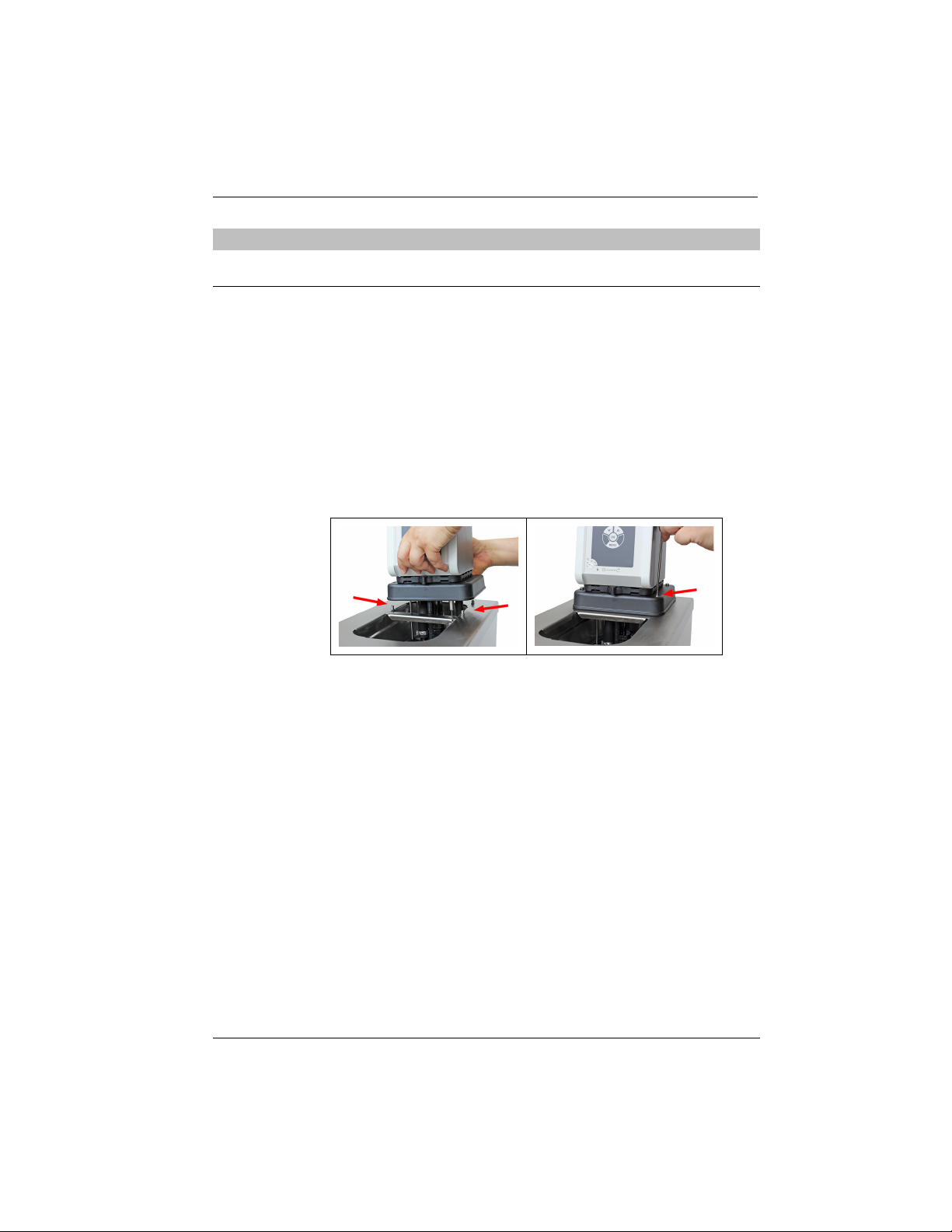
1. Carefully insert the circulator into the bath.
Align the bath's four threaded sleeves with the four holes on the connection
box.
2. Place the four mounting screws into the holes on the connection box.
3. Tighten the mounting screws [right image].
4. Check that the circulator is seated correctly, and that the connection box
gasket is seated on the unit surface without any gaps.
The heating circulator or refrigerated circulator is mounted.
43
Find Quality Products Online at: [email protected]
www.GlobalTestSupply.com
Page 44
Initial operation
7.2 Connect the device to the power supply
7.2.1 Connect bridge mounted or heating circulator
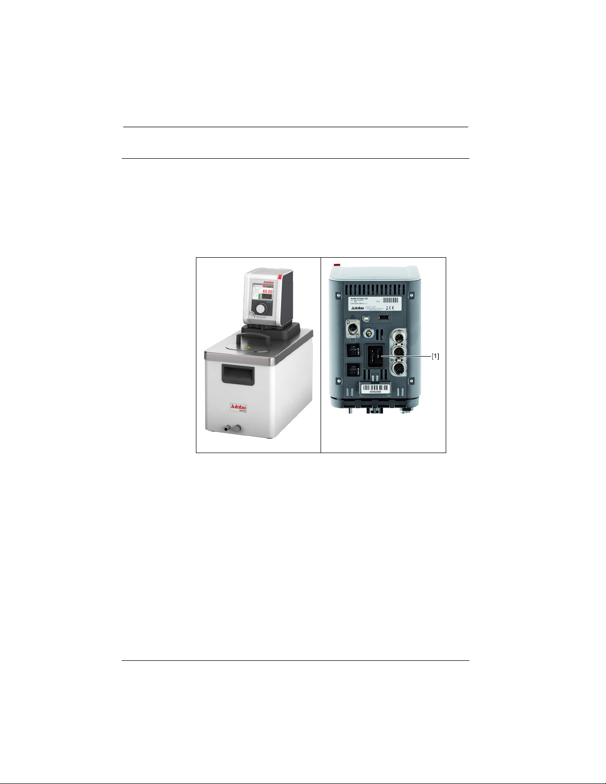
This section describes how the circulator is connected as a bridge mounted
circulator or heating circulator.
The circulator is mounted as a bridge mounted or heating circulator.
The power cable is ready for use.
1. Insert the power cable on the back of the circulator into the mains
connection [1].
2. Connect the circulator to the power supply using the power cable.
The circulator is connected.
44
Find Quality Products Online at: [email protected]
www.GlobalTestSupply.com
Page 45
7.2.2 Connect refrigerated circulator
This section describes how the circulator is connected as a refrigerated
circulator.
The circulator is mounted on a refrigeration unit.
The connection cable, mains cable and CAN bus cable are ready for use.
Initial operation
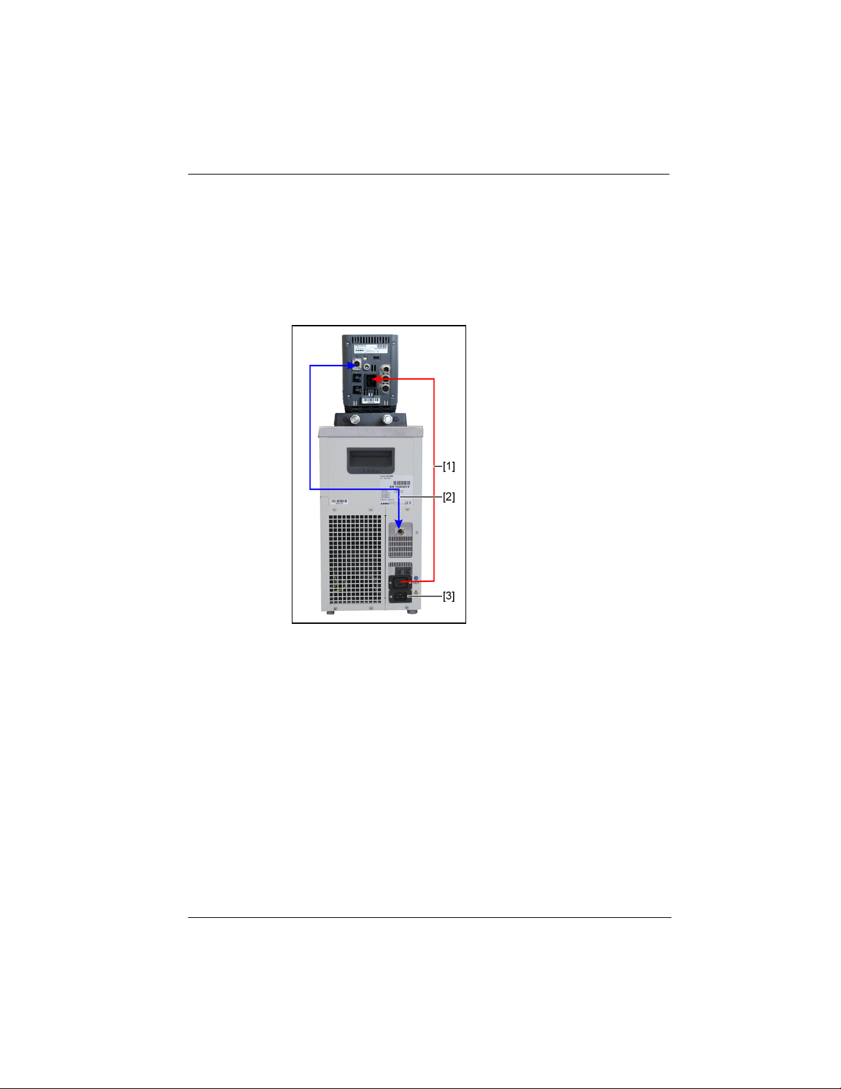
1. Connect the connection cable [1] of the circulator with the refrigeration
unit.
2. Connect the CAN plugs of both units with the CAN bus cable [2].
3. Connect the refrigeration unit to mains power [3] using the power cable.
The refrigerated circulator is connected. Alternatively, the units can be
connected to separate circuits. If necessary, the power supply must be set
up in the unit setting.
45
Find Quality Products Online at: [email protected]
www.GlobalTestSupply.com
Page 46
Initial operation
CAUTION
NOTE
NOTE
7.3 Connecting an external system
The device is designed for tempering external, closed loop systems. An external
system is connected to the unit’s pump connections.
Risk of burns due to damaged temperature control hoses!
Hot bath fluid can escape from damaged temperature control hoses and
cause serious burns when it comes into contact with skin.
• Check the temperature control hoses regularly for integrity
• Immediately replace damaged temperature control hoses
• Do not kink temperature control hoses
• Regularly exchange temperature control hoses
• Check the pump connections for leak tightness
Material damage due to incompatible externally connected
system!
If the temperature range and/or pressure parameters of an externally
connected system do not match those of the device this can result in damage
to individual components or even failure of the entire system.
• Before connection check the external system for compatibility with the
device combination
• If an external system is connected that is not set up for the maximum
pressure of the device, the pump's flow rate must be limited in the
settings
• If an external system is connected, the safety of the entire system is the
responsibility of the operator
Hot pump connections!
The pump connections can become very hot during operation. Heat-sensitive
parts or cables can be damaged if they have contact.
• Pump connections must be uncovered during operation
• No loose parts or cables should come into contact with pump connections
during operation
46
Find Quality Products Online at: [email protected]
www.GlobalTestSupply.com
Page 47
NOTE
Overflowing bath fluid due to externally connected systems!
NOTE
If the externally connected system is higher than the temperature control
system, bath fluid can flow back and overflow when switched off.
• Position the connected external system on the same level or lower than
the temperature control system
• Position a shut-off valve or Solenoid valve between the external system
and the temperature control system as backflow protection.
Initial operation
Damaged hoses due to kinking!
Hoses are damaged by kinking and can may leak.
• Lay hoses with large radii
• Avoid kinking of the hoses
7.3.1 Connect an external system with screw connections
This section describes how to connect an external, closed system to the device
using screw connectors.
Open-end wrench, 17 mm
Open-end wrench, 19 mm
Torque wrench
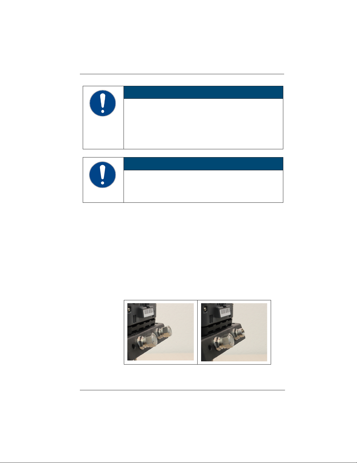
The circulator is equipped with the optional assembly frame or pump set.
The temperature control hoses of the external system are equipped with
M16x1 female and barrel gaskets.
1. Remove the union nuts on the pump connections.
47
Find Quality Products Online at: [email protected]
www.GlobalTestSupply.com
Page 48
Initial operation
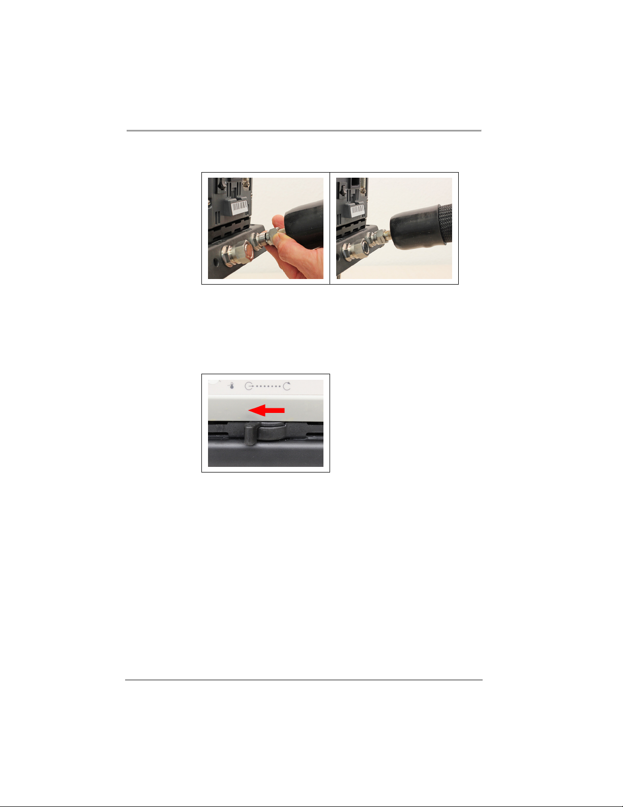
2. Remove the sealing plugs.
3. Screw the hoses onto the pump connections by hand.
Pay attention to the supply and runback position.
4. Carefully tighten the pump connections with a maximum torque of 3 Nm.
Brace the nut (width across flats: 17 mm) using an open-end wrench.
Warning! Over-tightening the pump connections may cause the assembly
frame to break.
5. Set the flow direction lever to external circulation.
The external system is connected.
If the external system is disassembled, the pump connections must be
resealed with the sealing plugs so that no bath fluid can splash out during
operation.
48
Find Quality Products Online at: [email protected]
www.GlobalTestSupply.com
Page 49
7.3.2 Connect an external system with barbed fittings
This section describes how to connect an external, closed system to the device
using barbed fittings.
Open-end wrench, 17 mm
Open-end wrench, 19 mm
Torque wrench
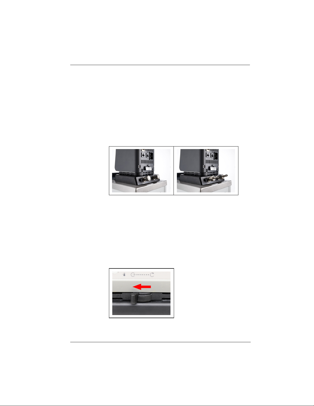
The circulator is equipped with the optional assembly frame or pump set.
Barbed fittings are provided to install the external system.
1. Remove the union nuts on the pump connections.
2. Remove the sealing plugs.
3. Push one barbed fitting through each of the union nuts.
4. Mount the barbed fittings with the union nuts on the pump connections.
5. Carefully tighten the union nut with a maximum torque of 3 Nm. Brace the
nut (width across flats: 17 mm) using an open-end wrench.
Warning! Over-tightening the pump connections may cause the assembly
frame to break.
6. Attach the external system's hoses to the barbed fittings.
Pay attention to the supply and runback position.
7. Using tube clamps, secure the hose to prevent it from slipping.
Initial operation
8. Set the flow direction lever to external circulation.
49
Find Quality Products Online at: [email protected]
www.GlobalTestSupply.com
Page 50

Initial operation
The external system is connected.
If the external system is disassembled, the pump connections must be
resealed with the sealing plugs so that no bath fluid can splash out during
operation.
7.4 Switch on the device and set the language
The language must be set first, to prepare for important basic settings. When
switching on for the first time, alarm messages may be shown on the display.
The device is connected and ready for operation.
1. Switch the device on at the mains switch.
The software boots and starts the device. The display shows the device
name, voltage version and software version.
Since no temperature liquid has been filled yet, the low level alarm is
displayed.
Depending on the default setting, the high temperature cut-off alarm is
displayed.
2. Call up the <Main menu>.
3. Call up the submenu <Settings> then menu option <Language>.
The submenu <Language> lists all the languages installed on the device.
4. Select the desired language.
5. Turn the device off so that the alarm message is reset.
The language is set.
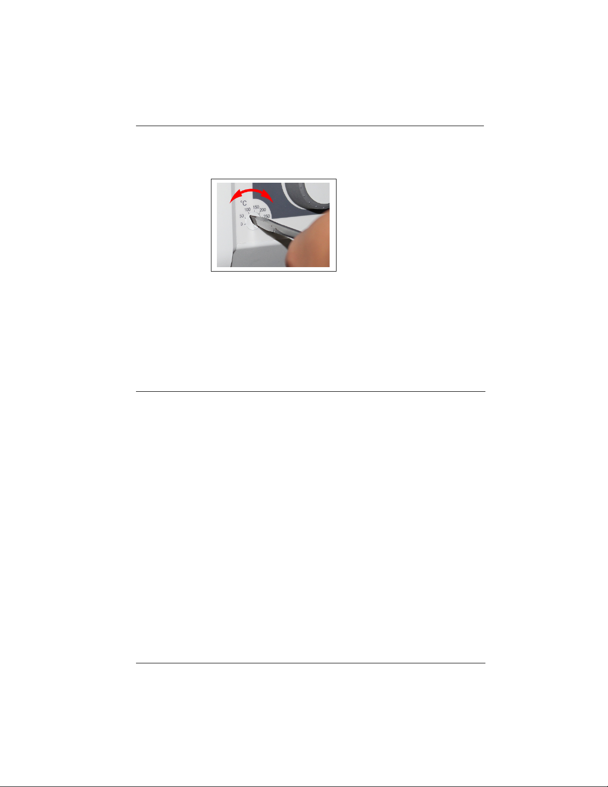
7.5 Set high temperature safety function
Before each new temperature application, the temperature must be set for the
tank and internal reservoir high temperature cut-off. Set a value that is at least
25 K below the flash point of the bath fluid being used. The surface temperature
of the bath fluid must not exceed the flash point at any time. An alarm is
triggered when the set value is exceeded.
Slotted screwdriver, size 3
The device is connected.
The language is set.
1. Switch the device on.
If no temperature liquid has been filled yet, the low liquid level alarm is
displayed.
Depending on the default setting, the high temperature cut-off alarm is
displayed.
50
Find Quality Products Online at: [email protected]
www.GlobalTestSupply.com
Page 51
7.6 Fill device
Initial operation
2. Press the [Display] softkey to select the home screen that displays the high
temperature cut-off value.
3. Use the screwdriver to set the overtemperature protection device.
The display shows the set value.
4. Set a value that is at least 25 K under the flash point of the bath fluid being
used.
The set value is immediately active.
5. Turn the device off so that the alarm message is reset.
The high temperature cut-off is set.
This section describes how the device should be filled with bath fluid during
initial operation.
Specifications for filling volume can be found in the technical data.
The drain valve is closed.
The unit is switched off.
1. Remove the bath lid.
2. Half fill the bath with bath fluid.
The bath fluid expands with increasing temperature and can overflow.
With decreasing temperature, the low liquid level protection can be
triggered and interrupt the temperature control process.
3. Switch the unit on and start the temperature control application.
If an external system is connected, the pump supply must be set to
“external” so that it fills the external system.
4. Watch the level indicator and, if necessary, adjust the level by refilling or
draining.
Once the working temperature has been reached and the sample inserted,
the level of bath fluid in the bath tank should cover the heating coil of the
heating circulator or the cooling coil of the cooling machine.
5. Close the bath opening with the bath lid.
The unit is filled with bath fluid.
51
Find Quality Products Online at: [email protected]
www.GlobalTestSupply.com
Page 52
Initial operation
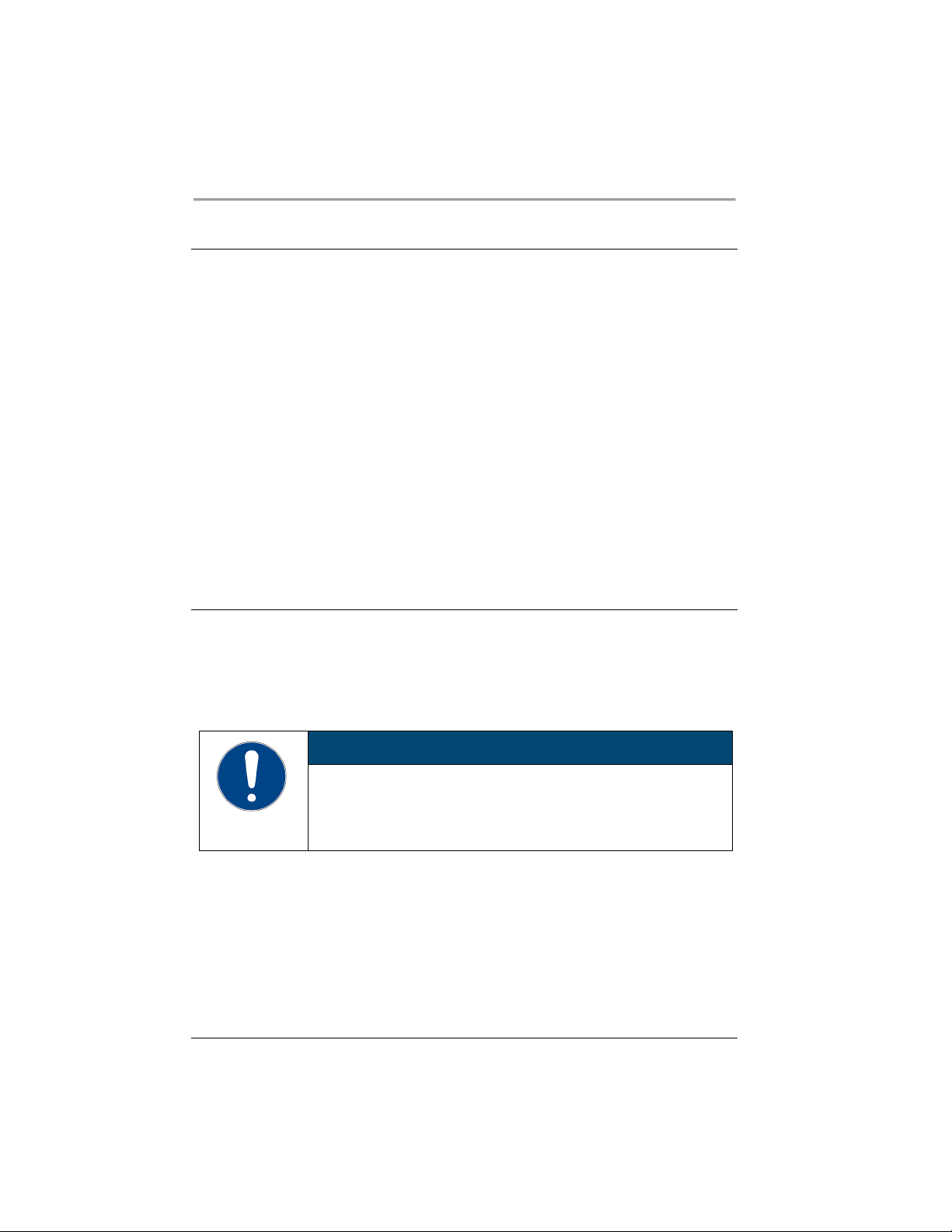
NOTE
7.7 Set up power supply for the refrigerated circulator
For a refrigerated circulator, the power supply is configured at the factory. The
circulator is supplied with power from the refrigeration unit. Alternatively, both
units can be connected to separate circuits with one power cable each. The type
of power supply is set in the operating menu.
The cooling machine is connected.
1. Switch the device on at the mains switch.
2. Call up the <Main menu>.
3.Call up the submenu <Install unit> then the menu option <Power supply>.3
4. Select the type of power supply: [Supply via chiller] for connection to the
same power grid or [Separate supply] for connection to a different power
grid.
[Supply via chiller] activates the heating capacity limit of the circulator.
It prevents the device combination from exceeding a defined maximum
current consumption and thus from overloading the power grid.
The power supply for the refrigerated circulator is set up.
7.8 Adjusting the flow of the bath fluid
The flow direction of the bath fluid is set using the lever on the front control:
• Lever position left (external): The bath fluid is mainly fed into the external
application.
• Lever position right (internal): The bath fluid is mainly circulated in the
internal bath.
Bath fluid squirts out!
If the pump connections are not sealed, bath fluid can squirt out even with
the flow direction set to internal.
• For internal temperature control, close the external pump connections
52
Find Quality Products Online at: [email protected]
www.GlobalTestSupply.com
Page 53
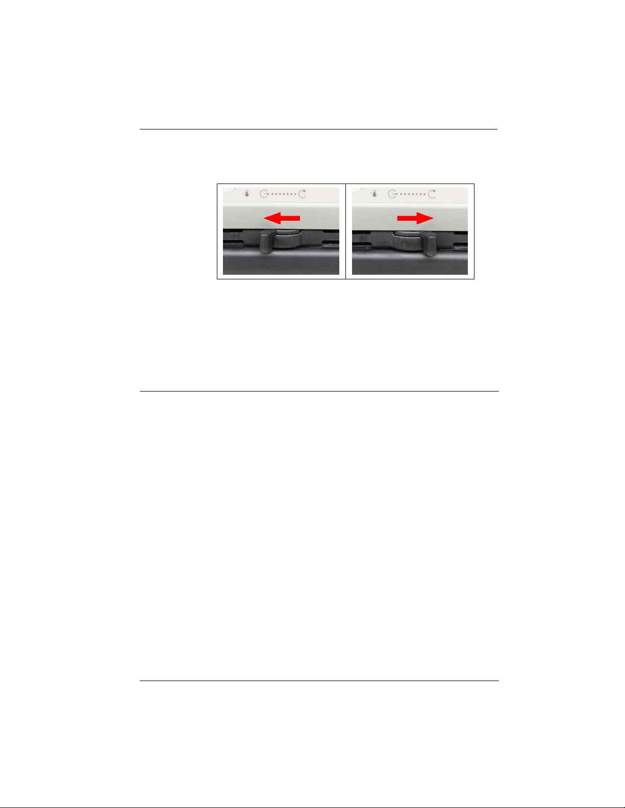
The device is switched off.
Bath fluid is filled.
1. Set the lever to a low level for internal circulation (e.g. position 2 from the
right stop).
2. Switch on the device and check whether the flow of the bath fluid suits your
application.
3. If necessary, adjust the flow until it suits your application.
The flow of the bath fluid is set.
7.9 Set chiller mode
For a refrigerated circulator, the chiller mode is preset ex works to automatic
operation. Three different chiller modes can be selected in the operating menu:
• Automatic mode: The controller calculates the duration of the heating
process in the event of a setpoint change of more than +5°K. Based on the
calculated heating duration, the control decides whether the refrigeration
unit is to be switched off or not, depending on demand.
• Always on: The refrigeration unit is permanently switched on during
operation.
• Always off: The refrigeration unit remains switched off during operation.
The device is switched on.
The cooling machine is connected.
1. Call up the <Main menu>.
2. Call up the submenu <Install unit> then the menu option
<Chiller mode>.
The menu option can only be called up if the thermostat detects a
connected refrigeration unit.
3. Select the desired chiller mode.
The chiller mode is set.
Initial operation
53
Find Quality Products Online at: [email protected]
www.GlobalTestSupply.com
Page 54

Initial operation
7.10 Set limit values
7.10.1 Set temperature warning limits
The low temperature and high temperature are adjustable temperature limits
that serve as warning limits for the device. If one of the warning limits is
exceeded during the course of a tempering process, then the device warns with
a signal tone and displays a warning message.
The device is switched on.
1. Bring up the <Main menu>.
2. From the <Adjust safety> submenu, select the menu option
<Temperature limits>.
A window opens with input fields for the temperature warning limits.
3. Enter a value for low temperature and high temperature then confirm your
entry.
Only values that are within the performance values of the device can be
entered.
The temperature warning limits are set.
7.10.2 Adjusting setpoint limits
The setpoint limits Setpoint max. and Setpoint min. define the upper and lower
limit of the adjustable setpoint temperature range.
The setpoint limit for the pump defines the upper limit value for pump speed,
adjustable in the menu <Thermodynamics>. The lower limit is set to 30% ex
works.
The maximum pressure setpoint defines the upper limit value for the pump
pressure that can be set in the menu<Thermodynamics>.
The device is switched on.
1. Bring up the <Main menu>.
2. From the <Adjust safety> submenu, select the menu option <Setpoint
limits>.
The dialog window for adjusting the setpoint limits appears on the display.
3. Set the setpoints and confirm your entry.
Only values that are within the performance values of the device can be
entered.
The setpoint limits are set.
54
Find Quality Products Online at: [email protected]
www.GlobalTestSupply.com
Page 55
7.10.3 Adjusting actual value limits
The actual value limits “internal minimum” and “internal maximum” are
effective in the external control operating mode. They define limits for the
expected temperature in the internal bath. The temperature controller cannot
exceed these limit values. Under certain circumstances, the external setpoint will
not be reached.
The device is switched on.
1. Bring up the <Main menu>.
2. From the <Thermodynamics> submenu, select the menu option
<Adjust controller>.
The dialog box for setting the controller appears on the display.
3. Switch to the submenu <Limits>.
4. Set the values for internal minimum and internal maximum in the dialog
window displayed.
The actual value limits are set and immediately active.
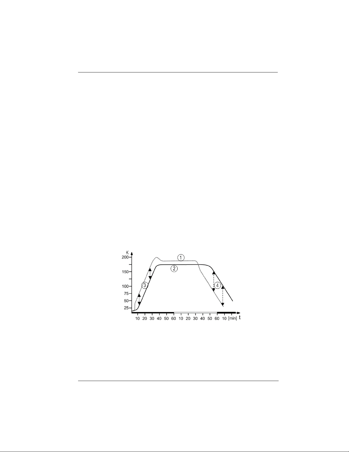
7.10.4 Band limit for external control
If an external system is being controlled then there is a temperature difference
both during the heating phase and the cooling phase due to inertia. The curve
illustrates the connection between the internal and external temperature
sequence.
Initial operation
Schematic temperature sequence internal/external
[1] Temperature sequence internal
[2] Temperature sequence external system
[3] Band limit upper
[4] Band limit lower
55
Find Quality Products Online at: [email protected]
www.GlobalTestSupply.com
Page 56

Initial operation
In order to gently control the temperature of a sample in an external system, or
to protect a glass reactor from thermal stress, for example, maximum
permissible temperature differences can be specified for the heating phase and
the cooling phase.
7.10.5 Setting band limit
The upper and lower band limit is defined in °K. In the heating phase the set
value will be added to the external actual value. In the cooling phase the set
value will be subtracted from the external actual value. The setting range is
between 1 and 200 °K.
The device is switched on.
1. Bring up the <Main menu>.
2. From the <Thermodynamics> submenu, select the menu option
<Adjust controller>.
The dialog box for setting the controller appears on the display.
3. Switch to the submenu <Limits>.
4. In the dialog box that appears, set the lower and upper band limits and
confirm your entry.
The band limits are set and immediately active.
7.11 Connect external temperature sensor
A Pt100 temperature sensor can be attached to the rear of the device.
B
The device is switched off.
A Pt100 temperature sensor with suitable connection is available.
1. Connect the Pt100 to the ext.Pt100 socket on the back of the device.
2. Switch the device on.
3. From the <Thermodynamics> submenu, select the menu option
<Adjust controller>.
4. Enable the menu option [External] for external control.
5. Bring up the menu option <Control behavior>.
6. Set the control parameter for external control.
The external temperature sensor is connected and ready for operation.
56
Find Quality Products Online at: [email protected]
www.GlobalTestSupply.com
Page 57

8 Operation
8.1 Switch on the unit
This section describes how to switch on the device.
The unit is connected and ready for operation.
1. Switch the unit on at the mains switch.
The software boots and starts the unit. The display shows the unit name,
voltage version and software version.
The unit is switched on. It switches to the most recently activated operating
mode, manual mode of operation or remote control mode. If the auto start
function is activated, then the unit starts directly into the last setting.
If remote control mode is enabled, operation at the device is not possible.
First, deactivate the remote control mode.
8.2 Switch off the unit
This section describes how to switch off the device.
The device is switched on.
1. Stop a running temperature control application.
If a cooling machine is connected, the cooling symbol flashes and the
cooling machine is shut down.
Do not switch off the device until the cooling symbol stops flashing and the
device is in standby mode.
2. Switch the device off at the mains switch.
The device is switched off.
8.3 Start temperature control application
A temperature application can be started directly on the unit. Other options
include timer-controlled temperature control application with the integrated
programmer and remote control via a connected PC.
The unit is switched on.
1. Activate the <Setpoint> field on the Home screen with the central
controller.
2. Enter the desired setpoint and confirm your input.
Operation
57
Find Quality Products Online at: [email protected]
www.GlobalTestSupply.com
Page 58

Operation
3. Press the [Start/Stop] softkey.
The unit starts the temperature control application at once. The temperature
control application can be stopped with the [Start/Stop] softkey. The
entered setpoint is saved.
Observe the following for heating circulators:
For temperature control applications near or below the ambient
temperature: Use a cooling coil or JULABO immersion cooler.
8.4 Basic settings
8.4.1 Set language
The language of the operating interface can be switched to one of the available
languages.
The device is switched on.
1. Call up the <Main menu>.
2. Call up the submenu <Settings> then menu option <Language>.
The submenu <Language> lists all the languages installed on the device.
3. Select the desired language.
The selected language is immediately activated.
8.4.2 Set date and time
The date and time is preset ex works. This section describes how you can set the
date and time yourself.
The device is switched on.
1. Call up the <Main menu>.
2. Call up the submenu <Settings> then menu option <Date/time>.
The submenu shows the currently set date and time as well as selectable
display formats.
3. Set the date and time and then confirm your settings.
4. Save the settings with the [Save + Esc] softkey.
5. Select one of the check boxes to display the date and time in a different
format.
The date and time are set.
58
Find Quality Products Online at: [email protected]
www.GlobalTestSupply.com
Page 59

8.4.3 Activate autostart function
The autostart function makes it possible to start a temperature control
application directly using the mains switch or via an intermediate timer.
The device is configured ex works in such a ways that it switches to a safe
operating status in the event of power failure. The autostart function is
deactivated. The display shows “OFF.” The refrigeration aggregate, heater, and
pump motor are disconnected from the mains voltage.
The device is switched on.
1. Bring up the <Main menu>.
2. From the <Settings> submenu, select the menu option <Autostart>.
3. Check the <On> box and confirm your setting.
The autostart function is activated. The next time the device is switched on,
the temperature control application will immediately start with the preset
values. You can also connect and program a timer. In this case the mains
switch must remain on.
8.4.4 Set physical units
The physical units for temperature, pressure and flow can be set in the menu.
The device is switched on.
1. Bring up the <Main menu>.
2. From the <Settings> submenu, select the menu option <Units>.
3. Select the check boxes to display the desired units for temperature, pressure
and flow.
The physical units are set.
8.4.5 Set key tones
The device key tones can be enabled and disabled in the menu.
The device is switched on.
1. Bring up the <Main menu>.
2. From the <Settings> submenu, select the menu option <Key tones>.
3. Enable or disable the key tones.
The key tones are set. The setting is applied directly.
Operation
59
Find Quality Products Online at: [email protected]
www.GlobalTestSupply.com
Page 60

Operation
8.5 Record data
8.5.1 Record measurement data
Measurement data for an ongoing temperature control application can also be
recorded onto a USB stick at the same time. The record documents the date,
time, setpoint temperature, intern actual value, external actual value and the
percentage power. The data is saved as a .txt file and can be subsequently
analyzed.
The device is switched on.
A USB stick is available.
1. Bring up the <Main menu>.
2. Bring up the <Record data> submenu.
The warning appears: “Please insert a USB stick!”.
3. Insert the USB stick into the USB socket on the back of the device.
4. Bring up the <Start measurement data recording on USB stick>
submenu.
5. Set the sampling interval from 1 to 60 seconds and confirm your setting.
6. Press the [Start] softkey.
7. If necessary, change the file name.
8. Confirm with the [OK] softkey.
The measurement data recording is started. The data is recorded at the
specified interval until you press the [Stop recording] softkey.
8.5.2 Reading out blackbox data
The blackbox stores all relevant data from the last 30 minutes. In addition, the
black box logs alarms and warnings.
The blackbox can be read out and the data sent to technical service for analysis.
The device is switched on.
A USB stick is available.
1. Bring up the <Main menu>.
2. Bring up the <Record data> submenu.
The warning appears: “Please insert a USB stick!”.
3. Insert the USB stick into the USB socket on the back of the device.
4. Bring up the <Save blackbox on USB stick> submenu.
5. If necessary, change the displayed file name.
6. Confirm with the [OK] softkey.
The blackbox data is saved onto the USB stick as a .txt file.
60
Find Quality Products Online at: [email protected]
www.GlobalTestSupply.com
Page 61

8.5.3 Displaying alarm memory
Alarm messages are stored with date, time, alarm code and unit identifier. The
data can be read out via the menu.
The device is switched on.
1. Bring up the <Main menu>.
2. From the <Settings> submenu, select the menu option <Alarm
memory>.
The device lists the stored alarm messages.
3. Press the [Clear] softkey to delete all entries.
The alarm memory is displayed and cleared.
Operation
61
Find Quality Products Online at: [email protected]
www.GlobalTestSupply.com
Page 62

Operation
8.6 Thermodynamics
8.6.1 Control parameter
The device works with a PID control. Experience has shown that the control
parameters set ex works achieve an optimal temperature sequence in the
sample.
The internal and external control parameters can be adjusted in the submenu
<Control performance>.
For internal control, the control dynamic can be set to either Standard or
Aperiodic:
• With Aperiodic the temperature increase is temporally offset, so that the
actual temperature doesn’t overshoot
• With Standard the temperature increase is faster, but the actual
temperature can overshoot by up to 5%
Proportional range Xp
The proportional range Xp is the temperature range between the setpoint value
and the actual value, in which the heating capacity can be adjusted from 100%
to 0%. The value for Xp can be selected between 0 K and 10 K.
Integral controller Tn
The integral controller Tn is indicated in seconds. It reduces the difference
between the setpoint value and the actual value caused by the Xp component,
and keeps to the setpoint value.
Differential controller Tv
The differential controller Tv is specified in seconds. It shortens the regulation
time.
CoSpeed factor
The CoSpeed factor affects the temperature sequence when used with external
control. It directly affects Xpu and causes more aggressive temperature control.
Proportional range Xpu
The proportional range Xpu plays a role in external control. It corresponds with
the proportional range Xp for internal control.
62
Find Quality Products Online at: [email protected]
www.GlobalTestSupply.com
Page 63
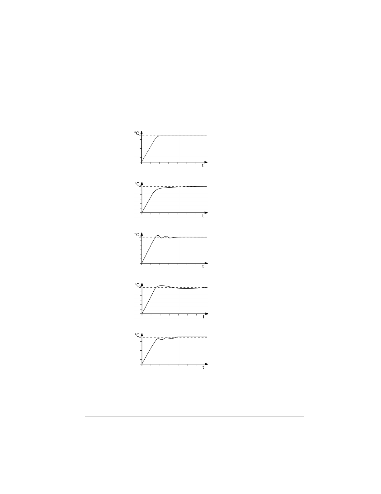
8.6.2 Optimizing temperature curves
The temperature sequence shown on the display provides information about
how individual control parameters can be optimized to achieve a better result.
Operation
Optimal temperature sequence,
temperature quickly reaches the
setpoint without overshooting,
and keeps the setpoint.
Symptom: Temperature sequence
slowly approaches the setpoint
and doesn’t quite reach it.
Solution: Decrease Tv and/or Tn,
increase Xp.
Symptom: Temperature sequence
quickly approaches the setpoint,
but overshoots it and oscillates.
Solution: Increase Tv and/or Tn.
Symptom: Temperature sequence
quickly approaches the setpoint
and overshoots.
Solution: Increase Xp.
Symptom: Temperature sequence
quickly approaches the setpoint,
the temperature builds up and the
setpoint is exceeded.
Solution: Decrease Xp and/or Tv.
63
Find Quality Products Online at: [email protected]
www.GlobalTestSupply.com
Page 64

Operation
8.6.3 Adjust controller
In the menu <Adjust controller> the individual control parameters for
internal and external control can be set.
The device is switched on.
1. Bring up the <Main menu>.
2. From the <Thermodynamics> submenu, select the menu option
<Adjust controller>.
The dialog box for setting the controller appears on the display.
3. Activate internal or external control.
This results in the respective adjustable control parameters. External control
is only possible with an externally connected Pt100 temperature sensor.
4. Switch to the submenu <Control performance>.
5. In the dialog box, set the desired parameters and confirm your entry.
6. For internal control: Activate the aperiodic temperature sequence or the
standard temperature sequence.
The control parameters are set and immediately active.
8.6.4 Limit cooling capacity and heating capacity
In the menu <Limits> the cooling capacity and heating capacity are limited.
The device is switched on.
1. Bring up the <Main menu>.
2. From the <Thermodynamics> submenu, select the menu option
<Adjust controller>.
The dialog box for setting the controller appears on the display.
3. Switch to the submenu <Limits>.
4. In the dialog window that appears, set the limits for cooling capacity and
heating capacity and confirm your entry.
The values are set and are immediately active.
8.6.5 Adjust pump
In the submenu <Adjust pump> the working mode is set, as is the pump
power in one percent increments.
The unit is switched on.
1. Bring up the <Main menu>.
2. From the <Thermodynamics> submenu, select the menu option
<Adjust pump>.
3. Enter the desired value for pump capacity in percent and confirm your input.
64
Find Quality Products Online at: [email protected]
www.GlobalTestSupply.com
Page 65

The minimum value is defined internally. The maximum value is limited to
the adjustable maximum pump power in the menu <Setpoint limits>.
4. Activate the desired pump mode.
The pump is set.
To achieve low setpoint temperatures, it may be helpful to reduce the pump
output in certain situations. This decreases the pump's heat input into the bath
fluid.
8.7 Remote control device
The device can be connected to a PC via its interfaces and controlled remotely
using a program such as ° EasyTemp. It is also possible to send interface
commands to the device using a terminal.
The respective interface is set up when the remote control is deactivated.
If remote control mode is enabled, the device cannot be operated directly.
8.7.1 Remote control device using USB interface
The device can be remote-controlled via the standard USB B interface.
Operation
The device is switched off.
The computer has a terminal program installed.
1. Connect the device (USB plug type B) to the computer with a commercially
available USB cable.
2. Download the suitable USB driver from the download area of the website
Depending on the operating system used by the connected computer, it may
be necessary to install the USB driver.
3. Install the USB driver on the computer.
4. Switch the device on.
5. Call up the <Main menu> on the device.
6. In the submenu <Connect unit>/<Remote control> activate the USB
interface.
The home screen will show USB mode.
7. Start the terminal program on the computer.
8. Use the terminal program to select the COM port of the device and establish
a connection.
Remote control via the USB interface is activated. This is shown with the
“USB” on the home screen. You can now remotely control the device with
interface commands via the computer.
65
Find Quality Products Online at: [email protected]
www.GlobalTestSupply.com
Page 66

Operation
8.7.2 Set RS232 interface parameters
The interface parameters cannot be changed during remote control mode. If
they differ from the factory settings, they must be set before remote control
mode is activated.
Remote control is deactivated.
1. Call up the <Main menu> on the unit.
2. From the submenu <Connect unit>/<Digital interfaces> call up the
menu point <RS232>.
3. Set the interface parameters [Baud rate], [Handshake] and [Parity] if
they differ from the factory settings.
If parity is "None," the number of data bits is set to 8.
The interface parameters are set and immediately active.
8.7.3 Remote control device using RS232 interface
The device can be remote controlled via an optional RS232 interface. A null
modem cable is required to connect to a PC.
The device has an RS232 interface.
The device is switched off.
The computer has a terminal program installed.
1. Connect the device with the computer using a serial interface cable.
2. Switch the device on.
3. Start the terminal program on the computer.
4. Enter the interface parameters into the terminal program.
For the default setting, see the RS232 interface section. The values can be
set in the submenu <Connect unit>/<Digital interfaces>/<RS232>.
5. Use the terminal program to select the COM port of the circulators and
establish a connection.
6. Call up the <Main menu> on the device.
7. Activate the RS232 interface in the <Connect unit>/<Remote control>
submenu.
The home screen will show RS232 mode.
Remote control via the serial interface is activated. This is indicated by an
“R” in the status bar of the home screen. R-OFF appears in standby mode.
You can now remotely control the device with interface commands via the
terminal program.
66
Find Quality Products Online at: [email protected]
www.GlobalTestSupply.com
Page 67

8.7.4 Set EPROG input
The EPROG input can be used to send an external voltage or current signal to
the circulator. Depending on the setting, the circulator interprets the input
signals as a setpoint temperature, power capacity, flow or pressure, and can
output the values as a display on the start screen.
Please note the technical data of the REG/EPROG socket.
The device is switched on.
The remote control mode is deactivated.
The external voltage or current source is connected via the REG/EPROG
socket.
1. Bring up the <Main menu>.
2. Bring up the <Connect unit> submenu.
3. From the <Analog interfaces>/<Analog module> submenu, select the
menu option <EPROG>.
4. Select the input variable Setpoint, Capacity or Flow in the selection window.
If setpoint is selected then the external setpoint values must be set up.
If performance is selected then the actuating variable must be set up.
5. Select the signal type voltage or current.
6. Drive the external voltage/current source to the upper limit value.
The applied voltage or current will be shown as a measurement value.
7. Enter the upper input value and confirm your input.
8. Repeat steps 6 and 7 for the lower limit value.
The EPROG input is set.
8.7.5 Set external setpoint values
By default the setpoint is adjusted on the device or by the programmer. In
addition to this, the device offers the ability to externally specify the setpoint
using the analog REG/EPROG plug or an external Pt100 temperature sensor.
The device is switched on.
The remote control mode is deactivated.
1. Call up the <Main menu>.
2. Call up the submenu <Connect unit> then menu option <External
setpoint>.
3. Select Pt100 or EPROG.
Pt100 can only be selected if an external Pt100 temperature sensor is
connected to the device. The setpoint is then set using the external
temperature sensor.
EPROG can only be selected if the analog option is available and the
setpoint is defined as the input variable in submenu <Analog module>
for EPROG.
The external setpoint value is defined.
Operation
67
Find Quality Products Online at: [email protected]
www.GlobalTestSupply.com
Page 68

Operation
8.7.6 Set up actuating variable
If the device is in remote control mode then the variable (capacity) with which
the cooling unit or heater is controlled can be set using interface commands.
This section describes how the actuating variable can be set.
The device is switched on.
1. Bring up the <Main menu>.
2. From the <Connect unit> submenu, select the menu option <Actuating
variable>.
3. Select Digital or EPROG in the dialog window.
Digital can only be selected if remote control mode is activated.
EPROG can only be selected if the electronic slide-in module with analogue
connections is available and the capacity has been defined as an input
variable for EPROG in the submenu <Analogue module>. The remote
control mode must be deactivated.
The actuating variable is set.
8.7.7 Request device status
The current device status can be queried via an interface command.
The device is connected to a PC via an interface.
1. Enter the command "status“ in the terminal program and press [Enter].
The device responds with a status message. If an alarm or warning is
pending, the device sends the respective alarm or warning message to the
status query. Explanations of the status messages as well as alarm and
warning messages can be found in the Appendix.
8.8 Working with the programmer
Temperature control profiles are defined temperature profiles with a setpoint
temperature as well as a predefined temperature control duration or a
predefined gradient.
The programmer calculates a temperature ramp from these programmed values.
Use the profile timer function to start individual temperature control profiles and
define the number of repetitions. Several temperature control profiles can be
combined into one profile series.
In order for programmed temperature control profiles to run automatically, the
device must remain switched on.
68
Find Quality Products Online at: [email protected]
www.GlobalTestSupply.com
Page 69
NOTE
Falling bath fluid level!
In the case of a prolonged temperature control application, the level of bath
fluid in the bath tank can fall below the alarm limit due to evaporation. A low
liquid level alarm is triggered and temperature control application stops.
• In the event of a prolonged temperature control application, regularly
check the fill level of bath fluid in the bath tank
• If the level is low, refill the bath fluid
Operation
8.8.1 Setting the timer
The timer can be used to program the duration of a tempering from 0 to 999
minutes and to program the start time. The target temperature is set as the
setpoint temperature.
After the set duration has elapsed, the device switches to the previously defined
state:
• Standby mode
• Maintain target temperature
• Temper to original setpoint temperature
The device is switched on.
1. Bring up the <Main menu>.
2. From the <Programmer> submenu, select the menu option <Timer>.
The dialog box for setting the timer appears on the display.
3. Set the start time and the start date and confirm each entry.
4. Set the setpoint temperature and the desired duration, then confirm your
entry.
5. In the <Final state> field, select how the device should behave after the
temperature control expires.
6. Enable the <Active> field to activate the timer.
The timer is programmed and active.
8.8.2 Creating and editing a temperature control profile
Eight individual temperature control profiles can be created with up to 60
individual steps each. The programmer processes the programmed steps of a
temperature control profile according to the specifications.
The device is switched on.
1. Bring up the <Main menu>.
2. From the <Programmer> submenu, select the menu option
<Edit profile>.
69
Find Quality Products Online at: [email protected]
www.GlobalTestSupply.com
Page 70

Operation
3. Select one of the eight profiles and confirm your selection.
The selected profile changes to red.
4. Bring up the <Edit> submenu.
In the dialog window, the selected temperature control profile is displayed
as an editable table with profile number, selected step, and total number of
steps.
5. Press the [Add] softkey to add a new step.
The added step opens as an editable dialog window.
6. Set the setpoint temperature and the duration in hh/mm/ss format or the
gradients in K/min format, and confirm your entry with [OK].
If a gradient is specified, the time specifications are set to zero and vice
versa, since both values are mutually dependent.
7. Press the [Add] softkey to add further steps at the end or the [Insert]
softkey to insert them above the marked line.
8. Edit the values of the newly added steps and confirm each entry with [OK].
9. When you have finished editing the temperature control profile, press the
[Back] softkey to return to the <Edit profile> submenu.
The temperature control profile has been created and saved.
8.8.3 Delete temperature control profile
Existing temperature control profiles can be completely deleted. This deletes all
saved profile data.
The device is switched on.
Temperature control profiles are saved in the <Programmer> submenu.
1. Bring up the <Main menu>.
2. From the <Programmer> submenu, select the menu option
<Edit profile>.
3. Select a temperature control profile and confirm your selection.
The selected temperature control profile changes to red.
4. If you want to delete the selected temperature control profile, press the
[Delete] softkey.
5. Confirm the confirmation prompt with [OK] to delete the temperature
control profile.
The temperature control profile will be deleted. A confirmation message
appears, which must be confirmed with [OK].
The temperature control profile has been deleted.
The [Delete all profiles] softkey can be used to delete all saved temperature
control profiles at once. The procedure is the same as for deleting a single
temperature profile.
70
Find Quality Products Online at: [email protected]
www.GlobalTestSupply.com
Page 71

8.8.4 Set profile timer
Temperature control sequences can be individually programmed for individual
temperature control profiles in the <Profile timer> submenu.
The device is switched on.
1. Bring up the <Main menu>.
2. From the <Programmer> submenu, select the menu option <Profile
timer>.
The dialog box for setting the profile timer appears on the display.
3. Select the <Profile> field.
The display changes to the <Edit profile> submenu.
4. Select a profile.
5. Press the [Back] softkey to return to the <Profile timer> submenu.
The selected temperature control profile is displayed in the dialog window.
6. Set the start time and the start date and confirm each entry.
7. In the <Profile runs> field, set how often the selected temperature control
profile should be repeated.
8. In the <Final state> field, select how the device should behave after the
temperature control sequence expires.
9. Enable the <Active> field to activate the profile timer.
The profile timer is programmed and active.
8.8.5 Profile series setup
The sequence of a profile series is set up in the <Profile series> submenu.
This defines the start time, the number of runs, the frequency, and the behavior
of the device at the end of the profile series.
The device is switched on.
1. Bring up the <Main menu>.
2. From the <Programmer> submenu, select the menu option <Profile
series>.
The dialog box for setting the profile series appears on the display.
3. Select the <Profile> field.
The display changes to the <Edit profile> submenu.
4. Select a profile.
5. Press the [Back] softkey to switch back to the <Profile series> submenu.
The selected temperature control profile is displayed in the dialog window.
6. Set the start time and date, as well as the series end and number of runs.
Always confirm your entry.
7. In the <Weekdays> field, select the days on which the profile series
should run.
Operation
71
Find Quality Products Online at: [email protected]
www.GlobalTestSupply.com
Page 72

Operation
8. In the <Final state> field, select how the device should behave after the
profile series expires.
9. Enable the <Active> field to activate the profile series.
The profile series is programmed and active. It starts at the programmed
start time on the specified start date and runs through the specified number
of temperature control applications on the specified weekdays. At the end
of series production, the device switches to the defined final state.
8.9 Configure signal outputs
8.9.1 Configure signal outputs of the REG/EPROG plug
The REG/EPROG socket provides three channels as signal outputs. The voltage
or current signals emitted via these channels can be externally processed.
The following values can be output:
• Setpoint: Specified setpoint
• Internal: Internal temperature sensor value
• External: External Pt100 temperature sensor value
• Performance: Value of the variable
The device is switched on.
The slide-in module with analog connections is installed.
1. Bring up the <Main menu>.
2. Bring up the <Connect unit> submenu.
3. From the <Analog interfaces>/<Analog module> submenu, select the
menu option <Channel 1…3>.
4. In the drop-down window, select the output variable Setpoint, Internal,
External or Capacity.
5. Enter the lowest output value as the 0 V value.
6. Enter the highest output value as the 10 V value.
7. Repeat steps 5 and 6 for channel 2 and channel 3 respectively.
Channel 3 configures the current output. 0 mA or 4 mA can be selected for
the lowest output value.
The signal outputs of the REG/EPROG socket are configured.
72
Find Quality Products Online at: [email protected]
www.GlobalTestSupply.com
Page 73

8.10 Activating stand-by input
This section describes how standby input can be activated.
The device is switched on.
The electronics slide-in module with analog connections is installed.
1. Bring up the <Main menu>.
2. Bring up the <Connect unit> submenu.
3. From the <Analog interfaces>/<Analog module> submenu, select the
menu option <Standby>.
4. Select Active in the selection window.
The standby input is activated and can be used.
8.11 Adjusting the temperature sensor (ATC)
For physical reasons, there can be a temperature difference in the bath tank
between the temperature sensor and a defined, more remote point within the
bath fluid volume. As a result, the measured temperature deviates slightly from
the actual bath temperature. Adjustment of the temperature sensor can increase
accuracy of the temperature control application.
The adjustment of a temperature sensor requires the determination of the
temperature difference between the temperature sensor and the reference
thermometer. Three adjustment options are available:
• 1-point adjustment: When a sample is tempered to a certain setpoint. The
adjustment curve is displaced parallel to the original curve by the reference
amount.
• 2-point adjustment: When the temperature is controlled between two
setpoints. The slope of the temperature curve is adjusted between two
points.
• 3-point adjustment: When temperature is controlled within a temperature
range. This results in an arched temperature curve.
8.11.1 Adjust internal temperature sensor
This section describes how to adjust the internal temperature sensor of the
device.
The bath tank is filled.
The unit is switched on.
A calibrated reference thermometer is available.
1. Hang the calibrated thermometer in the bath.
2. Bring up the <Main menu>.
Operation
73
Find Quality Products Online at: [email protected]
www.GlobalTestSupply.com
Page 74

Operation
3. From the <Install unit> submenu, select the menu option
<Adjust sensor>.
4. Set the internal mode to inactive.
The input fields are unlocked.
5. Enter the desired setpoint for internal in the first line and confirm your
entry.
6. Enable the number field highlighted in blue on the first line.
The temperature control application starts. Let the reference thermometer
settle for 10 minutes.
7. Enter the measured reference value in the first line in the Cal. column.
8. If necessary, repeat steps 5 to 7 for a 2-point or 3-point adjustment.
9. Activate the mode for the desired number of measuring points and press the
[Save] softkey.
The stored correction values are active immediately.
The internal temperature sensor is adjusted.
8.11.2 Adjust external temperature sensor
Measurable temperature differences can also occur in a connected application.
As with the internal temperature sensor, adjustment of the external temperature
sensor can improve accuracy of the temperature control application.
The unit is switched on.
External control is active.
An external temperature sensor is connected.
The bath tank is at least two thirds full.
A calibrated reference thermometer is available.
1. Hang the reference thermometer in the connected external bath tank.
2. Bring up the <Main menu>.
3. From the <Install unit> submenu, select the menu option
<Adjust sensor>.
4. Set the mode for external to inactive.
The input fields are unlocked.
5. For external, enter the desired setpoint in the first line and confirm your
entry.
6. Enable the number field highlighted in blue on the first line.
The temperature control application starts. Let the reference thermometer
settle for 10 minutes.
7. Enter the measured reference value in the first line in the Cal. column.
8. If necessary, repeat steps 5 to 7 for a 2-point or 3-point adjustment.
9. Activate the mode for the desired number of measuring points and press the
[Save] softkey.
The stored correction values are active immediately.
The external temperature sensor is adjusted.
74
Find Quality Products Online at: [email protected]
www.GlobalTestSupply.com
Page 75

8.12 Device Reset
The function resets the device to the factory settings.
i
The device is switched on.
1. Bring up the <Main menu>.
2. Call up the <Reset device> menu item in the <Install device>
3. If you want to reset the device, confirm the security prompt with [OK].
The device is reset to factory settings.
Operation
submenu.
75
Find Quality Products Online at: [email protected]
www.GlobalTestSupply.com
Page 76

Maintenance
9 Maintenance
9.1 Replace detachable power cord
The device is equipped with a detachable power cord.
If the power cord needs to be replaced, ensure that the new one is at least
dimensioned for the device power requirements. Insufficiently dimensioned
power cords must not be used. See type plate for mains voltage and current
value.
We recommend only using original JULABO spare parts.
9.2 Check safety symbols
The safety labels affixed to the device must be clearly legible at all times. Their
condition must be checked every two years.
1. Check the safety signs on the device for legibility and completeness.
2. Replace defective or missing safety markings.
Safety signs can be reordered from JULABO.
The safety signs on the device have been checked.
9.3 Check the functionality of high temperature cut-off
This section describes how you can test that the high temperature safety
function is operational.
Slotted screwdriver, size 3
The device is switched on.
1. Set the display of the start screen so that it shows the high temperature cutoff value.
2. Use the screwdriver to adjust the overtemperature protection to a
temperature that is below the displayed actual value.
An acoustic signal sounds and the alarm message “Set protective
temperature exceeded” is displayed. The high temperature cut-off works.
3. Then set a value that is above the actual value.
4. Switch the device off, wait a few seconds, then switch the device on again.
The alarm message is deactivated.
5. Set the high temperature cut-off.
The high temperature cut-off is set and its functionality tested.
76
Find Quality Products Online at: [email protected]
www.GlobalTestSupply.com
Page 77
9.4 Test the low liquid level safety function
CAUTION
This section describes how you can test that the low liquid level safety function
is operational.
The device is switched on.
1. Remove the bath lid.
2. Using a long object, e.g. a straightedge, carefully push the thermostat float
downwards until it reaches its mechanical stop.
A beep sounds and the “Tempering fluid level too low” alarm message is
displayed. The low liquid level safety function works.
3. Switch the device off, wait a few seconds, then switch the device on again.
The alarm message is deactivated.
4. Close the bath opening.
The low liquid level safety function has been tested for functionality.
9.5 Emptying
The device must be completely drained if it is to be sent in for technical service
or is to be properly disposed of.
In general, the device should be completely emptied before longer shutdowns or
when there is a change to the external application.
Maintenance
Risk of burns from hot bath fluid!
Bath fluid can become very hot during a temperature control process.
Contact with hot bath fluid can cause scalding.
• Before draining the device, let it cool to room temperature
• Avoid direct contact with hot bath fluid
• Wear protective gloves
The device is tempered to room temperature and switched off.
1. Place an adequately large collection vessel under the drainage valve.
2. Take off the bath lid.
3. Open the drain valve.
The bath fluid drains out of the bath tank into the collection vessel
provided.
4. Once the bath tank is completely drained, close the bath opening.
5. Close the drain valve.
The device is emptied. If an external system is connected, it can now be
disconnected from the device and also drained.
77
Find Quality Products Online at: [email protected]
www.GlobalTestSupply.com
Page 78
Maintenance
NOTE
• Prevent water from entering the device
9.6 Clean device
The circulator and bath tank, and also a cooling machine if connected, should
be cleaned from time to time.
In addition to this, the device must be appropriately decontaminated if
hazardous substances have been spilled on or into the device.
Lint-free cloth
Mild cleaning agent
Damage to the electronics due to water penetration!
Ingress of water can damage electronic components of the device and thus
lead to failure of the device.
• Clean the outside of the device with a damp cloth only
The device is switched off and disconnected from the mains voltage.
1. Allow the device to cool down to room temperature.
2. Completely drain the bath fluid.
3. Clean the surface of the bath tank and the circulator with a damp cloth.
Some dish detergent may also be used for cleaning. If in doubt, ask
technical service for alternative cleaning mediums.
4. Take the venting grid off the cooling machine.
5. Carefully vacuum the dirt off the condenser.
Make sure that the fins of the condenser are not damaged.
6. Place the venting grid back on.
The device has now been cleaned.
78
Find Quality Products Online at: [email protected]
www.GlobalTestSupply.com
Page 79

9.7 Device storage
This section describes how to store the device.
The device is switched off and disconnected from the mains voltage.
1. Empty all system components completely.
2. Clean the device.
3. Carefully dry the device and all its system components, e.g. with
compressed air.
4. Close all connections.
5. Store the device in a dust-free, dry and frost-free location.
The device is protected and can be safely stored there. It can be put into
operation again as needed.
9.8 Technical Service
If the unit shows faults you cannot resolve, please contact our Technical Service.
Before sending a device to Technical Service, the following points must be
observed:
Maintenance
• Clean and decontaminate the device properly to avoid endangering service
personnel.
• Include a brief description of the fault.
• Package the device safely for shipment.
79
Find Quality Products Online at: [email protected]
www.GlobalTestSupply.com
Page 80

Maintenance
9.9 Warranty
JULABO provides a warranty that the device will function perfectly as long as it
is connected and used correctly and as described in the operating manual.
The warranty period is one year from the invoice date.
With the 1PLUS warranty, the warranty can be extended to two years free of
charge.
The 1PLUS warranty gives the user a free extended warranty to 24 months, limit
to a maximum of 10,000 hours of service.
A prerequisite for this is that the user registers the device at
quoting its serial number, within four weeks of initial operation. The warranty
applies from the date of JULABO GmbH’s original invoice.
80
Find Quality Products Online at: [email protected]
www.GlobalTestSupply.com
Page 81

10 Disposal
10.1 Device disposal
When disposing of the device, the applicable country-specific guidelines must be
observed.
The circulator combination is switched off and disconnected from the mains
voltage.
1. Empty the bath tank or cooling machine completely.
2. Disconnect all power cables and, if necessary, data cables from the
circulator and from other connected devices.
3. If present, disconnect the circulator combination from a connected external
application.
4. Remove the circulator from the bath tank or cooling machine.
5. Give the devices to an authorized disposal company.
Disposed of the device in household waste, or similar facilities for the
collection of domestic waste, is not permissible.
The circulator combination is disposed of properly.
Disposal
81
Find Quality Products Online at: [email protected]
www.GlobalTestSupply.com
Page 82
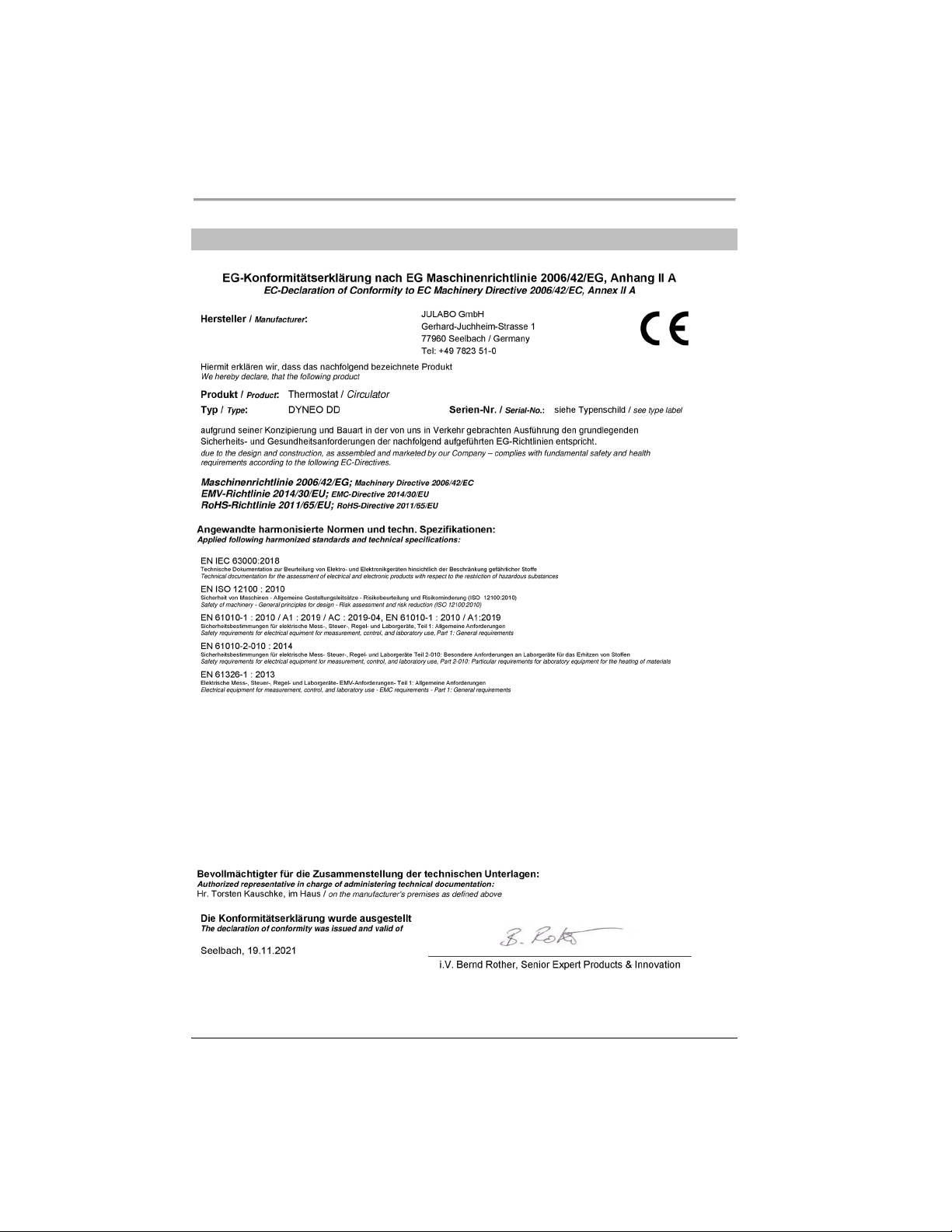
EC Declaration of Conformity
11 EC Declaration of Conformity
82
Find Quality Products Online at: [email protected]
www.GlobalTestSupply.com
Page 83
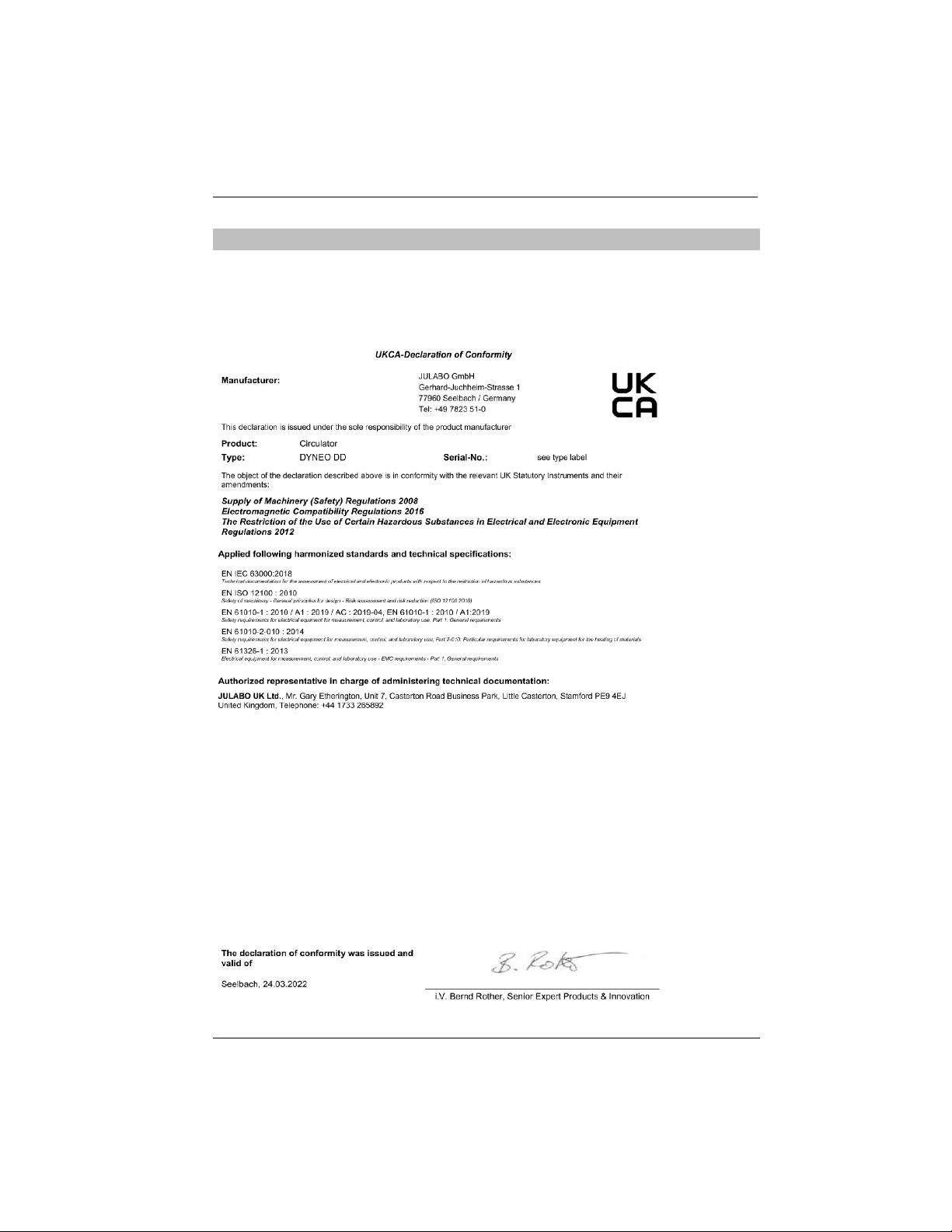
12 UK Declaration of Conformity
UK Office: JULABO UK Ltd., Unit 7, Casterton Road Business Park,
Old Great North Road, Little Casterton, Stamford, PE9 4EJ, United Kingdom,
Tel.: +44 1733 265892
UK Declaration of Conformity
83
Find Quality Products Online at: [email protected]
www.GlobalTestSupply.com
Page 84

Appendix
in_pv_00
in_pv_01
In_pv_02
in_pv_03
in_pv_04
in_pv_06
in_pv_07
in_pv_16
13 Appendix
13.1 Interface commands
Interface commands allow the device to be remote controlled. Parameters can
be retrieved and the current status can be queried. To do this, the device must
be connected to the master computer via a digital interface. Interface
commands are entered using a terminal program.
Interface commands are divided into IN commands and OUT commands.
• IN commands: Retrieve parameters
Command structure: Command +
E.g. Retrieve the setpoint temperature:
IN_SP_00
E.g. Response of the device:
55.5 LF
• OUT commands: Set parameters (only in remote control mode)
Command structure: Command + + Parameter
E.g. Set the setpoint temperature to 55.5 °C:
OUT_SP_0055.5
13.1.1 IN commands
IN commands retrieve device parameters.
Process values System response
Actual value
Current variable (%)
Current temperature of the external Pt100 temperature sensor
Current temperature of the temperature safety sensor
Current setting of the high temperature safety function
Current pressure. EPROG input must be set to pressure
Current flow. EPROG input must be set to flow
Current bath fluid filling level (%)
84
Find Quality Products Online at: [email protected]
www.GlobalTestSupply.com
Page 85

Appendix
in_sp_00
in_sp_03
in_sp_04
in_sp_05
in_sp_06
in_sp_07
in_sp_10
in_sp_11
in_sp_12
1 = psi
in_sp_13
in_sp_27
in_sp_28
in_sp_29
in_mode_01
in_mode_03
in_mode_04
in_mode_05
Setpoints and warning
System response
limits
Set setpoint temperature
Set high temperature warning limit
Set low temperature warning limit
Set working temperature via EPROG
Setpoint temperature set via watchdog function
Set pump stage (1 … 4)
Set actuating variable specification via serial interface
Set temperature unit
0 = °C
1 = °F
Set pressure unit:
0 = bar
Set flow unit:
0 = l/min
1 = gpm
Set pump setting
High temperature alarm limit
Low temperature alarm limit
Device modes System response
Return value 0. The value 0 stands for the control temperature
setpoint as only one temperature setpoint can be set (downward
compatibility for older devices)
Operating mode setting for the EPROG input:
0 = 0…10 V
1 = 4…20 mA
Operating mode setting for the temperature control:
0 = Internal
1 = External
Operating mode set for the temperature control system:
0 = Stop
1 = Start
85
Find Quality Products Online at: [email protected]
www.GlobalTestSupply.com
Page 86

Appendix
in_mode_08
in_mode_11
in_par_00
in_par_01
in_par_02
in_par_03
in_par_04
in_par_05
in_par_06
in_par_07
in_par_08
in_par_09
in_par_10
in_par_11
in_par_12
in_par_13
in_par_14
Set minimum permissible internal temperature InternMin for cascade
in_par_15
in_par_16
Auxiliary parameters
System response
in_hil_00
Set actuating variable limit for cooling capacity (%)
in_hil_01
Set actuating variable limit for heating capacity (%)
Controller dynamics set with internal temperature control:
0 = Aperiodic
1 = Standard
Actuating variable source:
0 = Circulator
1 = Serial
2 = Analog (EPROG)
IN PAR System response
Set sensor difference between working temperature sensor and
safety temperature sensor
Set time constant of the external bath TE
Set internal gradient value SI
Set time constant of the internal bath TI
Set optimization parameter CoSpeed
Ration of cooling/heating capacity pk to ph
Set control parameter Xp of the internal controller
Set control parameter Tn of the internal controller
Set control parameter Tv of the internal controller
Set control parameter Xp of the cascade-controller
Set control parameter Xpu of the subordinate controller (cascade
temperature control)
Set control parameter Tn of the cascade-controller
Set control parameter Tv of the cascade-controller
Set maximum permissible internal temperature InternMax in cascade
temperature control
temperature control
Set band limit upper in cascade temperature control
Set band limit lower in cascade temperature control
86
Find Quality Products Online at: [email protected]
www.GlobalTestSupply.com
Page 87

Appendix
out_sp_00
out_sp_03
out_sp_04
out_sp_06
out_sp_07*
out_sp_10
out_sp_11
out_sp_27
xxx
Pump capacity in %
out_sp_28
out_sp_29
out_mode_01
out_mode_03
out_mode_04
out_mode_05
13.1.2 OUT commands
OUT commands set device parameters. Remote control mode must be active.
Parameter
settings
* Do not use for reprogramming, use out_sp_27 instead. Pump stage 4 has an output pressure of
approx. 450 mbar.
Device modes Parameter Setting
Parameter Setting
xxx.xx Setting for the setpoint temperature
xxx.xx Setting for the high temperature
xxx.xx Setting for the low temperature
xxx.xx Setpoint temperature setting via watchdog function
x Set pump to preset levels 1…5
xxx.xx Setting for the actuating variable via the serial
interface
x Setting the temperature units:
0 = °C
1 = °F
xxx.xx High temperature alarm limit setting
xxx.xx Low temperature alarm limit setting
x Setting 0 (for reasons of downwards compatibility
the parameters 1 or 2 can also be used. Within the
device it has no effect)
x Setting of the operating mode EPROG:
0 = 0-10 V
1 = 0-20 mA
x Setting of the temperature control:
0 = Internal control
1 = External control
x
Start/stop command of the device in remote control
mode:
0 = Stop tempering
1 = Start tempering
87
Find Quality Products Online at: [email protected]
www.GlobalTestSupply.com
Page 88

Appendix
out_mode_08
out_mode_11
out_par_04
out_par_06
out_par_07
out_par_08
out_par_09
out_par_10
out_par_11
out_par_12
out_par_13
out_par_14
out_par_15
out_par_16
x Setting of the internal control dynamic:
0 = Aperiodic
1 = Standard
x Actuating variable source:
0 = Thermostat
1 = Serial
2 = Analog (EPROG)
System parameter Parameter Setting
xxx
Setting the Cospeed control parameter for internal
control
xxx Setting of the control parameter XP for internal
control
xxx Setting of the control parameter TN for internal
control
xxx Setting of the control parameter TV for internal
control
xxx Setting of the control parameter XP of the
subordinate controller (cascade temperature control)
xxx
Setting of the control parameter XPU of the
subordinate controller (cascade temperature control)
xxx Setting of the control parameter TN of the
subordinate controller (cascade temperature control)
xxx Setting of the control parameter TV of the
subordinate controller (cascade temperature control)
xxx Setting of the maximum permissible internal
temperature InternMax in cascade temperature
control
xxx Setting of the minimum required temperature
InternMin in cascade temperature control
xxx Setting of the band limit upper in cascade
temperature control
xxx Setting of the band limit lower in cascade
temperature control
88
Find Quality Products Online at: [email protected]
www.GlobalTestSupply.com
Page 89

Appendix
out_hil_00
out_hil_01
version
status
00 MANUAL STOP
Device in standby mode manual operation
01 MANUAL START
02 REMOTE STOP
03 REMOTE START
-08 INVALID
COMMAND
-09 COMMAND NOT
MODE
-10 VALUE TOO
SMALL
-11 VALUE TOO
LARGE
-13 VALUE EXCEEDS
LIMITS
Auxiliary
Parameter Setting
parameters
-xxx Setting of the actuating variable limit for cooling
capacity (0-100%)
xxx Setting of the actuating variable limit for heating
capacity (0-100%)
13.1.3 Status commands
Status commands are used to query the current status of the device.
Status commands System response
Current firmware version
Return of status, error, warning, alarm
13.1.4 Status messages
Possible status messages from the device for a status query.
Status message Explanation
ALLOWED IN
CURRENT OPERATING
TEMPERATURE
Device in manual mode
Device in standby mode, remote control operation
Device in remote control mode
Device did not recognize the last received command
Last received command is not permissible in the operating mode
The last set value is too small
The last set value is too large
The value is not within the set temperature limits
89
Find Quality Products Online at: [email protected]
www.GlobalTestSupply.com
Page 90

Appendix
13.2 Alarms and Warnings
If the device is connected to a network and remotely controlled, a status query
via interface command will output any pending alarms or warnings as text.
Alarm and warning messages are described in the table.
If a displayed error code is not described in the table or the error is still pending
after switching off and on again, please contact Technical Service.
The listed error codes can occur depending on the device type and version.
-01 The unit is being operated with a bath
-03 The measured temperature is over the
-04 The measured temperature is below
-05 The cable for the working
-06 The temperature difference between
-14
-15 The line of the external temperature
fluid level that is too low.
set high temperature limit.
the set low temperature limit.
temperature sensor has broken or
short-circuited.
the working temperature sensor and
the safety temperature sensor is too
large.
The set protective temperature has
been exceeded.
sensor has short circuited or been
interrupted.
• Top up the bath fluid.
• Check the temperature control hoses
for damage and replace if necessary.
• Increase “high temperature"
temperature limit or decrease
temperature setpoint.
• Reduce “low temperature"
temperature limit or increase
temperature setpoint.
• Contact Technical Service.
• Increase circulation.
• Check the viscosity of the tempering
fluid.
• If the fault has not been remedied,
contact Technical Service.
• Check working temperature range of
the application.
• Increase the value of the protective
temperature or decrease the setpoint
temperature until it is lower than the
set protective temperature.
• Check electrical connection to external
temperature sensor.
90
Find Quality Products Online at: [email protected]
www.GlobalTestSupply.com
Page 91

Appendix
level.
•
Configuration between circulator and
-38
The setpoint value is set to external
temperature sensor, but no signal is
available.
-40 The early warning system for low
liquid level reports a critical fluid
-60 Internal read/write error.
-61 CAN bus error
-62 CAN bus error
-63 Watchdog function has responded.
-70 Units with incompatible
voltage/frequency variants connected
to each other or units incorrectly
configured.
-72
connected refrigeration unit failed.
-83
Excessive power consumption via USB
interface.
-108 The alarm latch of the protective
equipment is still active.
• Check whether an external
temperature sensor is connected or
whether the electrical connection is
interrupted.
• If necessary, adjust the setpoint value.
• Top up the bath fluid.
• Switch off the unit at the mains switch,
wait 4 seconds and then switch the
unit on again.
• Check CAN bus cable for damage and
replace as necessary. Switch the unit
on again. If the fault has not been
remedied, contact Technical Service.
• Alternatively: Deactivate the
refrigeration unit. The circulator
operates as a heater thermostat.
• Switch off unit at mains switch, wait
4 seconds, then switch on unit again.
Switch off the unit at the mains switch,
wait 4 seconds and then switch the
unit on again.
• Check the permissible operating
voltage of the units and their
configuration.
• Switch off the unit at the mains switch,
wait 4 seconds and then switch the
unit on again.
• Check inserted USB stick for defects
and replace as necessary. The USB-A
interface is not suitable for consumers
with a higher required current than the
maximum permissible current.
• Switch off the unit at the mains switch,
wait 4 seconds and then switch the
unit on again.
91
Find Quality Products Online at: [email protected]
www.GlobalTestSupply.com
Page 92

Appendix
-116
The alarm latch of the protective
equipment is still active.
-427
Pressure sensor detects excessive
condensation pressure.
-431 The maximum permissible current
consumption at the compressor has
been exceeded.
-1109 Viscosity of the bath fluid too high or
the circulation rate too low.
-1427 Pressure sensor detects excessive
compensation pressure.
• Switch off the unit at the mains switch,
wait 4 seconds and then switch the
unit on again.
• Check ambient temperature and
reduce if necessary.
• Check condenser for soiling and clean
as necessary.
• Switch off the unit at the mains switch,
wait 4 seconds and then switch the
unit on again.
• For water-cooled units: Check cooling
water temperature and supply.
• If the fault has not been remedied,
contact Technical Service.
• Check mains voltage for nominal
voltage.
• If the fault has not been remedied,
contact Technical Service.
• Check the temperature of the bath
fluid to ensure it is within the desired
temperature range.
• Check ambient temperature and
reduce if necessary.
• Check condenser for soiling and clean
as necessary.
• Switch off the unit at the mains switch,
wait 4 seconds and then switch the
unit on again.
• For water-cooled units: Check cooling
water temperature and supply.
• If the fault has not been remedied,
contact Technical Service.
92
Find Quality Products Online at: [email protected]
www.GlobalTestSupply.com
Page 93

Appendix
-1431
The minimum permissible current
consumption at the compressor has
been fallen short of.
-2426 Evaporation temperature has fallen
below the warning threshold.
• Check mains voltage for nominal
voltage. The specified voltage
tolerance of the unit must not be
exceeded.
• Check the mains cable of the
refrigeration unit for damage and
replace if necessary.
• Check ambient temperature and
reduce if necessary.
• Check CAN bus cable for damage and
replace as necessary.
• If the fault has not been remedied,
contact Technical Service.
• Check pump setting
• Check hose cross-section of connection
to application
• Check that connection to application is
clear
• Check suitability of bath fluid
93
Find Quality Products Online at: [email protected]
www.GlobalTestSupply.com
 Loading...