

Page 1
Immersion / Open Bath / Refrigerated Circulators
Pos: 3 /Technische Dokumentation/Flash CORIO/Einhängethermostat CORIO C/Titelfoto CD @ 0\mod_1395828649188_0.docx @ 4299 @ @ 1
=== Ende der Liste für Textmarke Inhalt1 ===
Operating Instructions
Important: keep original operating manual for future use.
1.953.0800-V8
english
Page 2

Table of contents
1 CORIO® CD product overview ............................................................. 5
2 Intended use ........................................................................................ 5
3 Description ........................................................................................... 6
4 Explanation of safety information ..................................................... 7
4.1 Explanation of other information ............................................................ 7
5 Safety instructions .............................................................................. 8
6 Operator's responsibility - safety instructions ............................... 10
6.1 Requirements for the operating personnel ............................................ 10
6.2 Operating and ambient conditions for using the unit ............................ 10
6.3 Operating the unit ................................................................................. 11
7 Control and function elements......................................................... 13
7.1 Installation of the circulator .................................................................. 16
8 Preparations for operating the device ............................................ 16
8.1 Securing the immersion circulator ......................................................... 16
8.2 Open bath tanks .................................................................................... 20
9 Closed stainless steel bath tanks ..................................................... 22
9.1 Basic refrigeration baths ....................................................................... 22
9.2 Bath fluids ............................................................................................. 24
9.3 Temperature control for external connected systems ............................ 26
9.4 Tubing ................................................................................................... 27
10 Commissioning .................................................................................. 28
10.1 Excess temperature and low level safety devices .................................. 28
10.2 Filling .................................................................................................... 29
10.3 Pump settings ....................................................................................... 30
10.4 Switching on / Start - Stop .................................................................... 30
10.5 Setting the desired temperature value .................................................. 31
10.6 Setting the timer ................................................................................... 31
10.7 ATC - Absolute Temperature Calibration (1-point calibration) .............. 32
10.8 Switch Autostart on and off .................................................................. 33
2
Page 3

CORIO® CD product overview
11 Error messages / Possible causes of faults ...................................... 33
12 Operation of the CORIO CD via the USB interface ......................... 36
13 Emptying the bath tank.................................................................... 38
14 Technical data ................................................................................... 39
14.1 Technical data for circulator .................................................................. 39
14.2 Technical data for refrigeration circulation circulator ............................ 40
14.3 Refrigerant ............................................................................................ 44
15 Materials of parts in contact with the bath fluid ........................... 46
15.1 Circulator .............................................................................................. 46
16 Accessories ........................................................................................ 46
16.1 For external connection ......................................................................... 46
16.2 For open baths ...................................................................................... 46
17 Maintenance, cleaning, storage ....................................................... 47
17.1 Maintain the refrigeration capacity. ...................................................... 47
17.2 Cleaning ................................................................................................ 47
18 Storage .............................................................................................. 48
19 Repair service .................................................................................... 48
19.1 Warranty ............................................................................................... 49
20 Waste disposal .................................................................................. 51
20.1 Packaging.............................................................................................. 51
20.2 Unit ....................................................................................................... 51
20.3 Refrigerant ............................................................................................ 51
Pos: 5 /Technische Dokumentation/Flash CORIO/Einhängethermostat CORIO C/Neue Seite @ 0\mod_1417593782389_0.docx @ 7630 @ @ 1
3
Page 4
The operating manual
Pos: 6 /Technische Dokumentation/Flash CORIO/Glückwunsch - Einleitung @ 0\mod_1395136866201_18.docx @ 4161 @ @ 1
Congratulations.
You have made an excellent choice.
JULABO thanks you for the trust.
This operating manual is designed to familiarize you with the operation
of our units and their possible applications. Please read the operating
manual carefully.
Please call us if you have any questions about the operation of the unit
or about the operating manual.
Contact:
JULABO USA, Inc.
884 Marcon Boulevard
Allentown, PA 18109
Phone: +1(610) 231-0250
Fax: +1(610) 231-0260
info.us@julabo.com
www.julabo.com
The JULABO quality management system
The standards for the development, production and distribution of
temperature control devices for laboratory and industry use satisfy the
requirements of ISO 9001 and ISO 14001.
Registration certificate No. 01 100044846.
Unpacking and inspection
If the packaging is damaged or if you discover any concealed transport
damage when you have unpacked the devices and the accessories,
please notify the supplier in the form of a statement of damage.
• should be kept for future use.
• must be available to operating personnel at all times.
Pos: 7 /Technische Dokumentation/Flash CORIO/CORIO_CD_ GESA MT/CD -Pro duk tübers ic ht @ 0 \mod_1409304670926_18.docx @ 7330 @ 1 @ 1
4
Page 5

CORIO® CD product overview
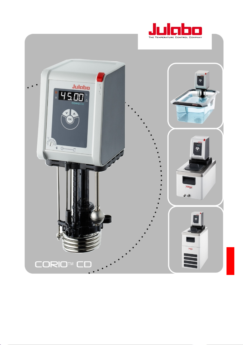
1 CORIO® CD product overview
Immersion
circulator
for bath tanks up to
50 l.
Open bath
circulator
with high quality bath
tanks made of
transparent plastic or
stainless steel.
Bath circulator
for temperate control
in an internal bath or
an external
application.
Refrigerated
circulator
for standard
temperature control
and routine tasks.
Pos: 8 /Technische Dokumentation/Flash CORIO/CORIO_CD_GESAMT/Bestimmungsgemäße Verwendung @ 0\mod_1409218447083_18.docx @ 6620 @ 1 @ 1
2 Intended use
Pos: 9 /Technische Dokumentation/Flash CORIO/Einhängethermostat CORIO C/Neue Seite @ 0\mod_1417593782389_0.docx @ 7630 @ @ 1
JULABO circulators are laboratory devices which are designed for the
temperature control of certain liquid media in a bath tank or with a
refrigeration unit. The bath fluids recommended by JULABO must be
used as tempering media.
Units with pump connections allow the tempering tasks to be carried out
in an external temperature control system.
JULABO circulators are not designed for the direct temperature control of
foods, semi-luxury foods and tobacco, or pharmaceutical and medical
products.
• Direct temperature control means unprotected contact between the
object and the tempering medium (bath fluid).
• The devices are not suitable for use in potentially explosive
environments.
5
Page 6

3 Description
safety instructions at your workstation.
Pos: 11 /Technische Dokumentation/Flash CORIO/CORIO_CD_GESAMT/Verhalten + BA lesen @ 0\mod_1409218461856_18.docx @ 7203 @ @ 1
• These circulators are operated via the splash-proof keypad. The
microprocessor technology allows the setpoint to be set, displayed
and saved using the temperature display LED.
• The PID temperature control automatically adjusts the heat supply to
the requirements in the bath.
• ATC - Absolute Temperature Calibration (1-point calibration)
• The pump function can be switched from internal to external
circulation by a simple switchover button.
• Safety equipment to IEC 61010-2-010:
- Excess temperature protector is a safety device which is
independent of the control circuit whose value is set using a
tool (screwdriver).
- A float switch acts as the low level safety device. If these
safety devices trip, the heater and circulating pump are
completely shut down.
• Interfaces:
- CAN bus to communicate with the refrigeration machine
- USB connector to act as host to update and read data. USB device
for remote control.
It is important to follow these safety instructions to prevent personal
injury and property damage. These instructions apply in addition to the
It is essential that you read the user information before
starting the device.
Pos: 12 /Technische Dokumentation/Flash CORIO/Einhängethermostat CORIO C/Neue Seite @ 0\mod_1417593782389_0.docx @ 7630 @ @ 1
6
Page 7
Explanation of safety information
This signal word designates a danger with a low level of risk which, if it
Designates user tips and other useful information.
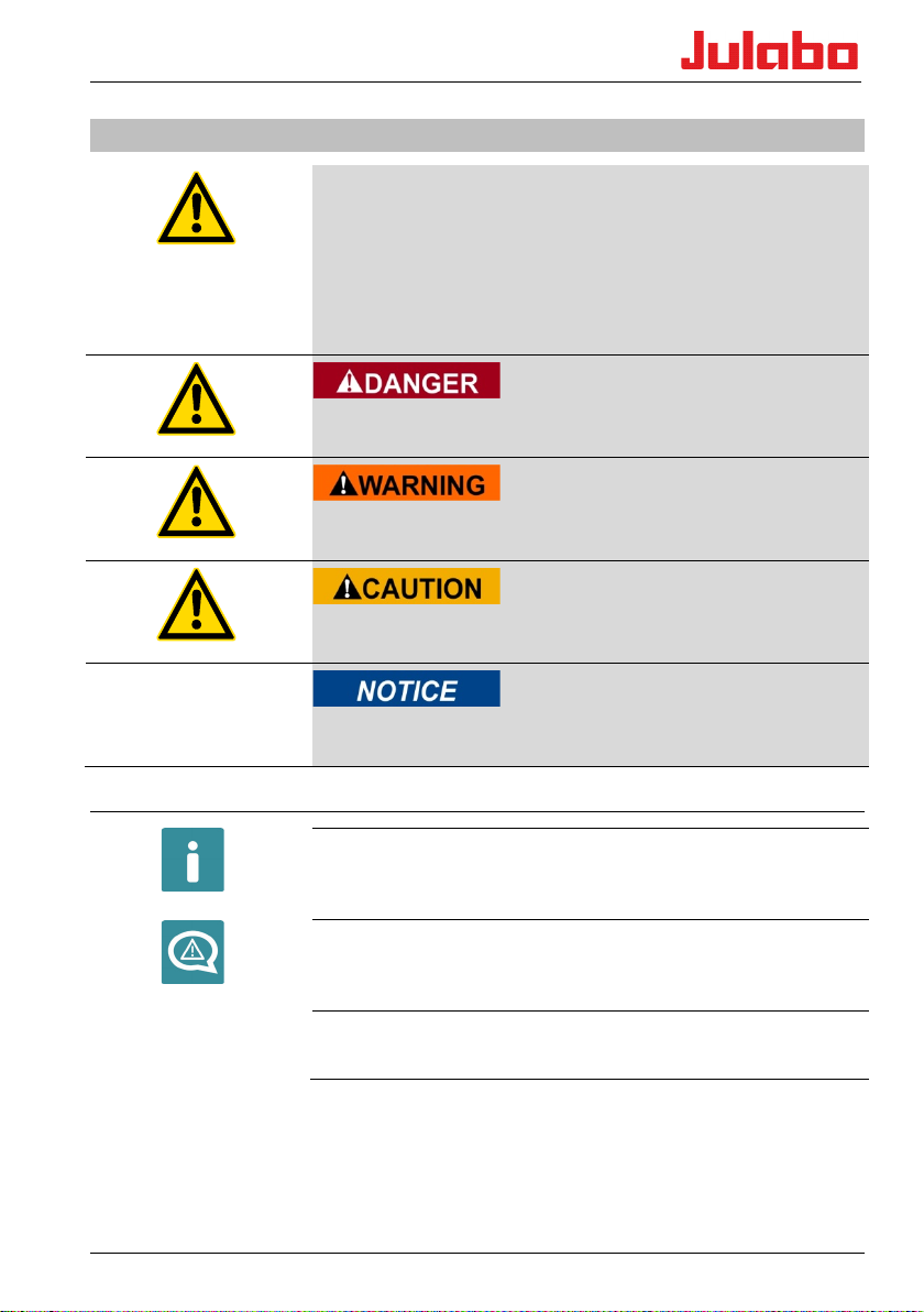
4 Explanation of safety information
The operating manual contains warnings to increase safety when using
the unit. The general warning sign, consisting of an equilateral triangle
surrounding an exclamation sign and reproduced in various signal
colors, is preceded by the signal words.
"Warning of a dangerous situation".
The significance of the danger is classified with a signal word. Read the
instructions carefully and follow them.
This signal word designates a danger with a high level of risk which, if
it not prevented, will result in death or serious injury.
This signal word designates a danger with a medium level of risk
which, if it not prevented, may result in death or serious injury.
not prevented, may result in minor or moderate injury.
Designates a possibly harmful situation. If it is not prevented, the
system or something near it may be damaged.
4.1 Explanation of other information
TIP
Pos: 14 /Technische Dokumentation/Flash CORIO/CORIO_CD_GESAMT/Sicherheitsanweisungen @ 0\mod_1409218454274_18.docx @ 6917 @ 1 @ 1
Your attention is drawn to something special by this.
Dangers at second glance
Designates states which only occur after the start of an action and
could have been prevented if the warning had been heeded.
Informative note
Provides additional information.
7
Page 8

5 Safety instructions
It is important to follow these safety instructions to prevent personal
injury and property damage. These instructions apply in addition to
standard safety practices for working places.
• It is essential that you read the user information before starting the
unit.
• Use PPE (safety gloves, safety shoes, safety goggles).
• Transport the unit carefully. The interior of the unit can also be
damaged by impacts or if it is dropped.
• Do not loiter under the unit during transportation and operation.
• The unit is not intended for use in potentially explosive areas.
• Please observe the specifications for the minimum space
requirement when setting up the unit.
• Only operate the unit in rooms that are well-ventilated, dry and free
of frost.
• Switch the unit off immediately if there is refrigerant leakage.
• Place the unit on a flat surface of non-flammable material.
• Operate the unit under an exhaust hood as much as possible.
• Do not start the unit if it is damaged or leaking.
• Compare the mains voltage and frequency with the specifications on
the type plate.
• Only connect the unit to a fused mains connection via a FI circuit
breaker (Ia=30 mA).
• Only connect the unit to a power socket with ground contact (PE –
protective earth)!
• The power supply plug serves as safe disconnecting device from the
power supply network and must be freely accessible at all times.
• Check the mains cable regularly for signs of damage.
• Do not start the unit if it has a damaged power cable.
• Keep the mains cable away from hot pump connections.
• Refer to the safety sticker. Parts of the unit can be hot or cold.
• Never use the unit without bath fluid.
• Do not reach into the thermal bath fluid.
• Check the filling level of the bath fluid at regular intervals. The pump
and heater must always be completely covered with bath fluid.
• Adjust over-temperature safety device below the flash point of the
bath fluid.
8
Page 9

Safety instructions
• Consider the restricted working temperature range if you are using
plastic bath tanks.
• Monitor the heat expansion of the bath oils as the bath temperature
rises.
• Prevent water getting into hot bath oils.
• Use suitable tubing.
• Secure the tubing connections to prevent them sliding off.
• Do not bend the bath fluid tubing.
• Check the hoses at regular intervals for signs of material fatigue (for
example cracking).
• Do not drain the bath fluid when it is hot.
• Check the temperature of the bath fluid before draining it, for
example by switching on the unit briefly.
• Switch off the unit and pull the plug before moving the unit or
carrying out service or repair work.
• Have all service and repair work carried out by authorized specialists
only.
• Switch off the unit and disconnect it from the power supply before
cleaning it.
• Drain the unit completely before transporting it.
Pos: 15 /Technische Dokumentation/Flash CORIO/Verantwortung des Betreibers Therm. Kl. 3, brennbar @ 0\mod_1395046754147_18.docx @ 4104 @ 1222 @ 1
9
Page 10

6 Operator's responsibility - safety instructions
Products manufactured by JULABO GmbH ensure safe operation when
installed, operated and according to common safety regulations. This
section explains the potential dangers which may occur when operating
the unit and specifies the most important safety measures to prevent
these dangers as far as possible.
6.1 Requirements for the operating personnel
The operator is responsible for the qualifications of the personnel
operating the unit. Ensure that the personnel who operate the unit are
trained in the relevant work application by a trained person.
The operative must receive regular training about the dangers involved
with their work and about action to prevent such dangers.
Ensure that everybody involved with the operation, maintenance and
installation have read and understood the safety information and the
operating manual. The unit may only be configured, installed,
maintained and repaired by trained personnel.
If hazardous substances or substances which may become hazardous are
used, the unit may only be used by a person who is completely familiar
with these substances and the unit. This person must be able to assess
the possible dangers in full.
6.2 Operating and ambient conditions for using the unit
• Avoid impacts on the housing, vibrations, damage to the operative
keypad (keys and display) and heavy soiling.
• Ensure that the product is checked at regular intervals suitable for its
frequency of use to ensure that it is in perfect condition.
• Check the proper condition of the mandatory warning, prohibition,
and safety labels at least every 2 years.
• Ensure that the mains supply has a low impedance to prevent
influencing of other units powered in the same mains.
• The unit is designed for operation in a controlled electromagnetic
environment. This means that in an environment of this nature,
transmission equipment such as mobile phones should not be used
in the immediate vicinity.
• Other units with components which are suceptible to magnetic fields
may be influenced by magnetic radiation. We recommend to
maintain a minimum distance of 1 m.
• Permissible ambient temperature: max. 40 °C, min. 5 °C.
• The relative humidity should not exceed 50 % (40 °C).
• Do not store in an aggressive atmosphere. Protect from dirt.
• Protect from direct sunlight.
10
Page 11
Operator's responsibility - safety instructions
1
2a
2b
6.3 Operating the unit
The bath may be filled with flammable materials. Fire hazard!
Chemical dangers may occur, depending on the bath medium.
Refer to all warnings on the substances used (bath fluids) and in the
relevant instructions (safety data sheets).
The formation of explosive mixtures is possible if the ventilation is
inadequate.
Only use the units in well ventilated areas. The unit is not suitable for
use in potentially explosive environments.
Special substance specifications (bath fluids) must be observed for
correct operation. Caustic or corrosive bath fluids must not be used.
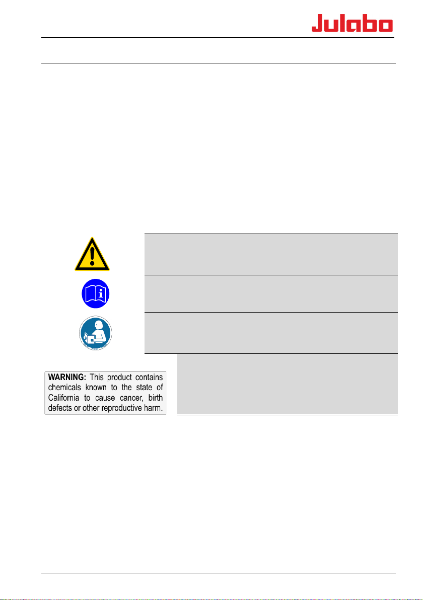
When using hazardous substances or substances which may be
hazardous, the operator must apply the enclosed safety symbols (1 + 2a
or 2b) on the control side panel where they are clearly visible:
Warning of a danger zone. Attention!
Observe documentation. (Operating manual, safety data sheet)
It is essential that you read the user information prior to operation.
Area of validity: EU
3
It is essential that you read the user information prior to operation.
Area of validity: USA, NAFTA
Warning label Proposition 65
11
Page 12

As a result of the wide range of operating temperatures, special care and
caution is essential.
There are thermal dangers: Burns, scalds, hot steam, hot parts and
surfaces which may be touched.
Warning about hot surfaces.
(The label is applied by JULABO)
If external units are connected
Refer to the instructions in the manuals for the external units which you
connect to the JULABO unit, particularly the safety instructions.
The connection assignment of the plugs and the technical data for the
Pos: 16 /Technische Dokumentation/Flash CORIO/CORIO_CD_GESAMT/Bedien- und Funktionselemente CD-300F @ 0\mod_1396265311140_18.docx @ 4387 @ 1 @ 1
products must be observed at all times.
12
Page 13
Control and function elements
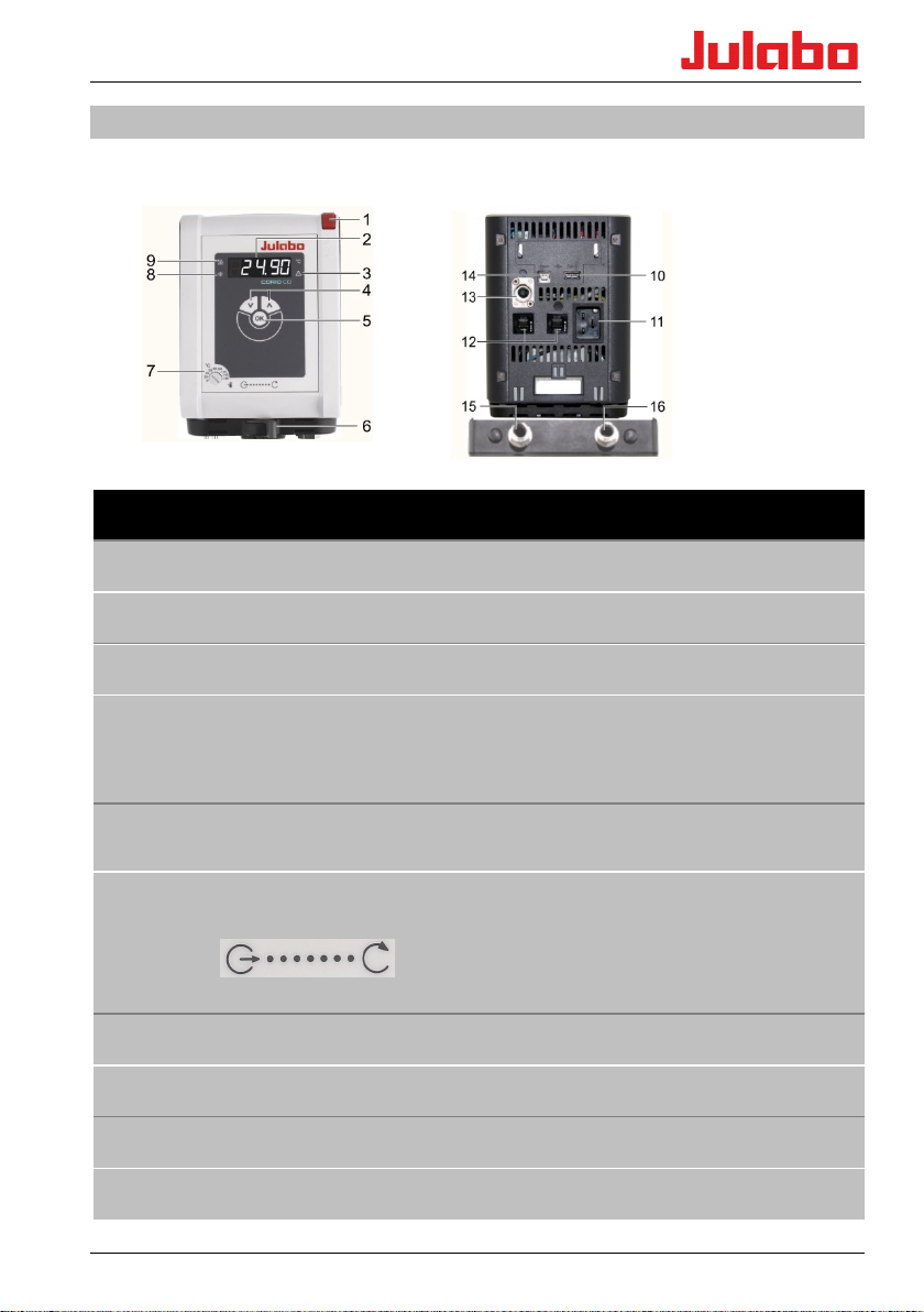
7 Control and function elements
Front Rear
Position Designation
1 Main switch
2 Four-digit temperature display LED, menu display
3 Control indicator - alarm
4 Edit keys
Temperature setpoint increase or decrease
Press the key briefly for step-by-step changes.
Press and hold the key for fast change of setpoint.
5 OK key 1. Switch the device on/off.
2. Store value / parameter.
6 Pump switchover,
Delivery
external…….internal
7 Adjustable excess temperature safety device
8 Control indicator - cooling
9 Control indicator - heating
10 USB host interface (type A)
13
Page 14
11
12 Fuses: Miniature circuit-breaker
13 CAN plug for connecting to the refrigeration machine.
14 USB device interface (type B) for data transfer to the PC, for example for control tasks
15 Pump connection: Return, IN M16x1, external
16 Pump connection: Supply, OUT M16x1, external
Refrigerated Circulators
Mains connection: Integrated connector for voltage supply (mains cable included as
accessory)
using the EasyTEMP software.
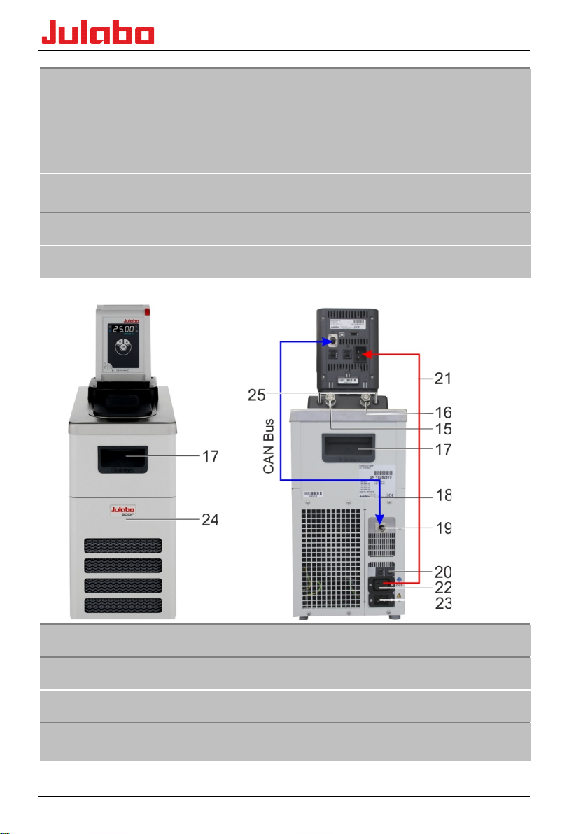
17 Recessed handle (front, rear)
18 CAN connection cable for refrigeration machine circulator
19 CAN plug for connecting to the circulator.
20 Fuses: Miniature circuit-breakers, for refrigeration machine
Resettable fuses for 600F refrigeration units (115 V, 100 V)
14
Page 15

Control and function elements
21 Connection cable: Voltage supply, refrigeration machine circulator
22 Electrical connection: Integrated connector to supply power to the circulator
23
Electrical connection: Integrated connector to supply power to the refrigeration
circulator
24 Drain cock and drain port (behind ventilation grille)
25 Caps (connectors for the cooling coil)
Accessories, included in the supply
1x Main cable for voltage supply for the
refrigeration machine (23) and circulator (11)
(use one only for refrigeration circulator)
1x Connection cable: Refrigeration machine (22) Circulator (11)
1x CAN connection cable (18, for refrigeration machine circulator)
Pos: 18 /Technische Dokumentation/Flash CORIO/CORIO_CD_GESAMT/Aufstellen, Achtung @ 0\mod_1409218443994_18.docx @ 6532 @ 2 @ 1
15
Page 16
• Observe the safety sticker - do not remove!
Only then take the immersion circulator out of the bath tank.
7.1 Installation of the circulator
Danger of scalding due to leaks from the baths
The JULABO plastic baths are not solvent-resistant. JUALBO plastic
bath tanks are for water at a working temperature range from +20°C
to +100°C.
Do not contaminate the bath fluid with solvents.
Things to keep in mind during the installation process:
Risk of tipping due to improper transportation
Crushing, damage to the unit
• Use PPE (safety gloves, safety shoes, safety goggles).
• Carry the unit with 2 persons (see the Technical Data for the
weight).
• Transport the unit carefully on firm, level ground. The interior of
the unit can also be damaged by impacts or if it is dropped.
• Do not loiter under the unit during transportation and operation.
• The installation site should be a sufficiently large room to ensure
that it does not become too hot due to the heat emission.
• The surface for the device should be flat and made of nonflammable material.
• A specific room size is prescribed for refrigerated circulators.
• At high temperatures, position the unit under an exhaust hood as
much as possible due to potential vapors from the thermal bath
fluid.
Pos: 20 /Technische Dokumentation/Flash CORIO/CORIO_CD_GESAMT/Befestigen, Einhängethermostat @ 0\mod_1409218444321_18.docx @ 6543 @ 12 @ 1
8 Preparations for operating the device
8.1 Securing the immersion circulator
Danger of electric shock.
• Carefully secure the immersion circulator on the bath vessel.
Poorly installed circulators can fall into the bath tank.
• Have the unit checked by a service technician prior to re-use.
• The heater must not be in contact with the wall or the
bottom of the bath tank. Minimum distance 15 mm.
• Pull the plug to disconnect the unit from the power supply.
16
Page 17

Preparations for operating the device
A range of accessories is available for various applications:
• Bath clamp (for securing the circulator to baths)
• Bracket (for securing the circulator to JULABO refrigeration
machines)
• Pump set (for connecting external applications)
• Cooling coil (for operating close to ambient temperature)
• Stand holder with rod (for securing to a laboratory stand)
Bath attachment clamp, order No. 9970420
• Pay special attention to the circulator's immersion depth (see
Technical data) when selecting the bath.
• Place the bath on a flat surface on a pad made of non-flammable
material.
• Secure the bath attachment clamp to the bath tank. The wall
thickness may be up to 30 mm.
• Attach the circulator with a “click” to the bath attachment clamp.
Pos: 21 /Technische Dokumentation/Flash CORIO/CORIO_CD_GESAMT/Stativhalterung @ 0\mod_1422285260352_18.docx @ 7820 @ @ 1
Pos: 22 /Technische Dokumentation/Flash CORIO/CORIO_CD_GESAMT/Montageaufsatz @ 0\mod_1422270519338_18.docx @ 7810 @ @ 1
Stand attachment, order No. 9970022
For use with glass tanks a stand attachment with rod is available as an
optional accessory.
The circulator must be mounted vertically and secured against rotation.
If necessary, secure the nuts of the rod also.
17
Page 18

Bracket, order No. 9970177
Installation on the circulator
• Slide the bracket over the heater and pump on to the circulator
• Push the end of the tubing on the "OUT" side on to the outlet port
on the pump.
• Secure against slipping using the spring steel clamp.
• Push the end of the tubing on the "IN" side into the holding
device on the pump.
• Secure the bracket housing to the base of the circulator using the
four screws.
Connect an external system
• Remove the union nuts and sealing plates from the pump
connectors.
• The tubing connections can be used for hoses with M16x1
connections in this state.
Or:
• Secure barbed fittings to the union nuts.
• Connect tempering hoses and secure them with tube clamps to
prevent them sliding off.
• Connect the tubing for the supply and return to the pump
connectors and the external consumer and secure them with tube
clamps.
• Switch the pump function to external circulation.
Pos: 23 /Technische Dokumentation/Flash CORIO/CORIO_CD_GESAMT/Pumpenset @ 0\mod_1409218453557_18.docx @ 6884 @ @ 1
Pump set, order No. 9970140
Installation on the circulator
• Push the end of the tubing on the "OUT" side on to the port on
the pump.
• Secure against slipping using the spring steel clamp.
• Push the end of the tubing on the "IN" side on to the holding
device on the pump.
• Secure the pump housing to the base of the circulator using the
two screws.
• Attach the circulator to the bath clamp.
The total immersion depth will be reduced due to the pump set.
18
Page 19

Preparations for operating the device
Connect an external system (also applies to bracket)
• Remove the union nuts and sealing plates from the pump
connectors.
• The hose connectors can be used for tubing with M16x1
connections in this state.
Or:
• Secure barbed fittings to the union nuts.
• Connect tubing and secure them with tube clamps to prevent
them sliding off.
• Connect the tubing for the supply and return to the pump
connectors and the external consumer and secure them with
tube clamps.
• Switch the pump function to external circulation.
Pos: 24 /Technische Dokumentation/Flash CORIO/CORIO_CD_GESAMT/Kühlschlange Corio CD @ 0\mod_1409218451357_18.docx @ 6796 @ @ 1
Cooling coil, order No. 9970100
A cooling coil is required for working at around ambient temperature
(20 °C) A cooling water flow rate of 45 ml/min is generally sufficient to
compensate for the intrinsic temperature.
The cooling water temperature should be at least 5 °C lower than the
working temperature.
Install the cooling coil on the pump set
• Remove the caps from the pump set.
• Insert the ends of the cooling coil through the fastening boreholes
and secure them with the washers and hex nuts.
• Install the connection ports to the cooling coil.
• Slide the cooling water hoses over the connection ports and
prevent slipping.
Bracket with cooling coil, order No. 9970176
Install the cooling coil on the bracket
• Remove the caps from the bracket.
• Slide the ends of the cooling coil through the fastening boreholes.
• Secure them with the washers and hex nuts.
• Install the connection ports to the cooling coil.
• Slide the cooling water tubing over the connection ports and
prevent slipping.
Pos: 25 /Technische Dokumentation/Flash CORIO/CORIO_CD_GESAMT/Offene Badgefäße (bxhxt) @ 0\mod_1424251016879_18.docx @ 7860 @ 2 @ 1
19
Page 20

+20 ... +100
1.2
1.5
2.3
2.7
23 x 38 x
38
32 x 38 x 38
38 x 58 x 38
38 x 58 x 43
15 x 15 x
23 x 15 x 15
30 x 35 x 15
30 x 35 x 20
3.5 …5.0
6.0 … 9.0
14.0 … 19.0
20.0 … 27.0
* With CORIO circulators
2.6
5.2
6.1
6.9
23x38x41
38x40x42
38x40x47
38x58x42
15x15x15
30x18x15
30x18x20
30x35x15
8.2 Open bath tanks
Open JULABO baths can be combined with JULABO circulators from the
CORIO product series. When combined with these circulators they are
designed for controlling the temperature of liquid media recommended
by JULABO.
The circulators are mounted on the baths using bath attachment clamps,
for example.
Technical details for transparent bath tanks
Type BT5 BT9 BT19 BT27
Order numbers 9901305 9901309 9901319 9901327
Temperature range °C
Approx. weight kg
Dimensions (WxDxH*) cm
Useful bath opening
(WxLxD)
cm
15
Filling volume, Min...Max l
Material
Parts in contact with the bath fluid: Polycarbonate
Technical details for stainless steel bath tanks
Type B5 B13 B17 B19
Order numbers 9903405 9903413 9903417 9903419
Temperature range °C
+20 ... +150
Approx. weight kg
Dimensions (WxDxH*) cm
Useful bath opening
(WxLxD) cm
Filling volume, Min...Max l
Material
3.5 ... 5.0 9.0 ... 13.0 13.0 ... 17.0 14.0 … 19.0
Parts in contact with the bath fluid: Stainless steel
20
Page 21

Preparations for operating the device
+20 ... +150
8.0
17.6
14.6
38x58x47
91x36x43
54x34x57
30x35x20
66x32x15
33x30x30
17.0 …
27.0
26.0 … 39.0
35.0 …41.0
* With CORIO circulators
Type B27 B33 B39
Order numbers 9903427 9903433 9903439
Temperature range °C
Approx. weight kg
Dimensions (WxDxH*) cm
Useful bath opening
(WxLxD) cm
Filling volume, Min...Max l
Material
Parts in contact with the bath fluid: Stainless steel
Bath covers
Order No. Designation For Baths
9970296
Flat stainless steel bath cover B5
9970290 Flat stainless steel bath cover B13, B17
9970291 Flat stainless steel bath cover B19, B27
9970292 Flat stainless steel bath cover B33
9970293 Flat stainless steel bath cover B39
9970254 Lift-up stainless steel gable cover B19, B27, BT19, BT27
9970257 Lift-up stainless steel gable cover B33
Pos: 26 /Technische Dokumentation/Flash CORIO/CORIO_CD_GESAMT/Geschlossene Badgefäße (bxhxt) @ 0\mod_1424253291718_18.docx @ 7871 @ 1 @ 1
21
Page 22

9 Closed stainless steel bath tanks
Intended use
JULABO BC4, BC6, BC12 and BC26 closed stainless steel baths can be
combined with JULABO circulators from the CORIO product series. When
combined with these circulators they are designed for controlling the
temperature of JULABO recommend liquid media.
Technical details for the sealed baths
The circulators feature the bracket which is secured to the
baths.
Type
Order No.
Temperature range °C +20…+150
Approx. weight kg 5.2 6.4 8.2 15.0
Dimensions (WxDxH*) cm 23x41x42 24x44x47 33x49x47 39x62x48
Useful bath opening
(WxLxD), inner cm 13x15x15 13x15x20 22x15x20 22x30x20
Filling volume
Min. … Max.
Materials for parts in
contact with the
medium
l
* / With circulator
BC4 BC6 BC12 BC26
9905504 9905506 9905512 9905526
3.0…4.5
Bath and drain cock: 1.4301 / 304H
Bath/Bath cover seal: FKM Viton®
O-ring on drain cock: FKM Viton®
4.5…6.0 8.5 … 12.0 19.0 …26.0
9.1 Basic refrigeration baths
Intended use
The basic refrigeration baths can be combined with JULABO circulators
of the CORIO product series. In combination with these circulators, they
are intended for the temperature control of liquid media (bath fluids).
22
Page 23

Closed stainless steel bath tanks
Type
Order No.
Temperature range °C -20…150 -20…150 -25…150 -35…150
Weight kg 26,0 25,0 28,0 36,0
Dimensions (WxDxH*) cm 23x39x65 44x41x44 24x42x66 33x47x69
Useful bath opening
(WxLxD), inner cm 13x15x15 13x15x15 13x15x15 22x15x15
Filling volume
Min. … Max.
Materials for parts in
contact with the
medium
Type
Order No.
Temperature range °C -40…200 -40…200 -40…150
Weight kg 36,0 52,0 49,0
Technical details for basic refrigeration baths
The bracket is required for installation on the circulator.
200F 201F 300F 600F
9461701 9461702 9461703 9461704
l
3,0…4,0
Bath and drain valve: 1.4301 / 304H
Bath/Bath cover seal: FKM Viton®
O-ring on drain valve: FKM Viton®
601F 900F 1000F
9461705 9461706 9461707
3,0…4,0
3,0 … 4,0
5,0 …7,5
Dimensions (WxDxH*) cm 36x46x74 39x62x75 42x49x70
Useful bath opening
(WxLxD), inner cm 22x15x20 26x35x20 22x15x15
Filling volume
Min. … Max.
Materials for parts in
contact with the
medium
l 8,0…10,0 21,0…30,0
Bath and drain valve: 1.4301 / 304H
Bath/Bath cover seal: FKM Viton®
O-ring on drain valve: FKM Viton®
* / with circulator
5…7,5
23
Page 24

9.2 Bath fluids
•
Pos: 30 /Technische Dokumentation/Flash CORIO/CORIO_CD_GESAMT/Temperierflüssigkeiten, Ungeeignete - SHKL 3 @ 0\mod_1409218457441_18.docx @ 7038 @ @ 1
fluid is used.
• Only use thermal oils which are recommended by JULABO. The
viscosity of the oil is tailored to the pump capacity.
• Refer to the safety data sheet of the bath fluid, particularly its
flash point.
• Set the excess temperature protector correctly.
Always store bath fluid so that it cannot harm the environment.
Danger of burns and property damage if unsuitable bath
There is a selection of recommended bath fluids on the JULABO
homepage at www.julabo.com. Do not exceed the maximum viscosity of
2
50 mm
/s when you select your product.
Water as the bath fluid
If you use water as the bath fluid
Recommended water mixture:
70 % soft/decalcified water and 30 % tap water for a temperature
range from 5 °C to 80 °C.
The parts of the bath which come into contact with the bath fluid
may be damaged and cause the failure of the device.
The water quality depends on the local conditions.
• Hard water is not suitable for temperature control tasks due to
its high lime content and will produce lime deposits in the bath.
• Ferrous water can cause corrosion, even on stainless steel.
• Chloric water can cause pitting corrosion.
• Distilled and deionized water is not suitable. Their specific
properties cause corrosion in the bath, even on stainless steel.
Check the quality of the water you use at regular intervals.
Evaporation and constant refilling may produce a concentration
of harmful substances in the bath.
You should therefore check the quality of the water in the bath
at regular intervals.
Replace the water in the bath in full at regular intervals.
24
Page 25

Closed stainless steel bath tanks
Pos: 31 /Technische Dokumentation/Flash CORIO/CORIO_CD_GESAMT/Indirekt temperierte Flüssigkeit -Vorsicht - @ 0\mod_1409218450811_18.docx @ 6774 @ @ 1
Pos: 32 /Technische Dokumentation/Flash CORIO/CORIO_CD_GESAMT/Temperiersystem, extern, Pumpenset @ 0\mod_1409218458486_18.docx @ 7082 @ 2 @ 1
Unsuitable bath fluids.
JULABO cannot accept any liability for damage caused by the selection
of an unsuitable bath fluid.
Unsuitable products include bath fluids which
• are highly viscous (much higher than recommended at the
relevant working temperature).
• tend to crack.
• have a toxic, caustic or corrosive effect.
Properties of indirectly temperature-controlled fluids and
substances
The intended use of the units includes the indirect temperature control
of fluids.
We do not know which substances these are.
Many substances are:
• inflammable, flammable or explosive
• harmful
• polluting
In other words: dangerous
The user bears sole responsibility for handling these substances!
Use personal protective equipment!
The following questions should help to identify possible dangers and
minimize risk.
• Are hazardous vapors or gases produced when heated?
Does operation of the bath has to be conducted in a fume hood?
• What should you do if a dangerous substance has been spilled on
or in the device?
Obtain information on the substance before starting work and
define a decontamination method.
• Are all hoses and electrical cables securely connected and routed?
Keywords: Sharp edges, hot surfaces during operation, moving
machine parts, etc.
25
Page 26

9.3 Temperature control for external connected systems
Danger from the incorrect use of external connected
systems.
Unsuitable materials may cause the failure of the system.
Check the externally connected systems for the
following:
• Compression strength.
• Corrosion resistance.
• Check the materials used for parts in contact with the medium.
The circulator is designed for the temperature control of external
connected systems (temperature control system).
Connect an external system
Remove the union nuts and sealing plates from the pump connectors.
The tube connectors can be used for tubing with M16x1 (internal)
connections in this state.
Tighten the connections with a maximum torque of 3 Nm, holding the
nuts (a.f. 17 mm) as you do so.
Second method
Secure barbed fittings to the union nuts. Tighten the connections with
a maximum torque of 3 Nm, holding the nuts (a.f. 17 mm) as you do
so.
Connect tubing and secure them with tube clamps to prevent them
sliding off.
Connect the tubing for the supply and return to the pump connectors
and the external consumer and secure them with tube clamps.
Switch the pump function to external circulation.
26
Page 27

Closed stainless steel bath tanks
9.4 Tubing
Danger of injury from defective tubing.
The bath fluid tubing is a potential source of danger at high working
temperatures. Large volumes of hot bath fluids can be pumped out of a
damaged tubing in a short period of time.
Possible consequences:
• Skin burns
• Breathing problems due to the hot atmosphere
Danger from unsealed pump connections.
• If the pump connections are not sealed, bath fluid may be pumped
out without any control.
• Set the lever on the pump to internal circulation.
• Unused pump connections must always be sealed with sealing
screws.
Danger from the incorrect use of tubing.
• The tubing must be suitable for the pressure and temperature range
which results from operation and for the bath fluid (for example
silicon oil must not be used with silicon tubings).
• Secure the tubing connections to prevent them sliding off. Use tube
clamps.
• Do not kink the tubing. This will reduce throughput and may cause
the maximum pressure in the system to be exceeded (glass
reactor). The tube length should therefore be kept at a reasonable
level.
• Prepare a maintenance plan.
Check tubing at regular intervals, at least once per year, for signs
of material fatigue (for example cracking)
The tubing must be replaced at regular intervals if they are in
constant use.
We recommend that you select suitable tubing on the JULABO
homepage.
Pos: 34 /Technische Dokumentation/Flash CORIO/CORIO_CD_GESAMT/Inbetriebnahme - Netzspannung, ausführliche Warnung @ 0\mod_1409218450561_18.docx @ 6763 @ 1 @ 1
27
Page 28

10 Commissioning
Commissioning the circulator with a refrigeration machine
Connect the circulator and refrigeration machine using the mains lead.
Connect them to the voltage supply using the fitted plug on the
refrigeration machine and the mains lead. Connect the CAN jacks on
Pos: 35 /Technische Dokumentation/Flash CORIO/Warnung heiße Oberfläche @ 0\mod_1389686088320_18.docx @ 3668 @ @ 1
both devices with the CAN connection cable to transfer data.
Danger from mains voltage.
Risk of injury from electric power.
• Compare the mains voltage and frequency with the details on the
model plate.
• Connect the device only to a safe power supply via FI-circuit
breaker (IA = 30 mA).
• The device may only be connected to power outlets with a ground
contact (PE – protective earth).
• The mains plug serves as a safe disconnecting device from the
power supply network and must be freely accessible at all times.
• Do not start the device if it has a damaged mains cable.
• Check the mains cable regularly for signs of damage.
• We disclaim all liability for damage caused by incorrect line
voltages!
Cold or hot device surfaces
Frostbit or burns
What should be observed when operating the JULABO
temperature control unit?
• Unit parts may develop high surface temperatures. A hot surface
means it has a temperature of 60 °C / 140 °F or more.
• Let the device cool down to an uncritical safe temperature.
• Use safety gloves.
Pos: 36.1 /Technische Dokumentation/Flash CORIO/Schutzeinrichtung, Übertemperatur, Unterniveau - Erklärung @ 0\mod_1389688531828_18.docx @ 3728 @ 2 @ 1
10.1 Excess temperature and low level safety devices
The safety devices are not affected by the control circuit. When they trip
all actors are permanently shut down.
The alarm is displayed optically and acoustics with a continuous signal
Pos: 36.2 /Technische Dokumentation/Flash CORIO/Übertemperatur-, Unterniveau-Schu tzeinrichtung -Warnung @ 0\mod_1389688599281_18.docx @ 3734 @ @ 1
28
tone and the reason for the alarm is shown on the display as a number.
Page 29

Commissioning
signal tone will sound.
Danger from damaged safety devices
Possible serious consequences for personnel and working areas.
Check the safety devices at least twice per year.
Excess temperature protector, IEC 61010-2-010
Turn the adjustable excess temperature protector to the cut-out point
(actual temperature) using a screwdriver. The actors will be shut down
on all poles, the circulator will show error message E 14, the "Alarm"
+ +
E 14
control display will be lit and a continuous signal tone will sound.
Low level safety device, IEC 61010-2-010
The float switch in this device must be moved manually in the bath to
test the function, for example using a screwdriver.
Push down the float until its reaches the mechanical stop.
The actors will be shut down on all poles, the circulator will show error
message E 01, the "Alarm" control display will be lit and a continuous
Pos: 37 /Technische Dokumentation/Flash CORIO/CORIO_CD_GESAMT/Füllen - Grundlegende Gefahren @ 0\mod_1409218449251_18.docx @ 6708 @ 2 @ 1
10.2 Filling
Pos: 39 /Technische Dokumentation/Flash CORIO/CORIO_CD_GESAMT/Pumpeneinstellung @ 0\mod_1409218452964_18.docx @ 6873 @ 2 @ 1
Basic dangers.
The volume of oil used as bath fluid changes with the temperature.
Starting from the volume when the bath is filled (room temperature) it
may increase or decrease during operation.
The bath temperature rises - hot bath fluid can overflow.
The bath temperature falls - the low level alarm will stop the tempering
process.
Monitor the level until it reaches working temperature.
Filling process
• Ensure that the drain valve is closed. Turn the knurled screw.
• Carefully insert bath fluid - never allow bath fluid to get inside the
circulator.
• Do not exceed the maximum bath capacity (see Technical Data).
• 1 - The bath temperature rises - hot bath fluid can overflow.
• 2 - The bath temperature falls - the low level alarm will stop the
tempering process.
• Monitor the level until it reaches working temperature.
29
Page 30

through adjustment.
OFF
Start
indicator has stopped flashing.
10.3 Pump settings
To meet all the requirements for internal and/or external temperature
control tasks, the direction of the pump flow is continuously
adjustable.
For this purpose the lever below the head of the circulator can be
adjusted from:
1.) Max. internal pump flow to...
2.) Max. external pump flow.
Risk of burns due to hot bath fluid
When adjusting the pump flow, make sure that no bath fluid is spilled
from the bath opening due to circulation. For internal temperature
control (external pump connections closed), the adjusting lever is to
be set first to reduced internal circulation (2) before the circulator is
started. After starting the circulator, circulation can be optimized
Pos: 40 /Technische Dokumentation/Flash CORIO/Einschalten/Start-Stopp @ 0\mod_1395238575986_18.docx @ 4209 @ 2 @ 1
10.4 Switching on / Start - Stop
28.35
When pressing the keys, it is advisable to hold the
circulator head with one hand.
Switching on
• The device is switched on by pressing the power switch (1).
The unit performs a self-test. All the segments of the four
digit LED temperature display will illuminate.
The "OFF" signal then indicates that the unit is ready to
operate.
• Press OK for approx. 1 second.
The current bath temperature will be shown on LED
temperature display.
Stop
• Press OK for approx. 1 second.
• Switch off the unit with the circulator's mains power switch.
In combination with the cold bath base units 600F, 601F,
900F, 1000F, the flashing control indicator "Cooling" after
temperature regulation is complete indicates that a valve is
still open. Only turn off the main power switch after this
30
Page 31

Commissioning
The temperature can be set when the device has been started or
Pos: 41 /Technische Dokumentation/Flash CORIO/CORIO_CD_GESAMT/Temperatur-Sollwerteinstellung @ 0\mod_1409218455522_18.docx @ 6961 @ 22 @ 1
10.5 Setting the desired temperature value
Factory setting: 10 °C
Example:
Changing the desired value from
33.00 to 45.50
stopped.
The set value is saved so that it will be retained even after a
power outage.
1.
Press the edit key or briefly to switch from
displaying the actual value to the desired value. The
digits before the decimal point flash.
Change the value:
2.
Press the key to set a higher value.
Press the key to set a lower value.
Press the key briefly for single steps, press and hold the
key to adjust the values quickly.
Save the set value as the desired value by pressing the
3.
key. The digits after the decimal point flash.
Change the value:
4.
Press the key to set a higher value.
Press the key to set a lower value.
Press the key briefly for single steps, press and hold the
key to adjust the values quickly.
Save the set value as the desired value by pressing
5.
.The new desired value will flash three times.
10.6 Setting the timer
Timer displays
Timer set to 15 minutes.
The timer keeps the set value for a defined period of time. The
device then stops (OFF). The timer settings can be set when the
device has been started or stopped.
The set value is saved so that it will be retained even after a
power outage.
Setting the timer
1. and simultaneously press “
on the display.
2. Changing the timer value (in minutes):
Press the key to set a higher value.
Press the key to set a lower value.
Press the key briefly for single steps, press and hold the
key to adjust the values quickly.
3. Save the set value as the desired value by pressing .
The new timer value will flash three times.
t” and O. appear
31
Page 32

The decimal point flashes until the desired value (±0.1 K) is
If the value is outside a window of
Error message:
28 seconds until the timer ends
/Technische Dokumentation/Flash CORIO/CORIO_CD_GESAMT/ATC - CD @ 1\mod_1432892086111_18.docx @ 8260 @ 2 @ 1
10.7 ATC - Absolute Temperature Calibration (1-point calibration)
1-point calibration:
50.0
50
.00
48.90
CAL
- Err
reached. After the desired value is reached, the timer starts and
the display alternates between the actual temperature (for 3 sec.)
and the remaining time (for 2 seconds). The remaining time < 1
min is displayed in seconds. Until the desired value is reached, it
can still be changed. The timer remains active and will start when
the new desired value is reached. If the desired value is changed
while the timer is running, the timer will be deactivated. After the
set time elapses, a beep sounds twice and the device goes into
OFF state.
the
Stopping the timer
• Press the key for about 1 sec. - OFF.
The temperature sensor can be calibrated at any value in the working
temperature range.
Place a calibrated thermometer (resolution: 0.01°C) in the center of the
bath to measure the actual bath temperature.
1st Switch on the circulator at its mains switch
2nd Set the required calibration value as described in "Adjusting
temperature setpoint" (example: 50.00 °C).
3rd Start the unit:
Press the key.
4th The bath will be heated to 50.00°C.
When the setpoint is reached, allow the bath temperature to settle
for approx. 3 minutes.
5th Start the calibration:
Press the “Service” and the key together until the comma in
the display starts to flash.
6th Read the bath temperature value on the calibrated
thermometer and round it up or down and set it.
(Example: 48.87 °C to 48.90 °C)
7. Press the key to confirm.
7th The circulator will confirm the process by displaying "CAL".
±5°C, its entry will be ignored!
Err = Error
32
Page 33

Error messages / Possible causes of faults
•
1
2
The switchover process is
Autostart on
Autostart off
10.8 Switch Autostart on and off
The AUTOSTART function allows the device to be started as soon as the
main switch is pressure, which in turn allows you to use a timer.
Uncontrolled device start
If circulators are started using "AUTOSTART", ensure that even if it is
started accidentally, for example after a power outage, it does not pose
a danger to personnel or equipment.
Ensure that the circulator's safety equipment is set correctly.
. Press and hold the key and
+
. switch on the circulator using the main switch.
shown briefly on the temperature display LED.
AOn
AOFF
Pos: 44 /Technische Dokumentation/Flash CORIO/CORIO_CD_GESAMT/Alarmmeldungen_CD @ 0\mod_1409218442621_18.docx @ 6488 @ 1 @ 1
11 Error messages / Possible causes of faults
+
E 01
E 05
E 06
The following faults which trigger alarms result in the units's heater
and circulating pump being shut down permanently.
The alarm indicator lights up and a continuous signal tone will
sound. The reason for the alarm or warning will be shown on the LED
temperature display in coded form.
Warnings are displayed alternately with the actual value on the display.
The signal tone can be muted by pressing the OK key.
The device is being operated with no or too little bath fluid or the level
is below the minimum level. Top up the bath fluid.
A hose has burst (bath fluid level too low because it has been pumped
out). Replace the hose and top up the bath fluid.
The cable for the working temperature sensor has been interrupted or
short-circuited.
Defect of the working or excess temperature sensor.
The working and excess temperature sensors report a temperature
difference of more than 20 K.
33
Page 34

E 14
E 33
E 60
E 61
E 63
E 70
E 72
E 80
The cut-out value of the excessive temperature protector is below the
defined working temperature .
Set the safety temperature to a higher value.
The cable for the overtemperature safety sensor has been broken or
short-circuited.
Internal error. Contact JULABO Service Department.
Connection error between Corio CD and refrigeration unit
The data communication between the Corio CD and the refrigeration
unit is permanently monitored. If communication cannot be established
(e.g. by a defective connection cable), the error message „E 61“ is
generated. By pressing the „OK“ key, the alarm is acknowledged. The
Corio CD continues operating purely as heating circulator until the next
interruption of the power supply (power-off).
When the fault has been repaired, the Corio CD controls the
refrigeration unit according to the settings in the menu (Off, Auto, On)
after the next power-on.
Internal error. Contact JULABO Service Department.
Internal error. Contact JULABO Service Department.
Internal error. Contact JULABO Service Department.
Warning: Internal error. Contact JULABO Service Department.
E 82
Warning: Update error (incorrect hex file). Contact JULABO Service
Department.
Warning: Excessive power consumption via USB interface (<300 mA).
E 83
E108
The self-locking alarm is still active. Switch off the device at the main
switch. Wait for approx. 4 seconds and then switch it on again.
E116
E118
The internal AD converter is defective.
34
Page 35

Error messages / Possible causes of faults
E431
E1431
E401
E402
E413
E414
E417
E418
E425
Alarms and warnings for refrigeration machines 200F,
201F, 300F
Maximum compressor current exceeded.
Warning: No compressor current detected.
Alarms and warnings for refrigeration machine 600F
Temperature sensor evaporator outlet defective (short circuit).
Temperature sensor evaporator outlet defective (break).
Evaporation pressure sensor defective (short circuit).
Evaporation pressure sensor defective (break).
Condensation pressure sensor defective (short circuit).
Condensation pressure sensor defective (break).
Error in refrigeration system.
E426
E427
E1427
E431
E432
E433
E1431
Error in refrigeration system.
Error in refrigeration system.
Warning: Error in refrigeration system
Maximum compressor current exceeded.
Error in refrigeration system.
Error in refrigeration system.
Warning: No compressor current detected.
35
Page 36

To cancel the alarm state
1. Switch off the device at the main switch.
2. Eliminate the cause of the alarm.
3. Eliminate the cause of the alarm or wait for approx. 4
seconds, depending on error type.
4. Switch on the device again at the mains power switch.
5. If the error occurs again, a remote diagnostic is to be made.
Faults which are not displayed:
Circulating pump motor overload protection.
The circulating pump motor is protected from overloads. After a cooling
phase the motor will restart automatically.
If necessary the unit should be inspected by a JULABO service technician.
JULABO Technical Service
Phone: +49 (0) 07823 / 5166
Fax: +49 (0) 07823 / 5199
Email: service.de@julabo.com
12 Operation of the CORIO CD via the USB interface
• PC and CORIO CD are switched on.
• Connect the CORIO CD and PC with the USB cable.
The CORIO CD reports to the PC after the installation of the driver with
the identifier "STMicroelectronics virtual COM port" COM port in Device
Manager
For comfortable operation, you can use the JULABO software EasyTemp.
There are also interface commands to the direct query available:
Input Function
STATUS current operating status
VERSION device name + voltage variant + software version
IN_SP_00 Setpoint query
IN_PV_00 current value query
IN_PV_01 Variable query
IN_PV_03 Safety sensor query
IN_PV_04 Safety potentiometer query
36
Page 37

Operation of the CORIO CD via the USB interface
→
→
→
IN_MODE_05 Start/Stopp query
OUT_SP_00 Setpoint input
OUT_SP_01 Send setpoint
OUT_MODE_05 Start/Stop device 1/0
Remote operation
The device can be controlled remotely via the USB interface. To do this,
connect the unit to a PC via the interface.
When remote operation is active (press and hold down and
simultaneously for approximately 3 seconds) the display alternates
between the current bath temperature or “OFF” and the message “-r-”.
Switching remote operation on and off is confirmed with a short “
On
” or “r OFF”.
Data logging
Certain characteristic parameters can be read. To do this:
1. Attach the USB flash drive.
2. Start data logging with the and key combination.
Hold the keys down until the activation is indicated by
r
LO61. Data logging is also indicated by a flashing dot
after the last decimal place (
automatically provided with a log file name and stored in a
separate txt file.
3. The same key combination can be used to stop data
logging. Deactivation is indicated by LO60.
Cold Mode:
You can set the refrigeration unit operating mode. Here you can switch
between automatic operation, refrigeration unit always on, and
refrigeration always off.
To do this, press the button while switching on the power switch.
The mode changes one position each time the power switch is switched
on and the button pressed. The display shows:
- „COn“
where the required cooling capacity to maintain the bath temperature is
available.
- „
where cooling capacity is available if needed
- „
where no cooling capacity is required.
AUtO“
COFF“
Refrigeration unit always on,
Automatic operation (factory setting)
refrigeration unit always off,
28.33.). Every record is
37
Page 38

Refer to all regulations for disposing of bath fluids.
Reading black box data:
The black box is integrated into the controller and stores all relevant
data from the last 20 minutes. In addition, persisting alarms and
warnings are logged to an alarm memory. This data can be read.
Installation is easy and is carried out step by step. Please follow the
instructions.
To do this, insert the USB flash drive into the thermostat interface and
press the “SERVICE button” + . The display then shows
“
Pos: 46 /Technische Dokumentation/Flash CORIO/CORIO_CD_GESAMT/Entleeren @ 0\mod_1409218448471_18.docx @ 6675 @ 1 @ 1
-BB-”.
13 Emptying the bath tank
Danger of scalds from hot bath fluid or hot drain tap.
Please note the following when draining the bath fluid:
• Hot bath fluid:
Do not drain the bath fluid when it is hot.
• Environmental Hazard:
Emptying
• Switch off the unit and pull the plug or disconnect the connection
to the power supply on all poles.
For baths without a drain tap, remove the circulator from the bath
tank.
• Small bath tanks do not have a drain tap and can be carried for
drainging. The temperature of the bath fluid should not exceed 50
°C.
Enclosed baths and refrigeration machines
• Connect a suitable hose to the drain port (∅ 12 mm external).
• Route the hose to a vessel or drain.
• Open the drain valve with the knurled screw.
To reduce the weight, the bath can be partly emptied using a hose
pump (transfer pump).
Do not empty the bath in temperatures of ≤ 0°C since the drain
tap may freeze.
Pos: 47 /Technische Dokumentation/Flash CORIO/CORIO_CD_GESAMT/Technische Daten -Thermostat CD @ 0\mod_1409218455304_18.docx @ 6950 @ 12 @ 1
38
Page 39

Technical data
Working temperature range
°C
20 ... 150
Temperature stability
°C
±0.03
Temperature setting
Digital
Temperature display
LED
Resolution
°C
0.01
ATC - Absolute Temperature Calibration
1-point
Temperature control
PID1
Heating capacity (at 230 V)
kW
2.0
Heating capacity (at 115 V)
kW
1.0
Heating capacity (at 100 V)
kW
0.8
100 V /
50-60 Hz
115 V /
60 Hz
230 V /
50 Hz
230 V /
60 Hz
15-16
16
15
17
0.27-0.35
0.33
0.35
0.43
Max. viscosity
cSt
50
Dimensions (WxDxH) without bracket
cm
13.2 x 16.0 x 18.4
16.6
Weight
kg
2.6
Ambient temperature range
°C
5 ... 40
Operating temperature range
°C
-40 … 150
Mains power connection
V / Hz
230 ±10 % / 50
Power consumption (230 V)
A
10
For CH and GB model (at 230 V)
A
10
Mains power connection
V / Hz
Power consumption (at 230 V)
A
10
Mains power connection
V / Hz
115 ±10 % / 60
Power consumption (at 115 V)
A
10
Mains power connection
V / Hz
9
III (FL)
14 Technical data
14.1 Technical data for circulator
Circulator
Circulating pump:
Delivery rate at 0 bar L/min
Pressure at 0 liters bar
Useful immersion depth cm
CORIO CD
Power consumption (at 100 V) A
Classification to DIN 12876-1
Pos: 48 /Technische Dokumentation/Flash CORIO/CORIO_CD_GESAMT/Technische Daten - CD200F-CD600F @ 0\mod_1409218455054_18.docx @ 6939 @ 2 @ 1
230 ±10 % / 60
100 ±10 % / 50-60
39
Page 40

-20 ... 150
-20 ... 150
±0.03
LED
0.01
1-point
PID1
+20 0 -20
+20 0 -20
0.22
0.17
0.06
0.20
0.16
0.06
R134a
23 x 39 x 65
44 x 41 x 44
13 x 15
13 x 15
15
15
3.0 ... 4.0
3.0 ... 4.0
26.0
25.0
5 ... 40
-50…200
230 ±10% / 50 / 60
Nom. 2 / Tot. 16
Nom. 2 / Tot. 10
Nom. 2 / Tot. 13
230 ±10% / 60
Nom. 2 / Tot. 16
115 ±10% / 60
Nom. 4 / Tot. 12
Nom. 3 / Tot. 12
100 -10 %; +5 % /50
100 ± 10 % / 60
Nom. 4 / Tot. 15
14.2 Technical data for refrigeration circulation circulator
CORIO refrigeration circulator CORIO CD-200F CORIO CD-201F
Working temperature range °C
Temperature stability °C
Temperature display
Setting/Display resolution °C
ATC – Absolute Temperature
Temperature control
Refrigeration capacity °C
(Medium ethanol) kW
Refrigerant
Overall dimensions (HxDxH) cm
Useful bath opening (WxD) cm
Bath depth cm
Filling volume, from...to Liters
Weight, with circulator kg
Ambient temperature range °C
Operating temperature range °C
Mains connection V / Hz
Power consumption (at 230 V) A
For CH model (at 230 V) A
For GB model (at 230 V) A
Mains connection V / Hz
Power consumption (at 230 V) A
Mains connection V / Hz
Power consumption (at 115 V) A
Mains connection V / Hz
Power consumption (at 100 V) A
40
Page 41

Technical data
-25 ... 150
-35 ... 150
±0.03
LED
0.01
1-point
PID1
+20 0 -20
+20 0 -20
0.31
0.28
0.11
0.60
0.53
0.22
R134a
R404A, R452A*
24 x 42 x 66
33 x 47 x 69
13 x 15
22 x 15
15
15
3.0 ... 4.0
5.0 ... 7.5
28.0
36.0
5 ... 40
5 ... 40
-50…200
230 ±10 % / 50
230 ±10 % / 50
Nom. 2 / Tot. 16
Nom. 4 / Tot. 16
Nom. 2 / Tot. 10
Nom. 4 / Tot. 10
Nom. 2 / Tot. 13
Nom. 4 / Tot. 13
Nom. 2 / Tot. 16
Nom. 4 / Tot. 16
115 ±10% / 60
115 ±10% / 60
Nom. 4 / Tot. 12
Nom. 7 / Tot. 12
100 ±10% /50-60
100 -10%; +5%/50
100 ±10% / 60
Nom. 5 / Tot. 15
Nom. 11 / Tot. 15
Refrigeration circulator CORIO CD-300F CORIO CD-600F
Working temperature range °C
Temperature stability °C
Temperature display
Resolution °C
ATC – Absolute Temperature
Calibration
Temperature control
Refrigeration capacity °C
(Medium ethanol) kW
Refrigerant
Dimensions (WxDxH) cm
Useful bath opening (WxD) cm
Bath depth cm
Filling volume, from...to Liters
Weight, with circulator kg
Ambient temperature range °C
Operating temperature range °C
Mains connection V / Hz
Power consumption (at 230 V) A
For CH model (at 230 V) A
For GB model (at 230 V) A
Mains connection V / Hz
208-230 ±10 % / 60 208-230 ±10 % / 60
Power consumpt. (208- 230 V) A
Mains connection V / Hz
Power consumption (at 115 V) A
Mains connection V / Hz
Power consumption (at 100 V) A
* at 230 V / 50 Hz and 208-230 V / 60 Hz
41
Page 42

Working temperature range
°C
-40 ... 150
-40 ... 150
Temperature stability
°C
±0.03
Temperature display LED
Resolution
°C
0.01
ATC – Absolute Temperat. Calibration
1-point
Temperature control PID1
°C
20 0 -10
20 0 -10
kW
0.6
0.5
0.35
0.9
0.8
0.55
°C
-20
-30
-40
-20
-30
-40
kW
0.2
0.07 0 0.35
0.15
0.02
Refrigerant R452a
R452a
Dimensions (WxDxH)
cm
36 x 46 x 74
39 x 62 x 75
Useful bath opening (WxD)
cm
22.0 x 15.0
26.0 x 35.0
Bath depth
cm
20.0
20.0
Filling volume, from...to
Liter
8.0 ... 10.0
21.0 ... 30.0
Weight, with circulator
kg
36.0
52.0
Ambient temperature range
°C
5 ... 40
Operating temperature range
°C
-50 … 200
-50 … 200
Mains connection
V
Hz
200-230
-10 %; 5 %
50/60
230 -10 %; 5 %
50
A
Nom. 3-4 / Tot. 16
Nom. 5 / Tot. 16
A
Nom. 4 / Tot. 10
Nom. 5 / Tot. 10
Nom. 3-4 / Tot. 13
Nom. 5 / Tot. 13
Mains connection
V
Hz - -
200 -5 %; 10 %
50 / 60
Power consumpt. (200 V)
A - Nom. 5 / Tot. 16
Mains connection
V
Hz
230 -10 %; 5 %
60
230 -10 %; 5 %
60
Power consumpt. (208- 230 V)
A
Nom. 4 / Tot. 16
Nom. 5 / Tot. 16
Mains connection
V/ Hz
115 ±10 % / 60
115 ±10 % / 60
Power consumption (at 115 V)
A
Nom. 7 / Tot. 12
Nom. 10 / Tot. 16
Mains connection
V/ Hz
100 -10 %; +5 %/
50/60
-
Power consumption (at 100 V)
A
Nom. 11 / Tot. 15
-
Refrigeration circulator CORIO CD-601F CORIO CD-900F
Refrigeration capacity
(Medium ethanol)
Refrigeration capacity
(Medium ethanol)
Power consumption (at 230 V)
For CH model (at 230 V)
For GB model (at 230 V)
42
Page 43

Technical data
Refrigeration circulator
CD-1000F
Working temperature range
°C
-40 ... 150
Temperature stability
°C
±0.03
Temperature display LED
Resolution
°C
0.01
ATC – Absolute Temperat. Calibration
1-point
Temperature control PID1
°C
20
10 0 -10
-20
-30
-40
-50
kW
1
0.95
0.9
0.73
0.5
0.25
0.1
0
Refrigerant
R452A
Dimensions (WxDxH)
cm
42 x 49 x 70
Useful bath opening (WxD)
cm
22 x 15
Bath depth
cm
15
Filling volume, from...to
Liter
5 ... 7.5
Weight, with circulator
kg
51.5
Ambient temperature range
°C
5 ... 40
Mains connection 230 V/50 Hz
V/ Hz
230 ±10 % / 50
Power consumption (at 230 V)
A
Nom. 6 / Tot. 16
For CH model (at 230 V)
A
Nom. 6 / Tot. 10
For GB model (at 230 V)
A
Nom. 6 / Tot. 13
Mains connection 230 V/60 Hz
V/ Hz
230 ±10 % / 60
Power consumption (at 230 V)
A
Nom. 6 / Tot. 16
Mains connection 115 V/60 Hz
V/ Hz
115 ±10 % / 60
Stromaufnahme (at 115 V)
A
Nom. 9 / Tot. 16
Mains connection 200 V/ 50-60 Hz
V/ Hz
200 -5 %, +10 % / 50/60
Power consumption (at 200 V)
A
Nom. 6 / Tot. 16
All measurements have been carried out at: rated voltage and frequency
ambient temperature: 20 °C Technical changes without prior notification reserved.
Pos: 50 /Technische Dokumentation/Flash CORIO/CORIO_CD_GESAMT/Technische Daten - CD1000F @ 1\mod_1469023860905_18.docx @ 9820 @ @ 1
Refrigeration capacity
(Medium ethanol)
All measurements have been carried out at: rated voltage and frequency
ambient temperature: 20 °C Technical changes without prior notification reserved.
Pos: 52 /Technische Dokumentation/Flash CORIO/CORIO_CD_GESAMT/Techn_Daten_Umgebung @ 0\mod_1409298215054_18.docx @ 7311 @ @ 1
43
Page 44

Pos: 53 /Technische Dokumentation/Flash CORIO/CORIO_CD_GESAMT/Kältemittel @ 1\mod_1457529505095_18.docx @ 9191 @ 2 @ 1
14.3 Refrigerant
Safety precautions to IEC 61010-2-010:
Excess temperature protection, adjustable 0°C ... 170°C
Low level protection Float switch
Classification to DIN 12876-1 Class III
Alarm Optical and audible (permanent)
Ambient conditions to IEC 61010-1:
• For indoor use only.
• Altitude up to 200 m - normal zero.
• Ambient temperature: +5 ... +40 °C
EMC requirements
The device is an ISM device of group 1 per CISPR 11 (uses HF for internal
purposes) and is classified in class A (industrial and commercial sector).
• Devices of class A are intended for the use in an industrial
electromagnetic environment.
• When operating in other electromagnetic environments, their
electromagnetic compatibility may be impacted.
Humidity
• Maximum relative humidity 80%, for temperatures up to 31°C,
• Linear decrease to 50% relative humidity at a temperature of 40°C
• Max. voltage fluctuation of ±10% are permissible.
Protection class to EN 60 529: IP 21
The device complies with Safety class I
Overvoltage category II
Pollution degree 2
In the event of an error in the refrigeration system (leak) a certain room
size is specified in standard EN 378 for each kg of refrigerant.
The refrigerant used and the quantity are stated on the type plate.
Refrigerant used in
relation to JULABO
R23 0.68
R134a 0.25
44
Limit value for 1 m3 volume
[kg]
Page 45

Technical data
Pos: 54 /Technische Dokumentation/Flash CORIO/F-Gas-Verordnung @ 1\mod_1453374700170_18.docx @ 8351 @ @ 1
Pos: 55 /Technische Dokumentation/Flash CORIO/CORIO_CD_GESAMT/Material, mediumsberührten Teile, Thermostat @ 0\mod_1409218451950_18.docx @ 6829 @ 12 @ 1
Refrigerant used in
relation to JULABO
Limit value for 1 m3 volume
[kg]
R404A 0.52
R507 0.53
R508B 0.2
R452A 0.423
Propane (R290) 0.008
Ethylene (R1150) 0.007
Information about the used refrigerants
The Regulation (EU) No. 517/2014 on fluorinated greenhouse
gases applies to all systems which contain fluorinated refrigerants and
replaces (EC) 842/2006.
The aim of the Regulation is to protect the environment by reducing
emissions of fluorinated greenhouse gases.
Among other things it regulates the emission limits, use and recovery of
these substances. It also contains requirements for operators of systems
which require / contain these substances to function.
Under Regulation 517/2014, the operator of a system of this nature has
the following duties:
• The operator must ensure that the equipment is checked at regular
intervals for leaks.
• These intervals depend on the CO
equivalent of the system. This is
2
calculated from the refrigerant fill volume and type of refrigerant.
The CO2 equivalent of your system is shown on the model plate.
• The operator undertakes to have maintenance, repair, service,
recovery and recycling work carried out by certified personnel who
have been authorized by JULABO.
• All such work must be documented. The operator must keep records
and archive them for at least five years. The records must be
submitted to the relevant authority on request.
Refer to the text of the Regulation for further information.
45
Page 46

15 Materials of parts in contact with the bath fluid
15.1 Circulator
Description Material
Motor 1.4301
Pump PPS
Heater 1.4404 / 316L
Sensor 2xPt 100 metal, fitted 1.4571
Sensor connection 1.4301
Float 1.4401
Float pipe 1.4571
Springband hose clamp 1.1248, coated
Tubing FPM / FKM
Pos: 56 /Technische Dokumentation/Flash CORIO/CORIO_CD_GESAMT/Zubehör @ 0\mod_1424267464691_18.docx @ 7900 @ 122 @ 1
16 Accessories
A wide selection of accessories is available for the following products at
www.julabo.com for optimum adaption to your temperature control
task.
16.1 For external connection
• Bath fluids
• Tubing
• Shut-off valve
• Barbed fittings
• Adapters
16.2 For open baths
Temperature applications for samples, preparation of samples for
serology and clinical chemistry, analysis, etc.
• Test tube racks
Pos: 58 /Technische Dokumentation/Flash CORIO/CORIO_CD_GESAMT/Warten, Reinigen, Lagern @ 0\mod_1409218462355_18.docx @ 7225 @ 12211 @ 1
46
• Immersion-height adjustable platforms
Page 47

Maintenance, cleaning, storage
scouring particles or dust).
17 Maintenance, cleaning, storage
Danger of injury during maintenance, repair and transport
Danger from mains voltage.
• Have all service and repair work carried out by authorized
specialists only.
• Switch off the unit and pull the plug,
- before starting any cleaning work,
- before carrying out any service or repair work or
- before moving the unit.
• Empty the unit completely before moving it.
• Transport the unit carefully.
17.1 Maintain the refrigeration capacity.
The device is designed for continuous operation in normal conditions. No
regular maintenance work is required.
The condenser on the front should be cleaned from time to time to
maintain the full refrigeration capacity.
1. Switch off the device.
2. Pull the plug.
3. Let the unit cool down to room temperature.
4. Remove the ventilation grille.
5. Vacuum the dirt on the condenser.
17.2 Cleaning
Use low surface tension water (for example soap suds) to clean the bath
and the functional parts of the circulator which are immersed in it. Clean
the exterior device with a cloth and low surface tension water.
The circulator is designed for continuous use in normal conditions. No
regular maintenance work is required.
The bath tank should only be filled with suitable bath fluid. In the event
of contamination, the bath fluid must be replaced from time to time.
Cleaning open bath tanks
• Leaking bath tanks due to unsuitable cleaning products.
• These bath tanks are not resistant to solvents and pure alcohol.
Incorrect cleaning products will make the surface of the bath go
cloudy and will dissolve the adhesive. Plastic baths will
therefore start to leak.
• Clean bath tanks with wet products - never rub them dry. The
cloths or sponges you use should not be contaminated (with
47
Page 48

• A good, essentially smear-free cleaning effect can be achieved
using a microfiber cloth moistened with water.
• Use warm water with a few drops of washing-up liquid and a
soft cloth to clean the bath.
• If it has heavier soiling, particularly if it is greasy, benzol-free
pure benzene (washing benzene, light benzene) can be used for
cleaning.
18 Storage
Units which are not to be reused must be stored in a dry, place,
protected from dust and frost, after cleaning. The system components
must be fully emptied and carefully dried, for example using compressed
air. Seal the connectors.
19 Repair service
Before asking for a service technician or returning a JULABO unit for
repair, please contact our Technical Service Department.
JULABO Technical Service
Phone: (610) 231-0250 option 3
Fax: (610) 231-2060
Email: service.us@julabo.com
If you return a unit to JULABO:
• Clean the unit to avoid any harm to the service personnel.
• It is essential that you enclose a short fault description.
• Before returning the device, please complete an online return form
at http://www.julabo.com/us/support/us-rma.
• Ensure careful and adequate packing.
• JULABO cannot accept any liability for damage caused by incorrect
packaging.
• In the interest of product improvement, JULABO reserves the right to
make any necessary technical modifications during the repair to
ensure the proper functioning of the unit.
Pos: 59 /Technische Dokumentation/Flash CORIO/CORIO_CD_GESAMT/Gewährleistung EU @ 0\mod_1409218450062_18.docx @ 6741 @ 2 @ 1
48
Page 49

Repair service
19.1 Warranty
The following Warranty Provisions shall apply to products sold in North
America by Julabo (“Seller”) to the entity shown as buyer (“Buyer”)
on Seller’s invoice.
1. Initial Warranty.
Upon Seller’s receipt of payment in full for the products and subject to
Buyer’s compliance with the terms of sale and any other agreement with
Seller relating to the products, Seller warrants to the Buyer that the
products manufactured by the Seller are free from defects in material
and workmanship for a period not to exceed two (2) years or ten
thousand (10,000) hours of operation, whichever comes first, from the
date the product is shipped by Seller to Buyer (the “Initial Warranty”).
2. EXCLUSION OF ALL OTHER EXPRESS WARRANTIES;
EXCLUSION OF ALL IMPLIED WARRANTIES. OTHER THAN THE
INITIAL WARRANTY, NO OTHER EXPRESS WARRANTIES ARE
MADE. ALL IMPLIED WARRANTIES OF EVERY TYPE AND KIND,
INCLUDING BUT NOT LIMITED TO ANY IMPLIED WARRANTY OF
MERCHANTABILITY OR FITNESS FOR A PARTICULAR PURPOSE
OR USE, ARE EXCLUDED IN ALL RESPECTS AND FOR ALL
PURPOSES. SELLER DISCLAIMS AND MAKES NO IMPLIED
WARRANTIES WHATSOEVER.
3. Exclusions.
The Initial Warranty does not include damage to the product resulting
from accident, misuse, improper installation or operation, unauthorized
or improper repair, replacement or alteration (including but not limited
to repairs, replacements, or alterations made or performed by persons
other than Seller’s employees or authorized representatives), failure to
provide or use of improper maintenance, unreasonable use or abuse of
the product, or failure to follow written installation or operating
instructions. Buyer must return the product’s record of purchase to the
Seller or one of Seller’s authorized representatives within thirty (30) days
of the date the product is shipped by Seller to Buyer in order to make a
claim under the Initial Warranty. Notwithstanding anything contained
herein to the contrary, all glassware, including but not limited to
reference thermometers, are expressly excluded from the Initial
Warranty.
4. Buyer’s sole remedies; Limitations on Seller’s
Liability. Buyer’s sole and exclusive remedy under the Initial Warranty
is strictly limited, in Seller’s sole discretion, to either: (i) repairing
defective parts; or (ii) replacing defective parts. In either case, the
warranty period for the product receiving a repaired or replaced part
49
Page 50

pursuant to the terms of the Initial Warranty shall not be extended. All
repairs or replacements performed by Seller pursuant to these Warranty
Provisions shall be performed at Seller’s facility in Allentown,
Pennsylvania, U.S.A. or at the facility of an authorized representative of
Seller, which location shall be determined by Seller in its sole discretion;
provided, however, that Seller may, in its sole discretion perform such
repairs or replacements at Buyer’s facility in which case Buyer shall pay
Seller’s travel, living and related expenses incurred by Seller in
performing the repairs or replacements at Buyer’s facility. As a condition
precedent to Seller’s obligation to repair or replace a product part under
the Initial Warranty, Buyer shall (i) promptly notify Seller in writing of
any such defect; (ii) shall have returned the product’s record of purchase
to Seller or to one of Seller’s authorized representatives within thirty (30)
days of the date the product is delivered to Buyer; and (iii) assist Seller in
all respects in its attempts to determine the legitimacy and basis of any
claims made by or on behalf of Buyer including but not limited to
providing Seller with access to the product to check operating
conditions. If Buyer does not provide such written notice to Seller within
the Initial Warranty period or fails to return the product’s record of
purchase as set forth above, Seller shall have no further liability or
obligation to Buyer therefore. In no event shall Seller’s liability under
the Initial Warranty exceed the original purchase price of the product
which is the subject of the alleged defect.
5. THE REMEDIES PROVIDED IN THE INITIAL
WARRANTY ARE THE SOLE AND EXCLUSIVE REMEDIES
AVAILABLE TO THE BUYER. NOTWITHSTANDING ANYTHING TO
THE CONTRARY CONTAINED HEREIN, AND EVEN IF THE SOLE
AND EXCLUSIVE REMEDIES FAIL OF THEIR ESSENTIAL PURPOSE
FOR ANY REASON WHATSOEVER, IN NO EVENT SHALL SELLER
BE LIABLE FOR BUYER’S MANUFACTURING COSTS, LOST
PROFITS, GOODWILL, OR ANY OTHER SPECIAL, INDIRECT,
PUNITIVE, INCIDENTAL OR CONSEQUENTIAL DAMAGES TO
BUYER OR ANY THIRD PARTY AND ALL SUCH DAMAGES ARE
HEREBY DISCLAIMED.
6. Assignment. Buyer shall not assign any of its rights or
obligations hereunder without the prior written approval of Seller;
provided, however, that if Buyer is a distributor of Seller, the rights and
obligations of Buyer under these Warranty Provisions shall inure to the
benefit of and be binding upon Buyer’s customers who provide the
product’s proof of purchase to Seller pursuant to the terms set forth
herein. Seller may assign any or all of its rights or obligations hereunder
without Buyer’s prior consent.
50
Page 51

Waste disposal
7. Governing Law.
The Warranty Provisions and all questions relating to their validity,
interpretation, performance, and enforcement shall be construed in
accordance with, and shall be governed by, the substantive laws of the
Commonwealth of Pennsylvania without regard to its principles of
conflicts of law.
8. Waiver.
Any failure of the part of Seller to insist on strict compliance with the
Warranty Provisions shall no way constitute a waiver of such right. No
claim or rights arising out of a breach of the Warranty Provisions by
Buyer may be discharged in whole or in part by a waiver of the claim or
right, unless the waiver is in writing signed by an authorized
representative of Seller. Seller’s waiver or acceptance of any breach by
Buyer of any provisions of the Warranty Provisions shall not constitute a
waiver of or an excuse for nonperformance as to any other provision of
the Warranty Provisions nor as to any prior or subsequent breach of the
same provision.
9. Freight.
Buyer will arrange and pay for shipping and handling charges for the
unit to be returned to the Seller. Seller will arrange and pay for shipping
and handling for the return of the unit to the Buyer.
20 Waste disposal
20.1 Packaging
Packaging materials must be disposed of as prescribed by the current
local regulations.
20.2 Unit
In the European Economic Area (EEA) the disposal of waste equipment is
regulated in the "Directive of the European Parliament and of
the Council on Waste Electrical and Electronic Equipment
(WEEE)". The current official journal on this matter is available on the
European Parliament's homepage.
The symbol for the separate collection of electrical and electronic
equipment is a crossed-out trash can.
Disposal with household waste (unsorted waste) or similar collections of
municipal waste is not permitted!
Contact an authorized waste disposal contractor in your country.
20.3 Refrigerant
Refrigerants must be disposed of as prescribed by the current local
regulations.
os: 61
They may only be disposed of by trained personnel.
51
Page 52

Waste disposal
JULABO USA, Inc.
884 Marcon Boulevard
Allentown, PA 18109
Phone: +1(610) 231-0250
Fax: +1(610) 231-0260
info.us@julabo.com
www.julabo.com
Changes without prior notification reserved. 09.04.2018
 Loading...