

Page 1
Operating Manual
1.950.4871.en.V09 07/22
Cryo-Compact Circulators
The HighTech Series
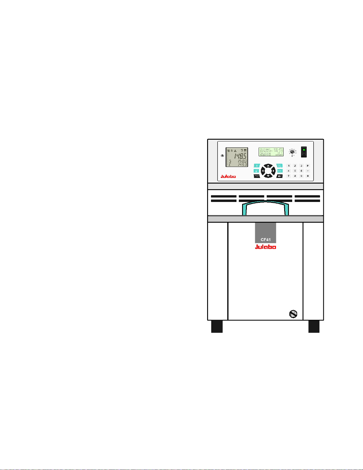
CF31
CF41
Find Quality Products Online at: [email protected]
www.GlobalTestSupply.com
Page 2

Congratulations!
You have made an excellent choice.
JULABO thanks you for the trust you have placed in us.
This operating manual has been designed to help you gain an understanding of the operation and
possible applications of our Cryo-Compact Circulators. For optimal utilization of all functions, we
recommend that you thoroughly study this manual prior to beginning operation.
Unpacking and inspecting
Unpac
Damage should be reported to the responsible carrier, railway, or postal authority, and a damage
report should be requested. These instructions must be followed fully for us to guarantee our full
support of your claim for protecting against loss from concealed damage. The form required for filing
such a claim will be provided by the carrier.
Find Quality Products Online at: [email protected]
k the Cryo-Compact Circulat or and accessories and inspect them for possible transport damage.
Important: keep original operating manual for future use
2
www.GlobalTestSupply.com
Page 3

TABLE OF CONTENTS
Cryo-Compact Circulators
1. Int
2. Operator responsibility – Safety instructions .......................................................................... 6
3. Safety notes for the user ...................................................................................................... 17
4. Operating controls and functional elements ......................................................................... 20
5. Preparations ........................................................................................................................ 24
ended use ............................................................................................
1.1. Description ........................................................................................................................ 5
2.1. Disposal ............................................................................................................................ 8
2.2. Warranty conditions ........................................................................................................... 8
2.3. EC Declaration of Conformity ............................................................................................ 9
2.4. UKCA Declaration of Conformity ..................................................................................... 11
2.5. Technical specifications ................................................................................................... 13
3.1. Explanation of safety notes .............................................................................................. 17
3.2. Explanation of other notes ............................................................................................... 17
3.3. Safety instructions ........................................................................................................... 17
.............................. 5
5.1. Installation ....................................................................................................................... 24
5.2. Temperature application to external systems................................................................... 25
5.3. Tubing ............................................................................................................................. 27
5.4. Bath fluids ....................................................................................................................... 28
6. Operating procedures .......................................................................................................... 29
6.1. Power connection ............................................................................................................ 29
6.2. Filling ............................................................................................................................... 29
6.3. Switching on / Selecting the language ............................................................................. 30
7. Manual operation ................................................................................................................. 31
7.1. Start - Stop ...................................................................................................................... 31
7.2. Control of the cooling machine ........................................................................................ 31
7.3. Setting the temperatures ................................................................................................. 32
7.4. Safety installations, warning functions ............................................................................. 33
7.4.1. Excess temperature protection ............................................................................... 33
7.4.2. Early warning system, low level protection ............................................................. 36
8. Menu functions .................................................................................................................... 37
8.1. Configuration ................................................................................................................... 38
8.2. Control............................................................................................................................. 42
Find Quality Products Online at: [email protected]
www.GlobalTestSupply.com
3
Page 4

8.3. Start of a profile ............................................................................................................... 47
8.3.1. Edit after start ......................................................................................................... 49
8.3.2. Interrupting a profile ................................................................................................ 51
8.3.3. Interruption after a power failure ............................................................................. 51
8.3.4. Termination of a profile ........................................................................................... 52
8.4. Integrated programmer .................................................................................................... 53
8.5. Analog inputs/outputs ...................................................................................................... 56
8.5.1. REG+E-PROG – temperature recorder outputs ...................................................... 58
8.5.2. REG+E-PROG - programmer input ........................................................................ 59
8.5.3. STAND-BY input .................................................................................................... 61
8.5.4. ALARM output ....................................................................................................... 62
8.6. Limits ............................................................................................................................... 63
8.7. Serial interface ................................................................................................................. 65
8.8. ATC Absolute Temperature Calibration, 3-point calibration .............................................. 66
8.9. Setting the pump pressure ............................................................................................... 69
9. Troubleshooting guide / Error messages .............................................................................. 70
10. Electrical connections ........................................................................................................... 73
11. Remote control ..................................................................................................................... 75
11.1. Setup for remote control .................................................................................................. 75
11.2. Communication with a PC or a superordinated data system ............................................ 75
11.3. List of commands ............................................................................................................. 76
11.4. Status messages ............................................................................................................. 79
11.5. Error messages ............................................................................................................... 80
12. JULABO Service – Online remote diagnosis ........................................................................ 81
13. Installation of electronic module ........................................................................................... 82
13.1. Draining ........................................................................................................................... 82
14. Cleaning / repairing the unit .................................................................................................. 83
Find Quality Products Online at: [email protected]
4
www.GlobalTestSupply.com
Page 5
Cryo-Compact Circulators
JULABO circulators ar e not suitable for direct temperature control of foods, semi-luxury
Pt100
ICC
TCF
ATC
3
RS232
RS485
PUMP
SMART
1. Intended use
JULABO Cryo-Compact Circulators have been designed for temperature application to specific fluids in
a bath tank. The units feature pump connections for temperature control of external systems (loop
circuit).
foods and tobacco, or pharmaceutical and medical products. Direct temperature control
means unprotected contact of the object with the bath medium (bath fluid).
1.1. Description
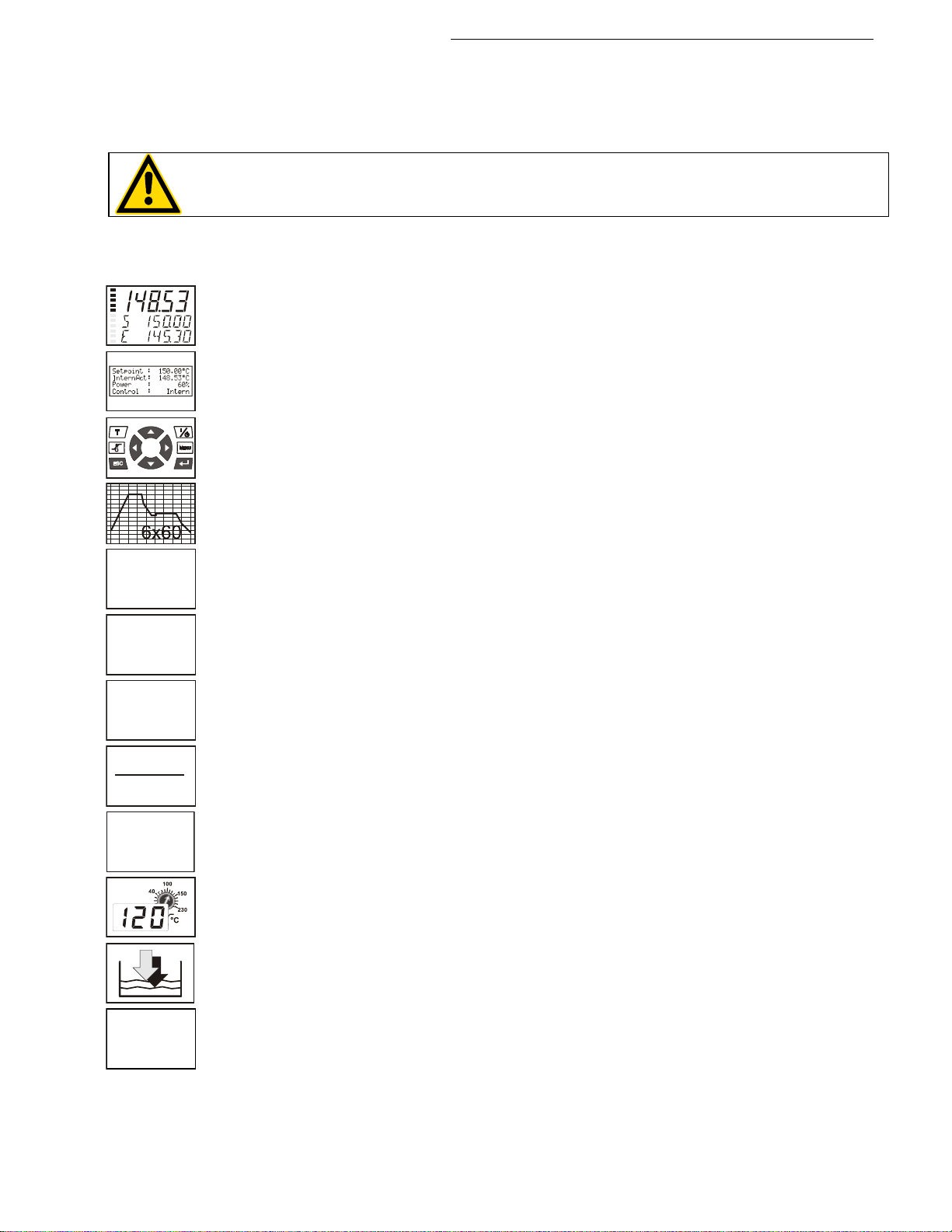
The Cryo-Compact circulators are operated via the splash-proof keypad. The
implemented microprocessor technology allows to set and to store different values
that can be indicated on the VFD COMFORT-DISPLAY and LCD DIALOGDISPLAY. Three menu keys facilitate adjusting setpoints, warning and safety
functions and menu functions.
The integrated programmer allows storing and running temperature and time-
dependent processes.
The control electronics including “ICC - Intelligent Cascade Control“ automatically
adapts the heat supplied to the thermal requirements of the bath.
The TCF - Temperature Control Features allow the user to have access to all
important temperature control parameters. This means: Full control on the control
mode and the chance to manually adjust or adapt control to the specific application.
Absolute Temperature Calibration (ATC3). With the 3-point calibration an offset is
adjusted at three temperatures to ensure an accurate temperature pattern at the
selected spot in the bath over the full temperature range.
Electrical connections:
The serial interface, switchable from RS232 to RS485, allows modern process
technology without additional interface.
Connection for Pt100 external sensor for external temperature measurement and
control.
Alarm output for external alarm message or control of JULABO refrigerating baths
or solenoid valve (cooling water).
The electronic module (option) provides 3 further analog connections (alarm input,
standby input, recorder output, programmer input).
The excess temperature protection conforming to IEC 61010-2-010 is a safety
installation independent from the control circuit. This protection can be indicated
and set on the LCD DIALOG-DISPLAY.
The early warning system for low level signals that bath fluid needs to be refilled
before the low level protection conforming to IEC 61010-2-010 causes a complete
shut-down of the main functional elements.
Intelligent pump system: The pump capacity (electronically adjustable via the motor
speed) enables to adapt to varying conditions for internal and external temperature
applications..
Find Quality Products Online at: [email protected]
www.GlobalTestSupply.com
5
Page 6

Operator responsibility – Safety instructions
2. Operator responsibility – Safety instructions
The products of JULABO ensure safe operation when installed, operated, and maintained according to
common safety regulations. This section explains the potential dangers that may arise when operating
the circulator and also specifies the most important safety precautions to preclude these dangers as far
as possible.
The operator is responsible for the qualification of the personnel operating the units.
The personnel operating the units should be regularly instructed about the dangers involved with
their job activities as well as measures to avert these dangers.
Make sure all persons tasked with operating, installing, and maintaining the unit have read and
understand the safety information and operating instructions.
When using hazardous materials or materials that could become hazardous, the circulator may be
operated only by persons who are absolutely familiar with these materials and the circulator. These
persons must be fully aware of possible risks.
Safety instruction s for the operator:
Av
Make sure the product is checked for proper condition regularly (depending on the conditions of
Make sure that the mains power supply has low impedance to avoid any negative effects on the
This unit is designed for operation in a controlled electromagnetic environment. This means that
Magnetic radiation may affect other devices with components sensitive to magnetic fields (e.g.,
Permissible ambient temperature: max. 40 °C, min. 5 °C.
Permissible relative humidity: 50% (40 °C).
Do not store the unit in an aggressive atmosphere. Protect the unit from contamination.
Do not expose the unit to sunlight.
Appropriate operati on
Onl
Persons who operate the circulator must be trained in the particular tasks by qualified personnel. The
summarized user guidance (short manual) and the specification table with information on individual
parameters are sufficient for this.
oid strikes to the housing, vibrations, damage to the operating-element panel (keypad, display),
and contamination.
use). Regularly check (at least every 2 years) the proper condition of the mandatory, warning,
prohibition and safety labels.
instruments being operated on the same mains.
transmitting devices (e.g., cellular phones) should not be used in the immediate vicinity.
monitors). We recommend maintaining a minimum distance of 1 m.
y qualified personnel is authorized to configure, install, maintain, or repair the circulator.
Find Quality Products Online at: [email protected]
6
www.GlobalTestSupply.com
Page 7
Cryo-Compact Circulators
or
Use
The bath can be filled with flammable materials. Fire hazard!
There might be chemical dangers depending on the bath medium used.
Observe all warnings for the used materials (bath fluids) and the respective instructions (safety data
sheets). Insufficient ventilation may result in the formation of explosive mixtures. Only use the unit in
well ventilated areas. Only use recommended materials (bath fluids). Only use non-acid and non
corroding materials.
When using hazardous materials or materials that could become hazardous, the operator must affix
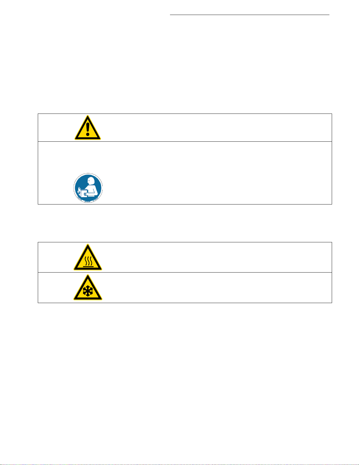
the enclosed safety labels (1 + 2) to the front of the unit so they are highly visible:
1
Danger area. Attention! Observe instructions.
(operating manual, safety data sheet)
2a
2b
Carefully read the user information prior to beginning operation.
Scope: EU
Carefully read the user information prior to beginning operation.
Scope: USA, NAFTA
Particular care and attention is necessary because of the wide operating range. There are thermal
dangers: Burn, scald, hot steam, hot parts and surfaces that can be touched.
Hot surface warning.
(The label is put on by JULABO)
Low temperature warning.
(The label is put on by JULABO)
Observe the instructions in the manuals for instruments of a different make that you connect to the
circulator, particularly the corresponding safety instructions. Also observe the pin assignment of plugs
and technical specifications of the products.
Find Quality Products Online at: [email protected]
www.GlobalTestSupply.com
7
Page 8

Operator responsibility – Safety instructions
Valid in EU countries
waste is not permitted!
2.1. Disposal
The product may be used with oil as bath fluid. These oils fully or partially consist of mineral oil or
synthetic oil. For disposal, follow the instructions in the material safety data sheets.
This unit contains refrigerants, which at this time are not considered harmful to the ozone layer.
However, over the long operating period of the unit, disposal rules may change. Therefore, only
qualified personnel should handle the disposal.
See the current official journal of the E uropean Union – WEEE directive.
Directive of the European Parliament and of the Council on waste electrical and
electronic equipment (WEEE).
This directive requires electrical and electronic equipment marked with a crossedout trash can to be disposed of separately in an environmentally friendly manner.
Contact an authorized waste management company in your country.
Dis
posal with household waste (unsorted waste) or similar collections of municipal
2.2. Warranty conditions
JULABO GmbH warrants its products against defects in material or in workmanship, when used under
appropriate conditions and in accordance with appropriate operating instructions
for a period of ONE YEAR.
Extension of the warranty period – free of charge
With the ‘1PLUS warranty’ the user receives a free of charge extension to the warranty of up to 24
months, limited to a maximum of 10 000 working hours.
To apply for this extended warranty the user must register the unit within four weeks after
commissioning on , indicating the serial no. The extended warranty will apply from
the date of JULABO GmbH’s original invoice.
JULABO GmbH reserves the right to decide the validity of any warranty claim. In case of faults arising
either due to faulty materials or workmanship, parts will be repaired or replaced free of charge, or a
new replacement unit will be supplied.
Any other compensation claims are excluded from this guarantee.
Find Quality Products Online at: [email protected]
8
www.GlobalTestSupply.com
Page 9

2.3. EC Declaration of Conformity
Cryo-Compact Circulators
Find Quality Products Online at: [email protected]
www.GlobalTestSupply.com
9
Page 10

Operator responsibility – Safety instructions
Find Quality Products Online at: [email protected]
10
www.GlobalTestSupply.com
Page 11
Cryo-Compact Circulators
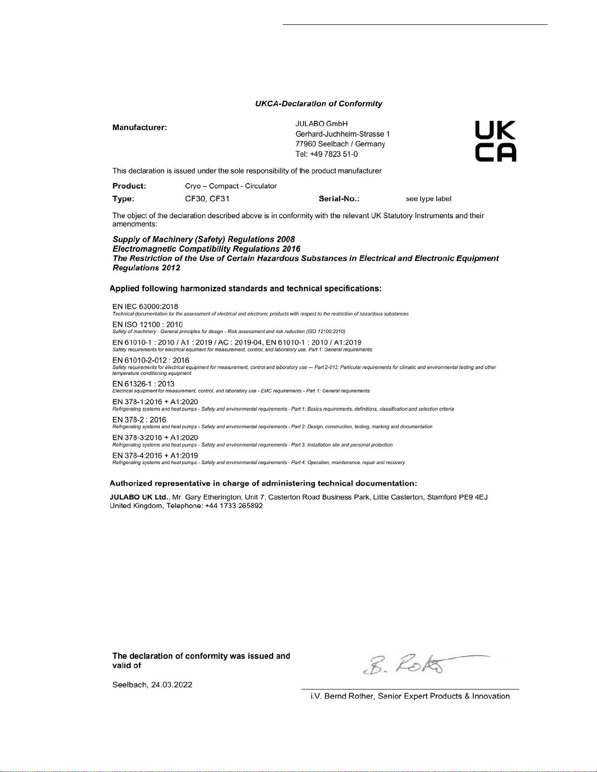
2.4. UKCA Declaration of Conformity
UK Office: JULABO UK Ltd., Unit 7, Casterton Road Business Park, Old Great North Road, Little
Casterton, Stamford, PE9 4EJ, United Kingdom, Tel.: +44 1733 265892
Find Quality Products Online at: [email protected]
www.GlobalTestSupply.com
11
Page 12
Operator responsibility – Safety instructions
Find Quality Products Online at: [email protected]
12
www.GlobalTestSupply.com
Page 13

Cryo-Compact Circulators
CF31
Working temperature range
°C
-30 ... +200
Temperature stability
°C
±0.02
Temperature selection
digital
via keypad
indication on LCD DIALOG-DISPLAY (°C/°F)
remote control via personal
computer
indication on monitor
Temperature indication:
VFD COMFORT-DISPLAY
Resolution
°C
0.01
Pump pressure stage
indication on VFD COMFORT-DISPLAY
Temperature control
ICC - Intelligent Cascade Control
Working temperature sensor
Pt 100
Safety temperature sensor
Pt 100
Absolute Temperature Calibration
at internal control
°C
±3
at external control
°C
±10
Heater wattage (at 230 V)
kW
2,0
Heater wattage (at 115 V)
kW
1,0
Cooling capacity
°C
20 0 -20
Medium ethanol
kW
0.32 0.25 0.15
Cooling compressor
1-stage
Refrigerant
R134a
Cooling machine
Air-cooled
Electronically adj. pump capacity
1 ... 4 stages
Flow rate min ... max. at 0 bar
l/min
22 ... 26
Pressure max. at 0 liter
bar
0,7
Suction max at 0 liter
bar
0,4
Bath opening (WxL)
cm
16x3
Bath depth
cm
14
Filling volume
liters
2.0 ... 3.0
Overall dimensions (WxDxH)
cm
24x46x40
Weight
kg
35
Mains power connection 230 V/50 Hz
V/Hz
207-253 / 50
Current draw (at 230 V)
A
11
Mains power connection 230 V/60 Hz
V/Hz
207-253 / 60
Current draw (at 230 V)
A
12
Mains power connection 115 V/60 Hz
V/Hz
103-127 / 60
Current draw (at 115 V)
A
14
2.5. Technical specifications
Performance specifications measured in accordance with DIN12876. Cooling capacities up to
20°C measured with ethanol; over 20°C with thermal oil unless specified otherwise.
Performance specifications apply at an ambient temperature of 20°C. Performance values
may differ with other bath fluids.
All measurements have been carried out at: rated voltage and frequency ambient temperature: 20 °C.
Find Quality Products Online at: [email protected]
www.GlobalTestSupply.com
13
Page 14

Operator responsibility – Safety instructions
CF41
Working temperature range
°C
-40 ... +200
Temperature stability
°C
±0.02
Temperature selection
digital
via keypad
indication on LCD DIALOG-DISPLAY (°C/°F)
remote control via personal
computer
indication on monitor
Temperature indication:
VFD COMFORT-DISPLAY
Resolution
°C
0.01
Pump pressure stage
indication on VFD COMFORT-DISPLAY
Temperature control
ICC - Intelligent Cascade Control
Working temperature sensor
Pt 100
Safety temperature sensor
Pt 100
Absolute Temperature Calibration
at internal control
°C
±3
at external control
°C
±10
Heater wattage (at 230 V)
kW
2,0
Heater wattage (at 115 V)
kW
1,0
Cooling capacity
°C
20 0 -20 -30
kW
0.47 0.4 0.28 0.12
Cooling compressor
1-stage
Refrigerant
R452A* R449A**
Cooling machine
Air-cooled
Electronically adj. pump capacity
1 ... 4
Flow rate min ... max. at 0 bar
l/min
22 ... 26
Pressure max. at 0 liter
bar
0,7
Suction max at 0 liter
bar
0,4
Bath opening (WxL)
cm
19x3
Bath depth
cm
19
Filling volume
Liter
4.0 ... 5.5
Overall dimensions (WxDxH)
cm
28x46x46
Weight
kg
42
Mains power connection 230 V/50 Hz
V/Hz
207-253 / 50
Current draw (at 230 V)
A
13
Mains power connection 230 V/60 Hz
V/Hz
207-253 / 60
Current draw (at 230 V)
A
13
Mains power connection 115 V/60 Hz
V/Hz
103-127 / 60
Current draw (at 115 V)
A
16
* at 230 V/50 Hz,
** at 230 V/60 Hz, 115 V/60 Hz
measurements have been carried out at: rated voltage and frequency am bient temperature: 20 °C
All
Technical changes without prior notification reserved.
Find Quality Products Online at: [email protected]
14
www.GlobalTestSupply.com
Page 15
Electrical connections:
Caution:
Computer interface RS232 / RS485
External sensor Pt100
Cryo-Compact Circulators
Optional: (O
Programmer input -100 °C to 400 °C = 0 - 10 V or 0 - 20 mA or 4 - 20 mA
Input for the signal of a flow meter or external manipulated variable
Temperature recorder outputs 0 - 10 V (0 V = -100 °C, 10 V = 400 °C)
0 - 20 mA (0 mA = -100 °C, 20 mA = 400 °C)
4 - 20 mA (4 mA = -100 °C, 20 mA = 400 °C)
Standby input for external emergency switch-off
Alarm output for external alarm signal
Warning functions and safety installations
Excess temperature protection adjustable from 0 °C ... 220 °C
Low liquid level protection float switch
Early warning system for low level float switch
Classification according to DIN 12876-1 class III
Alarm message optical + audible (permanent)
Warning message optical + audible (in intervals)
Overload protection for compressor and pump motor
High temperature warning function optical + audible (in intervals)
Low temperature warning function optical + audible (in intervals)
Supervision of working sensor plausibility control
Reciprocal sensor monitoring between
working and safety sensors difference >35 K
rder No. 8900100 Electronic module with analog connections)
Environmental conditions according to IEC 61 010-1:
Use indoors only.
Altitude up to 2000 m - normal zero.
Ambient temperature: see Technical specifications
Humidity:
Max. relative humidity 80% for temperatures up to +31 °C,
linear decrease down to 50% relative humidity at a temperature of +40 °C
Protection class according to IEC 60 529 IP21
The unit corresponds to Class I
Overvoltage category II
Pollution degree 2
The unit is not suitable for use in explosive atmosphere
Find Quality Products Online at: [email protected]
www.GlobalTestSupply.com
15
Page 16

Operator responsibility – Safety instructions
Note!
environments.
EMC requirements according to EN 61326-1:
The device is an ISM device of group 1 per CISPR 11 (uses HF for internal purposes) and is
classified in class A (industrial and commercial sector).
• Devices of class A are intended for the use in an industrial
electromagnetic envi r o nme nt.
• When operating in other electromagnetic environments, their
electromagnetic compatibility may be impacted.
• This device is not intended for the use in living areas and cannot
guarantee adequate protection of the radio reception in such
Information about the used refrigerants
The Regulation (EU) No. 517/2014 on fluorinated greenhouse gases applies to all systems which
contain fluorinated refrigerants and replaces (EC) 842/2006.
The aim of the Regulation is to protect the environ ment by reducing emissions of fluorinated greenhouse
gases.
Among other things it regulates the emission limits, use and recovery of these substances. It also
contains requirements for operators of systems which require / contain these substances to function.
Under Regulation 517/2014, the operator of a system of this nature has the following duties:
• The operator must ensure that the equipment is checked at regular intervals for leaks.
• These intervals depend on the CO
refrigerant fill volume and type of refrigerant. The CO
model plate.
• The operator undertakes to have maintenance, repair, service, recovery and recycling work
carried out by certified personnel who have been authorized by JULABO.
• All such work must be documented. The operator must keep records and archive them for at
least five years. The records must be submitted to the relevant authority on request.
Refer to the text of the Regulation for further information.
equivalent of the system. This is calculated from the
2
equivalent of your system is shown on the
2
Find Quality Products Online at: [email protected]
16
www.GlobalTestSupply.com
Page 17
3. Safety notes for the user
In addition to the safety warnings listed above, warnings are posted throughout the
Warning:
Caution:
Notice:
its surroundings can be damaged.
Note!
Draws attention to something special.
Important!
Indicates usage tips and other useful information.
Follow the safety instructions to avoid personal injury and property damage. Also, the
• Prevent water from entering the hot bath oil.
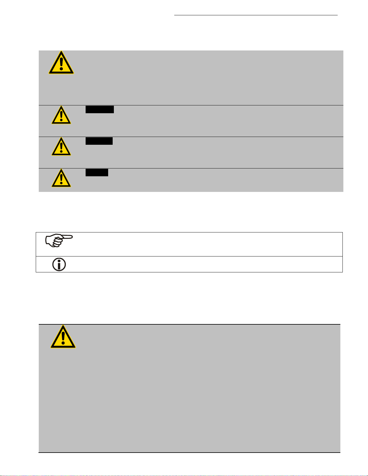
3.1. Explanation of safety notes
manual. These warnings are designated by an exclamation mark inside an equilateral
triangle. “Warning of a dangerous situation (Attention! Please follow the
documentation).”
The danger is classified using a signal word.
Read and follow these important instructions.
Describes a possibly highly dangerous situation. If these instructions are not followed,
serious injury and danger to life could result.
Describes a possibly dangerous situation. If this is not avoided, slight or minor injuries
could result. A warning of possible property damage may also be contained in the text.
Describes a possibly harmful situation. If this is not avoided, the product or anything in
Cryo-Compact Circulators
3.2. Explanation of other notes
3.3. Safety instructions
valid safety instructions for workplaces must be followed.
• Only connect the unit to a power socket with an earthing contact (PE – protective
earth)!
• The power supply plug serves as a safe disconnecting device from the line and
must always be easily accessible.
• Place the unit on an even surface on a base made of nonflammable material.
• Do not stay in the area below the unit.
• Make sure you read and understand all instructions and safety precautions listed
in this manual before installing or operating your unit.
• Set the excess temperature safety installation below the flash point of the bath
fluid.
Find Quality Products Online at: [email protected]
• Never operate the unit without bath fluid in the bath.
• Pay attention to the thermal expansion of bath oil during heating to avoid
overflowing of the fluid.
www.GlobalTestSupply.com
17
Page 18

Safety notes for the user
touching these parts.
• Do not drain the bath fluid while it is hot!
Check the temperature of the bath fluid prior to draining (e.g., by switching the
unit on for a short moment).
• Use suitable connecting tubing.
• Avoid sharp bends in the tubing and maintain a sufficient distance from
surrounding walls.
• Make sure that the tubing is securely attached.
• Regularly check the tubing for material defects (e.g., for cracks).
• Never operate damaged or leaking units.
• Always turn off the unit and disconnect the mains cable from the power source
before performing any service or maintenance procedures, or before moving the
unit.
• Always turn off the unit and disconnect the mains cable from the power source
before cleaning the unit.
• Always empty the bath before moving the unit.
• Transport the unit with care.
• Sudden jolts or drops may cause damage in the interior of the unit.
• Observe all warning labels.
• Never remove warning labels.
• Never operate units with damaged mains power cables.
• Repairs are to be carried out only by qualified service personnel.
• Some parts of the bath tank and the pump connections may become extremely
hot during continuous operation. Therefore, exercise particular caution when
touching these parts.
• Some parts of the bath tank and the pump connections may become extremely
cold during continuous operation. Therefore, exercise particular caution when
Find Quality Products Online at: [email protected]
18
www.GlobalTestSupply.com
Page 19

Cryo-Compact Circulators
The following questions should help to recognize possible dangers and to reduce the
determine the method of decontamination.
for example.
risks to a minimum.
• Are all tubes and electrical cables connected and layed?
Note:
sharp edges, hot surfaces in operation, moving machine parts, etc.
• Do dangerous vapors or gases develop during heating?
Must the work be done in a fume hood?
• What to do when a dangerous substance was spilled on or in the unit?
Before starting to work, obtain information concerning the substance and
Notice:
Check the safety installations at least twice a year!
• Excess temperature protection according to IEC 61010-2-010
With a screwdriver, turn back the adjustable excess temperature protection until
the shutdown point (actual temperature).
• Low level protection according to IEC 61010-2-010
To check the function of the float, it can be manually lowered with a screwdriver,
Find Quality Products Online at: [email protected]
www.GlobalTestSupply.com
19
Page 20
Operating controls and functional elements
8b
ext
Pt100
SERIAL
ALAR
REGE-STAND-
T16A
T16A
910111213
14
151617
T16A
T16A
8b1516
17
14
ext
Pt100
SERIAL
ALAR
REGE-STAND-
910111213
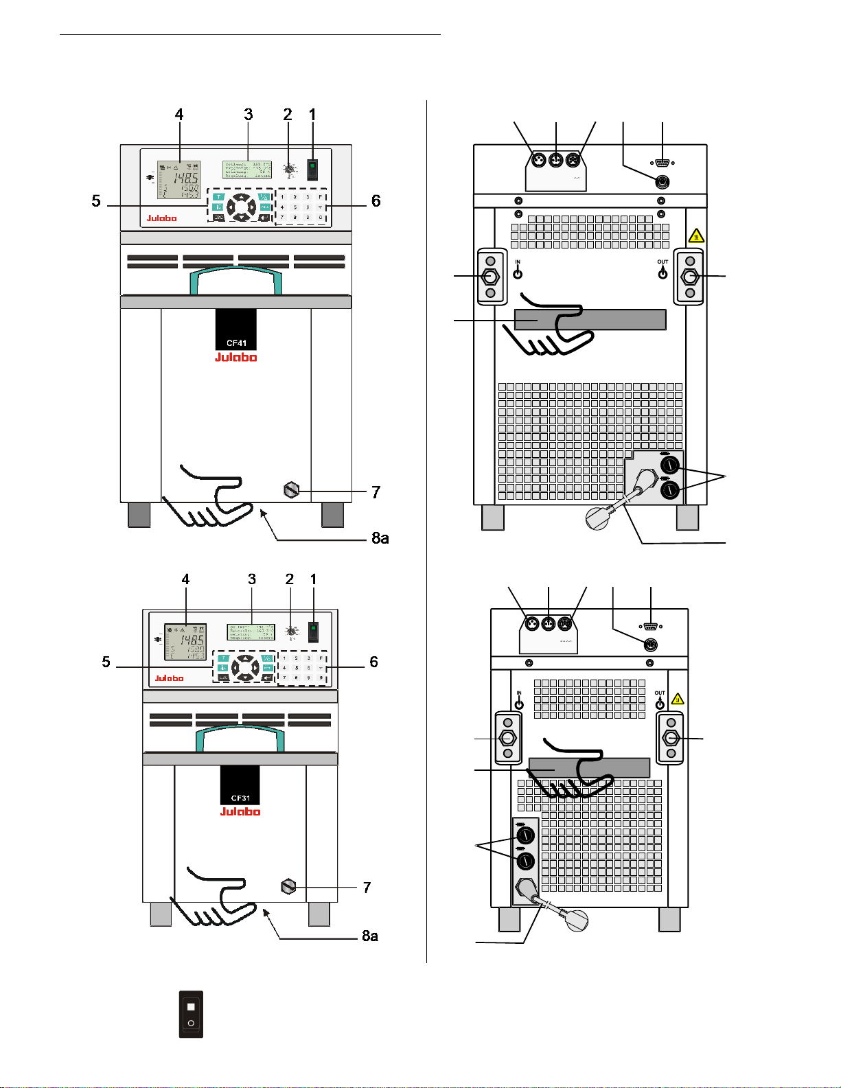
1 Mains power switch, illuminated
4. Operating controls and functional elements
Front view CF41 / CF31 Rear view CF41/ CF31
Find Quality Products Online at: [email protected]
20
www.GlobalTestSupply.com
Page 21
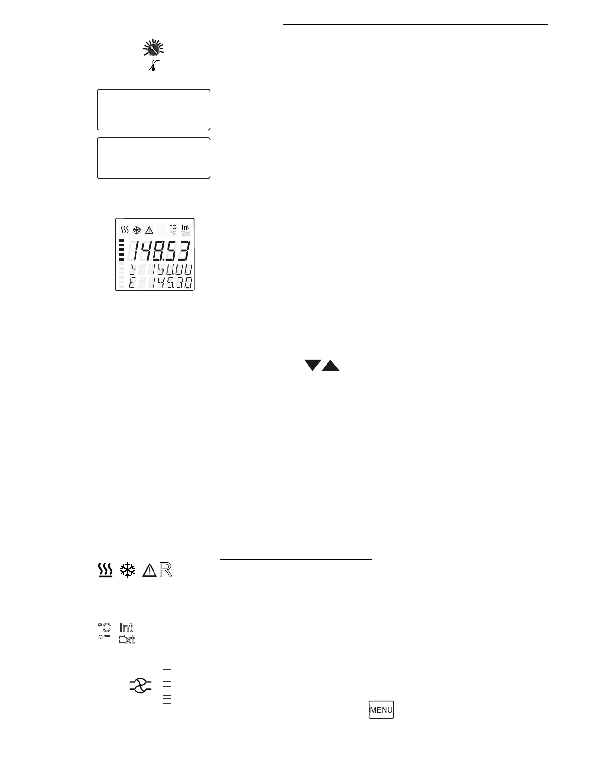
Cryo-Compact Circulators
2
°C
140
100
180
220060
20
Adjustable excess temperature protection according to
3
Setpoint1: 150.00°C
IntAct : 148.53°C
Power : 80 %
Control : intern
RS232 : 150.00°C
ExtAct : 145.30°C
Power : 80 %
Control : extern
LCD DIALOG-DISPLAY
4
4.1
4.2
IEC 61010-2-010
Line 1: Setpoint and origin of setpoint programming
(Key / RS232 or RS485 / ext. Pt100 / EProg)
Line 2: Actual value - internal or external,
identical to line 1 of the VFD-COMFORT-DISPLAY
Line 3: Heating capacity in %.
Line 4: Control type: internal / external
VFD-COMFORT-DISPLAY
Header: Control indicators see sections 4.1 and 4.2
Line 1: Actual value internal or external
The display is depending on the selected control mode in the
menu > Control < (internal or external).
Line 2: Working temp. setpoint, constantly S xxx.xx
Line 3: Actual value (E = external or I = internal)
Alternating with the display in line 1
Use the keys to indicate further values in line 3.
However, the functions of these keys are different with the
programmer started.
PI Capacity in % - with manipulated variable set to >control<*
PS Capacity in % - with manipulated variable set to >serial<* or
>eprog<*
H Heater capacity in Watts
U Mains voltage Volts
F Flow rate in liters/minute
(providing EPROG input set to >Flowrate<)
*see >Configuration> page 38
Control indicators in the header:
Heating / Cooling / Alarm /
Remote control
Control indicators in the header:
Temperature indication Internal or External actual value
Temperature indication in °C or °F (see page 41)
Display for the adjusted pump pressure stage in the -OFF- mode.
4.3
Find Quality Products Online at: [email protected]
Display for the effective pump pressure stage (rotation speed) after
start.
Four stages, adjustable via the button, in the menu >PUMP<.
www.GlobalTestSupply.com
21
Page 22
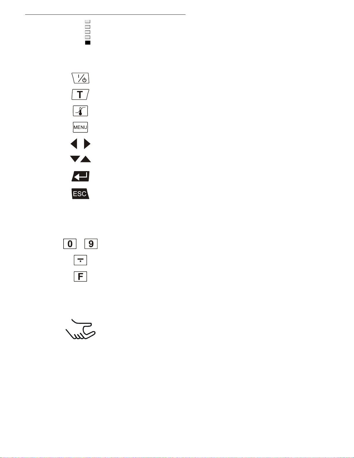
Operating controls and functional elements
5
Key for selecting the working temperature - Setpoint 1, 2, 3
Key for selecting the warning and safety values
Cursor keys (left or right)
Edit keys (increase or decrease)
6
Numeral keypad: numerals 0 to 9
minus / decimal point
F key: Shows the help text in the
7
Drain port
8a
Handle: front
4.4
Keypad 1
Segment at bottom blinks: Standstill of compressor
(compressor protection device, page 31)
Start / stop key
MENU key - for selecting the menu functions
Enter key 1) Store value / parameter
2) Next lower menu level
Escape key 1. Cancel entries
2. Return to a higher menu level
Keypad 2
..
8b
LCD DIALOG-DISPLAY when alarm messages appear.
Handle: rear
Find Quality Products Online at: [email protected]
22
www.GlobalTestSupply.com
Page 23
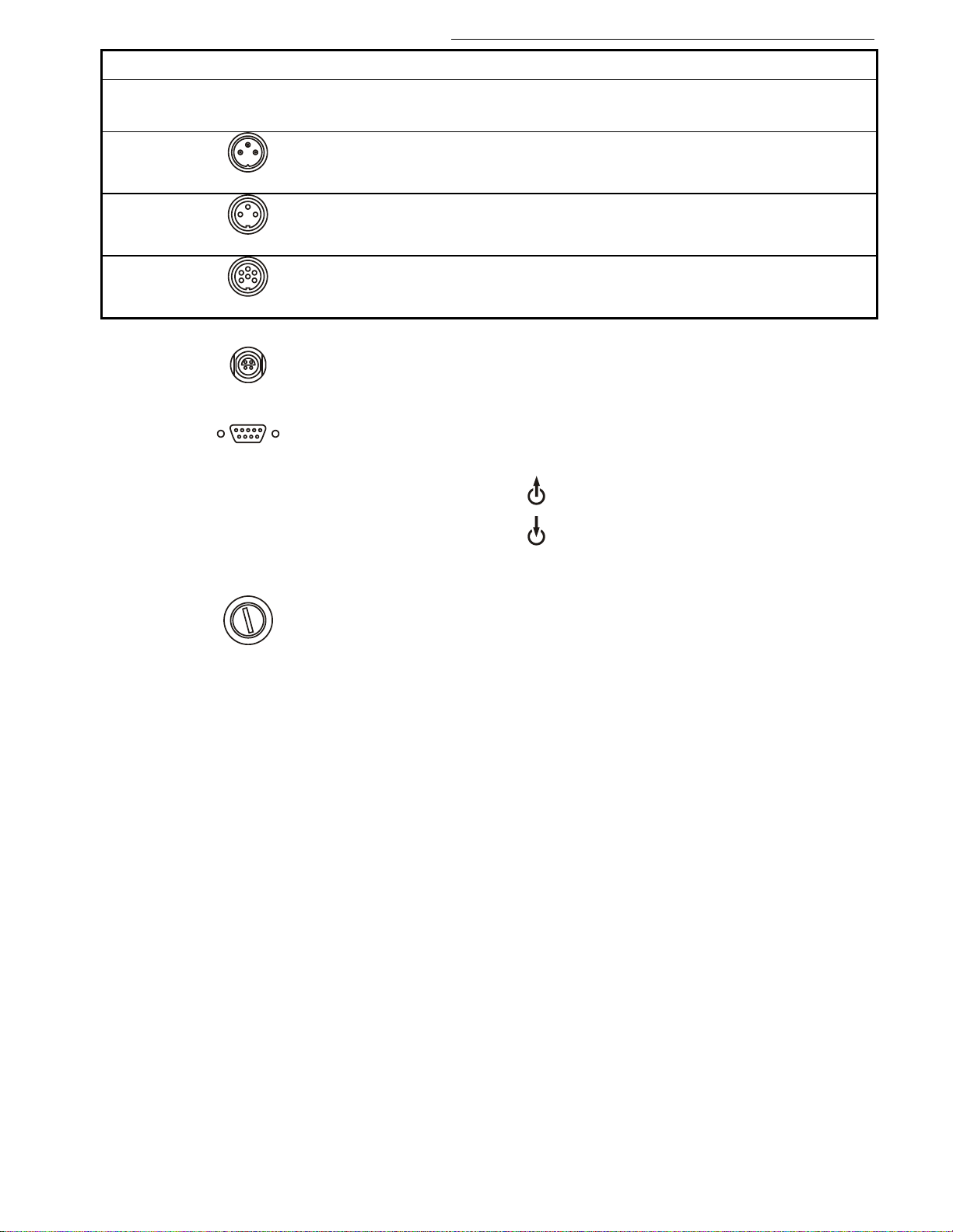
Option: Electronic module Or der No. 8 900 100
The Cryo-Compact Circulator automatically recognizes the
9
ALARM
Alarm output (for external alarm signal)
10
STAND-BY
Standby input (for external emergency switch-off)
11
REG+E-PROG
Programmer input and temperature recorder output
12
Socket for external measurement and control sensor
13
Interface RS232 / RS485: remote control via personal computer
14
15
16
Mains fuses: T16A
17
Mains power cable with plug
connected electronic module.
Cryo-Compact Circulators
ext Pt100
SERIAL
or external setpoint programming
Pump connection OUT - pressure pump, M16x1
Pump connection IN – suction pump, M16x1 (return)
T20A (CF41 115 V / 60 Hz)
Find Quality Products Online at: [email protected]
www.GlobalTestSupply.com
23
Page 24

Preparations
maximum cooling performance of the compressor.
5. Preparations
5.1. Installation
• Place the unit on an even surface on a base made of
nonflammable material.
• Cooling machine, pump motor and electronics produce intrinsic
heat that is dissipated via the venting openings.! Never cover
these openings!
• Be sure that the flow of ventilation can exit under the
instrument.
• Keep at least 20 cm of open space on the side and rear of the
unit.
• Do not set up the unit in the immediate vicinity of heat sources
and do not expose to sun light.
• Before operating the unit after transport, wait about one hour
after setting it up. This will allow any oil that has accumulated
laterally during transport to flow back down thus ensuring
• The place of installation should be large enough and provide
sufficient air ventilation to ensure the room does not warm up
excessively because of the heat the instrument rejects to the
environment.
(Max. permissible ambient temperature: 35 °C).
For a fault (leakage) in the refrigeration system, the standard
EN 378 prescribes a certain room space to be available for
each kg of refrigerant.
The refrigerant quantity is specified on the type plate.
3
> For 0.423 kg of refrigerant R452A, 1 m
> For 0.25 kg of refrigerant R134a, 1 m
> For 0.357 kg of refrigerant R449A, 1 m
of space is required.
3
of space is required.
3
of space is required.
Model CF41 with 0.17 kg filling quantity of refrigerant R452A =
3
0,4 m
volume
Model CF41 with 0.15 kg filling quantity of refrigerant R449A =
3
0,42 m
Model CF31 with 0.15 kg filling quantity of refrigerant R134a =
0.6 m
volume
3
volume
Find Quality Products Online at: [email protected]
24
www.GlobalTestSupply.com
Page 25
5.2. Temperature application to external systems
The Cryo-Compact Circulator is used for temperature application to external systems
(loop circuit)
different heights, overflowing must be prevented after the power has been turned off.
8 970 457 Shut-off valve (suitable up to +200 °C)
Tubing see page 27
Caution: Securely attach all tubing to prevent slipping.
Notice: Flood hazard!
If the liquid levels in the Cryo-Compact Circulator bath and the external system are at
Return flow safety device
For this reason, shut-off valves can be integrated in the loop circuit.
Order No. Desc
8 970 456 Shut-off valve (suitable up to +90 °C)
ription
Cryo-Compact Circulators
Temperature application to external, closed systems
• Unscrew the M16x1 collar nuts on the pump
connectors with a 19 mm (3/4“) wrench and
remove the sealing disks. Using the collar
nuts, screw on the tubing connection fittings
(for tubing 8 mm or 12 mm in diameter)
delivered with the unit and tighten firmly.
(Pressure pump: 14, suction pump: 15)
• Push on the tubings, and secure with tube
clamps.
• Attach the tubing to the connectors of the
external closed system, e.g., an instrument
with a pressure-resistant temperature jacket
or a temperature coil, and fasten with tube
clamps to prevent slipping.
Find Quality Products Online at: [email protected]
www.GlobalTestSupply.com
25
Page 26
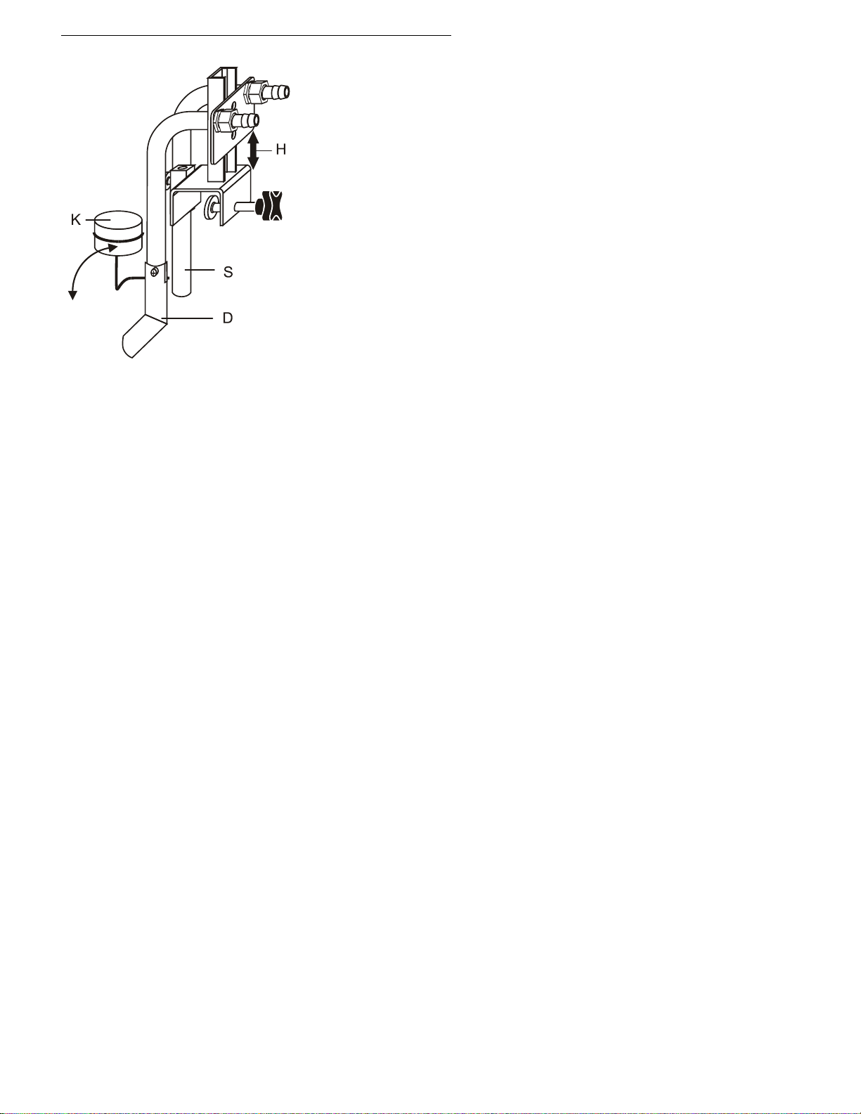
Preparations
H = Height adjustment
Temperature application to external, open systems
S = Suction pump connection
D = Pressure pump connection
K = Float
The Cryo-Compact Circulator is equipped with both a pressure and
suction pump for external temperature application in open systems.
Differing flow rates of the pressure and suction pumps should be
compensated. To maintain a constant liquid level, the JULABO
„D+S“ Level Adapter is recommended for the external bath tank.
The flow rate of the pressure pump will be then regulated by a builtin float device. The liquid level may be changed by a height
adjustment on the „D+S“ Level Adapter.
Accessory: „D+S“ Level Adapter Order No. 8 970 410
Important:
The liquid level should be equal in the internal and external
baths (absolute height).
If you take out samples (for example Erlenmeyer flasks) from
the external bath, turn the Cryo-Compact Circulator off with the
Start/Stop key.
Find Quality Products Online at: [email protected]
26
www.GlobalTestSupply.com
Page 27

5.3. Tubing
Warning: Tubing:
• Preventive maintenance: replace the tubing from time to time.
Order No.
Suitable for
8930008
1 m CR®-tubing 8 mm inner dia. (-20 ... +120°C)
CF31, CF41
8930012
1 m CR®-tubing 12 mm inner dia. (-20 ... +120°C)
CF31, CF41
8930108
1 m Viton® tubing 8 mm inner dia (-35 °C bis 200 °C)
CF31, CF41
8930112
1 m Viton® tubing 12 mm inner dia (-35 °C bis 200 °C)
CF31, CF41
8930410
1 m Insulation, 14 mm inner dia..
CR®-tubing 8 mm inner dia
8930412
1 m Insulation, 18 mm inner dia.
Viton® tubing 12 mm inner dia.
8970480
2 Tube clamps, size 1
CR®-tubing 8 mm inner dia
8970481
2 Tube clamps, size 2
Viton® tubing 12 mm inner dia.
8 930 209 0.5 m
8 930 214 3.0 m
-100 °C ... +350 °C
8 930 220 0.5 m
8 930 223 3.0 m
-50 °C to +200 °C
At high working temperatures, the tubing used for temperature control and for the
cooling water supply represents a danger source.
Recommended tubing:
A damaged tubing line may allow a large amount of hot bath fluid to be pumped out
within a short time.
This may result in:
• Burning of skin
• Breathing difficulties due to hot atmosphere
Safety instructions
• Use suitable connecting tubing.
• Make sure that the tubing is securely attached.
• Avoid sharp bends in the tubing and maintain a sufficient distance from
surrounding walls.
• Regularly check the tubing for material defects (e.g., for cracks), at least once a
year.
Cryo-Compact Circulators
Tubing insulation
Tube clamps
Metal tubing, flexible, triple insulated
8 930 210 1.0 m
8 930 211 1.5 m
Metal tubing, flexible, insulated
8 930 221 1.0 m
8 930 222 1.5 m
2 fittings M16x1 female
2 fittings M16x1 female
Find Quality Products Online at: [email protected]
www.GlobalTestSupply.com
27
Page 28
Preparations
Caution:
cause corrosion in the bath, even on stainless steel.
Bath fluid
Temperature range
soft/decalcified water
5 °C to 80 °C
Contact: see page 6
No liability for use of other bath fluids!
5.4. Bath fluids
Carefully read the material safety data sheet of the bath fluid used, particularly with
regard to the fire point!
If a bath fluid with a fire point of ≤ 65 °C is used, only supervised operation is
possible.
Water:
The quality of water depends on local conditions.
• Due to the high concentration of lime, hard water is not suitable for temperature
control because it leads to scale in the bath
• Ferrous water can cause corrosion, even on stainless steel.
• Chlorinated water can cause pitting corrosion.
• Distilled water and deionized water are unsuitable. Their special properties
Recommended bath fluids:
Caution:
Fire or other dangers when using bath fluids that are not recommended:
Please contact JULABO before using other than recommended bath liquids.
JULABO assumes no liability for damage caused by the selection of an unsuitable
bath fluid.
Unsuitable bath fluids are fluids which, e.g.,
• are highly viscous
(much higher than 70 mm2 x s-1 at the respective working temperature)
• have a low viscosity and have creep characteristics
• have corrosive characteristics or
• tend to crack.
ATTENTION: The maximum permissible viscosity is 70 mm2/s
See website for list of recommended bath fluids.
Find Quality Products Online at: [email protected]
28
www.GlobalTestSupply.com
Page 29
6. Operating procedures
Caution:
• We disclaim all liability for damage caused by incorrect line voltages!
specified on the type plate.
A volume change of 12 % per 100 °C temperature variation is to be considered.
6.1. Power connection
• Only connect the unit to a power socket with an earthing contact (PE – protective
6.2. Filling
earth)!
• The power supply plug serves as a safe disconnecting device from the line and
must always be easily accessible.
• Never operate the unit with a damaged mains power cable.
• Regularly check the mains power cables for damage.
Make sure that the line voltage and frequency match the supply voltage
Notice:
Pay attention to the thermal expansion of bath oil during heating to avoid overflowing of
the liquid.
Guideline:
Cryo-Compact Circulators
Take care that no liquid enters the interior of the Cryo-Compact
Circulator .
Connect the tubing from the exter nal system to the pump
connectors and check for leaks
Check to make sure that the drain tap (7) is closed.
Recommendation:
For filling, use for example an measuring jug with nuzzle.
Recommended maximum filling level with water as bath fluid:
30 mm below the tank rim
Recommended maximum filling level with bath oils:
40 mm below the tank rim
• Turn the mains switch (1) on
(Switching on - see page 30)
• Switch on unit by pressing the start/stop key .
Find Quality Products Online at: [email protected]
• Tempering fluid is pumped into the externally connected system.
Refill fluid up to recommended filling level.
• The Cryo-Compact Circulator is ready for operation.
www.GlobalTestSupply.com
29
Page 30
Operating procedures
cooling coil is not completely covered with bath fluid, refill it.
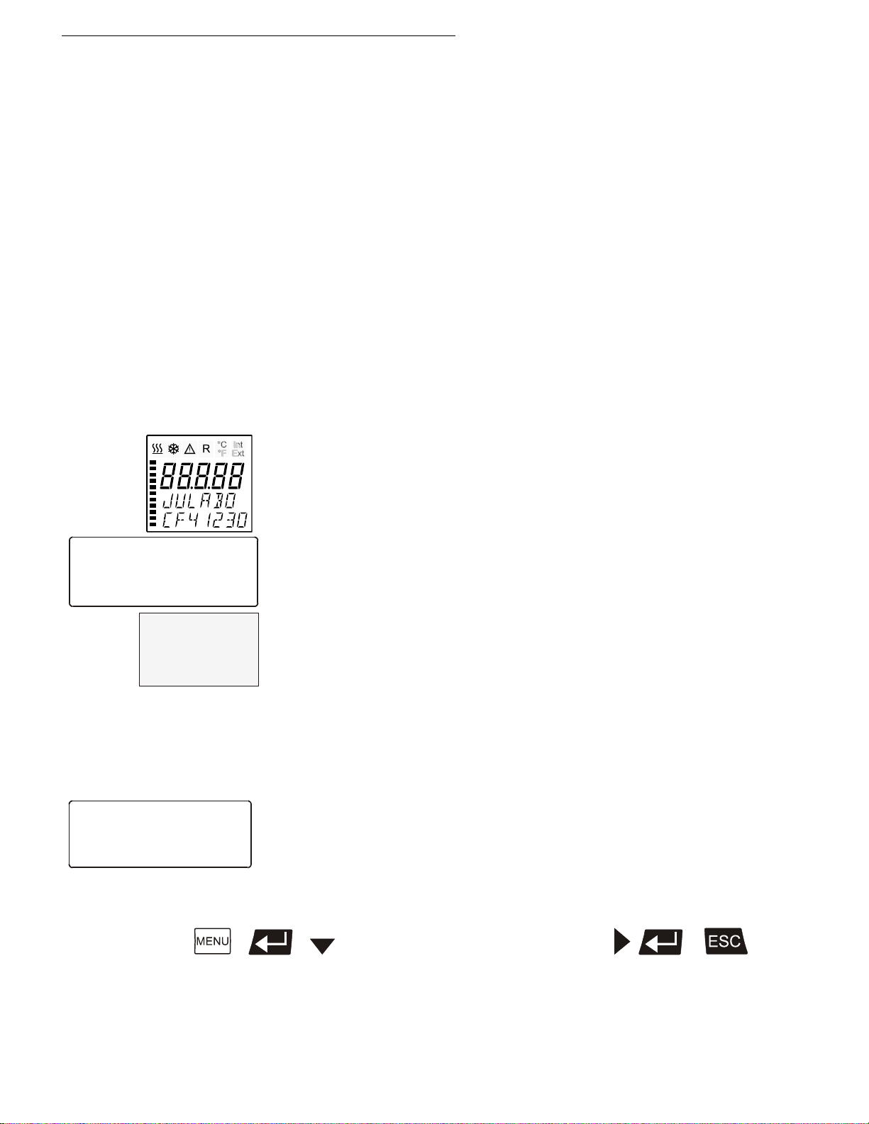
**** JULABO ****
*** HighTech ***
** Compact **
* Version 1.02-41 *
-OFF-
S 150.00
I 24.60
Configuration
Off-Mode : pump off
>Language : english
Reset : no
Press the respective keys in the following order:
Important:
When using a bath fluid, the change in volume in case of change in
temperature has to be respected. Fill in a little amount of bath fluid only
so that the low level alarm is not triggered.
Low level alarm is triggered at the following liquid level:
CF31 75 to 80 mm below the tank rim
CF41 80 to 85 mm below the tank rim
When reaching the working temperature, check the liquid level. If the
6.3. S witching on / Selecting the language
Switching on:
• The Cryo-Compact Circulator is turned on and off with the mains
switch. The integrated control light will illuminate to indicate that
power has been applied.
During the self-test all segments of the VFD-Info-Display and the LCD
DIALOG-DISPLAY light up.
Then the type of unit and the software version is indicated.
(example: JULABO CF41 230 Volt / Version 1.02-41. )
The display „OFF“ or „R OFF“ indicates the unit is ready to operate.
The Cryo-Compact Circulator enters the operating mode activated
before switching the Cryo-Compact Circulator off:
keypad control mode (manual operation) or
remote control mode (operation via personal computer).
Selecting the language:
There are two options for the language of the LCD DIALOG-DISPLAY:
German or English. Select the desired language in the menu
>Configuration< under the submenu >Language/Sprache<.
Find Quality Products Online at: [email protected]
30
[ up to submenu >Language/Sprache <] 2x
www.GlobalTestSupply.com
Page 31
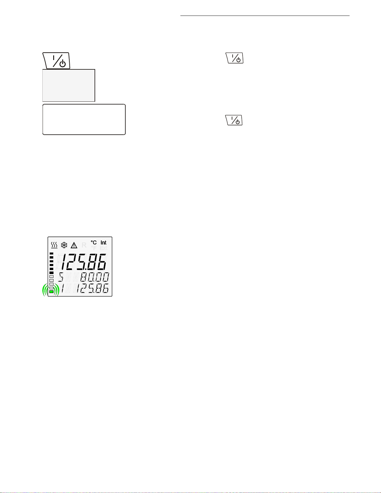
7. Manual operation
24.60
S 150.00
E -----
Setpoint1: 150.00°C
IntAct : 24.60°C
Power : 80 %
Control : intern
Circulator directly by pressing the mains switch or using a timer.
7.1. Start - Stop
Cryo-Compact Circulators
Start: Press the start/stop key .
The actual bath temperature is displayed on the VFD COMFORTDISPLAY.
The LCD DIALOG-DISPLAY informs about adjustments and
conditions on the Cryo-Compact Circulator (see example on the
left).
Stop: Press the start/stop key .
The V
Autostart: see chapter 8.1. Configuration
FD COMFORT-DISPLAY indicates the message „OFF“.
The Autostart function enables the start of the Cryo-Compact
7.2. Control of the cooling machine
With the mains switch turned on, the circulator automatically switches the
cooling machine off and on.
To ensure protection of the compressor, the software only switches the
compressor on after a delay of 200 seconds.
If the controller requires cooling performance during standstill of the
compressor, the segment at the bottom of the display blinks.
It is switched off , if:
- at internal control >Int<
the setpoint temperature is increased and the heat-up time calculated
by the controller is longer than the intended time of compressor
standstill (200 s).
- at external control >EXT<
the actual working temperature is increased by >5 °C
It is switched on, if:
- cooling is necessary for maintaining the bath temperature.
(possibly after the 200 s time delay).
Find Quality Products Online at: [email protected]
www.GlobalTestSupply.com
31
Page 32
Manual operation
Setpoints
>Setpoint1: 20.00°C
Setpoint2: 37.00°C
Sezpoint3: 70.00°C
Setpoints
Setpoint1: 20.00°C
Setpoint2: 37.00°C
>Setpoint3: 70.00°C
Setpoints
Setpoint1: 20.00°C
Setpoint2: 37.00°C
>Setpoint3: 85.00°C
25.83
S 85.00
E -----
1.
2.
3.
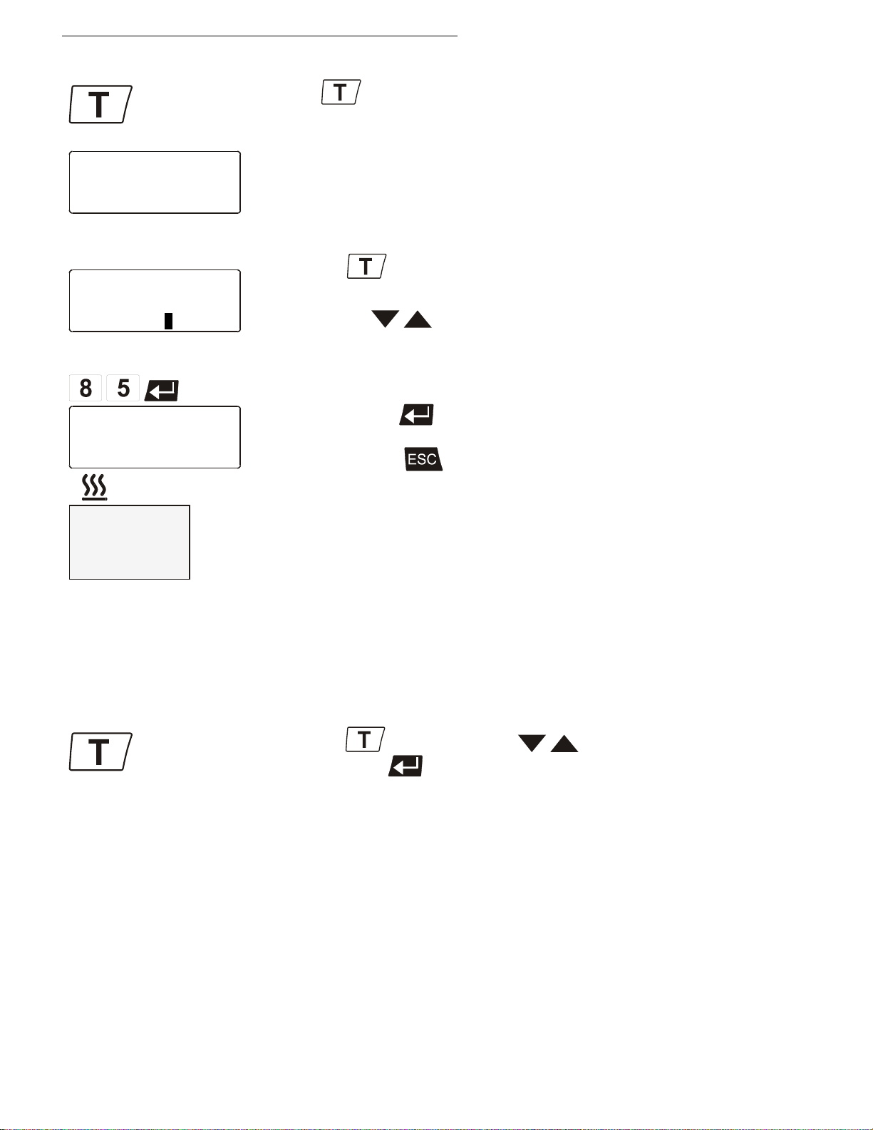
7.3. Setting the temperatures
Press the key to call up the menu for temperature selection.
Factory setting:
3 different working temperatures are adjustable. Their values are freely
selectable within the operating temperature range.
This setting may be carried out with the circulator being in the Start or
Stop condition!
Example: Setting working temperature „Setpoint 3“
Press the key.
The LCD DIALOG-DISPLAY indicates the valid settings.
Use the keys to select Setpoint 3.
(One segment of the line blinks)
Change the value to 85 °C.
In the >Start< condition this value is immediately used for controlling the
Notice: See SetMax: and SetMin:
in chapter 8.6. Limits on page 63
Example: Selecting the working temperature
• Press the key. Use the keys t o select setpoint 1, 2 or 3
The Cryo-Compact Circulator uses the new working temperature value
Use the numeral keypad to enter 8 and 5.
Then press enter to store the value.
The value remains visible on the LCD DIALOG-DISPLAY for about 10
seconds, or press t o update the display immediately.
working temperature.
The indication on the VFD COMFORT-DISPLAY is updated.
The heater control indicator blinks.
and press enter .
for temperature control.
Find Quality Products Online at: [email protected]
32
www.GlobalTestSupply.com
Page 33
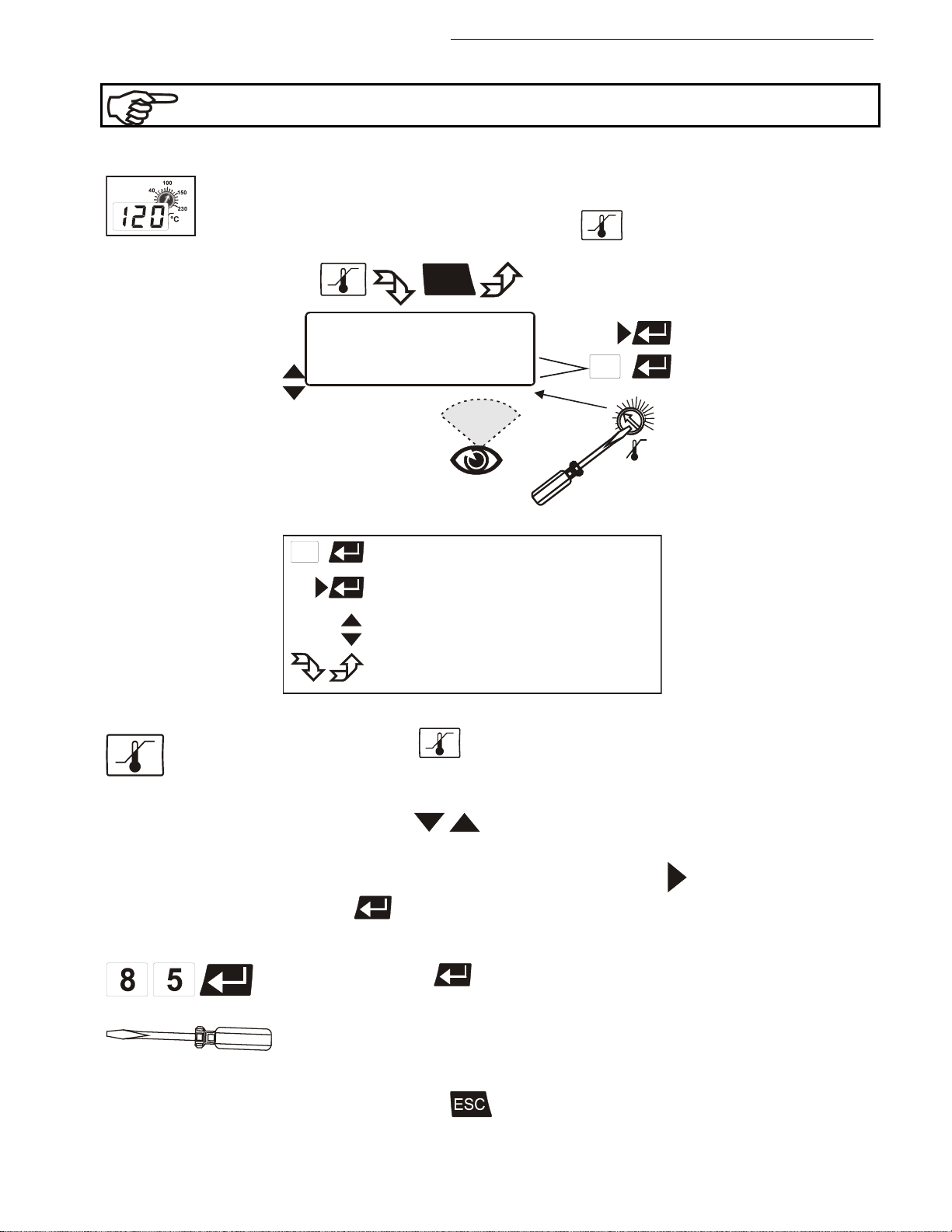
7.4. Safety installations, warning functions
ESC
1
Safety-values
>Warn-Type: Warning /Alarm
OverTemp : 85.00°C
SubTemp : -99.99°C
SafeTemp : 50.00°C
SafeSens : xx.xx°C
°C
°C
100
140
220060
20
Setting via keypad
Select parameter
Select menu item
Change menu level
scroll down / scroll up
1
1.
2.
Check the safety installations at least twice a year! (See page 19)
7.4.1. Excess temperature protection
Settings for the excess temperature protection according to IEC 61010-2-010
and for the high and low temperature warning functions are made
Cryo-Compact Circulators
in a menu that is called up with the key .
Legend:
Press the key
Example:
The LCD DIALOG-DISPLAY shows the valid settings (see example
above).
Use the keys to select the menu item.
Settings:
Warn-Type
enter (warning or alarm).
OverTemp and SubTemp: Use the numeral keypad to enter the value
and press enter .
SafeTemp: Set the new cut-out value using a screwdriver via the LCD
DIALOG-DISPLAY. (Example: 5 0 °C)
The value remains visible on the LCD DIALOG-DISPLAY for about 10
seconds, or press to update the display immediately.
: Select the parameter with the key and press
Find Quality Products Online at: [email protected]
www.GlobalTestSupply.com
33
Page 34
Manual operation
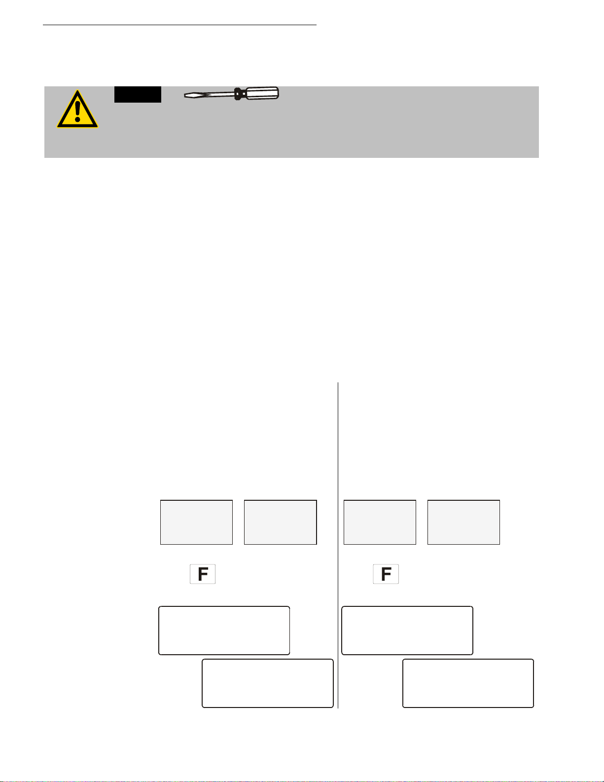
We disclaim all liability for damage caused by incorrect settings!
Warn-Type: >Warning<
Warn-Type: >Alarm<
XXXXX
WARNING
CODE 03
XXXXX
WARNING
CODE 04
Actual temperature
above high temperature value.
Actual temperature
below low temperature value.
XXXXX
ALARM
CODE 03
XXXXX
ALARM
CODE 04
Actual temperature
above high temperature value.
Actual temperature
below low temperature value.
Recommendation:
Set the excess temperature protection >SafeTemp< at 5 to 10 °C above the
working temperature setpoint.
Warning:
The excess temperature protection >SafeTemp< should be set below the flash point of
the bath fluid used.
In the event of wrong setting there is a fire hazard!
Warn-Type: >Warning< or >Alarm<
For the two menu items >OverTemp< and >SubTemp< choose between a
warning message being signaled or a complete shutdown of the main
functional elements such as heater and circulating pump being effected.
OverTemperature: SubTemperature:
If for a sensitive temperature application task adherence to a working
temperature value >Setpoint< is to be supervised, then set high and low
temperature warning values.
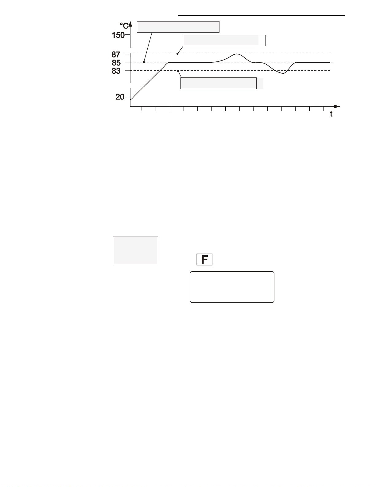
In the example below, the >Setpoint< of 85 °C is surrounded by the values
>OverTemp< 87 °C and >SubTemp< 83 °C. The electronics immediately
registers when the actual temperature attains a temperature out of the
limits and it follows a reaction according to what is set in the menu item
>Warn-Type<.
An audible warning (interval tone)
sounds and a meassage appears on
the VFD COMFORT-DISPLAY.
OverTemp SubTemp
Press
for help on the LCD.
A complete shutdown of heater and
circulating pump is effected.
An audible alarm (continuous tone)
sounds and a message appears on the
VFD COMFORT-DISPLAY.
OverTemp SubTemp
Press
for help on the LCD.
Find Quality Products Online at: [email protected]
34
www.GlobalTestSupply.com
Page 35
Cryo-Compact Circulators
OverTemp 87.0°C
SubTemp 83.0°C
Setpoint3 85.0°C
XXXXX
ALARM
CODE 14
Working temperature
exceeds the adjusted
safety temperature.
The warning functions are only triggered when the actual bath temperature,
after start from the „OFF“ or „rOFF“ mode, lies within the set limits for 3
seconds.
Setting range:
20 °C ... 220 °C
SafeTemperature: Indicated is the cut-out value set with a screwdriver on the
excess temperature protection device.
This safety installation is independent of the control circuit. When the
temperature of the bath fluid has reached the safety temperature, a complete
shutdown of the heater and pump is effected.
The alarm is indicated by optical and audible signals (continuous tone).
The following error message appears on the VFD COMFORT-DISPLAY:
SafeSens: Indicated is the temperature value of the safety sensor.
Press for help on the LCD
Find Quality Products Online at: [email protected]
www.GlobalTestSupply.com
35
Page 36
Manual operation
XXXXX
WARNING
CODE 40
Niveau level warning
Critical fluid level
Replenish the bath
tank with bath fluid
XXXXX
ALARM
CODE 01
Insufficient liquid
level or float is
defective.
Caution:
Explosion hazard at high temperatures!
7.4.2. Early warning system, low level protection
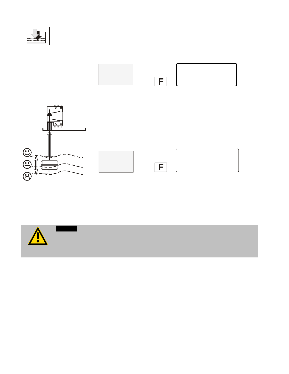
This low level protection is independent of the control circuit and is
divided in two sections.
(patented)
1. Switch in stage 1 recognizes a critical fluid level
An audible warning (interval tone) sounds and a message appears
on the VFD COMFORT-DISPLAY
Press
Refill bath fluid!
2. witch in stage 2 recognizes a low fluid level .
If stage 2 of the low level protection device (according to IEC 610102-010) is triggered, a complete shutdown of the heater and
circulating pump is effected.
A continuous alarm tone sounds and a message >ALARM< >CODE
01< appears on the VFD COMFORT-DISPLAY.
Press
Turn off the unit with the mains switch, refill bath fluid and turn the
unit on again!
Important: Check
the safety installations from time to time.
.
When adding bath fluid, always use the same bath fluid type that is already in the bath.
Bath oils must not contain any water and should be pre-heated approximately to the
current bath temperature!
Find Quality Products Online at: [email protected]
36
www.GlobalTestSupply.com
Page 37
8. Menu func ti ons
ESC
>Configuration
Control
Profile Start
Int.Programmer
Inputs/Outputs
Limits
Interface serial
ATCalibration
Pump
Main menu
Setting via keypad
Select parameter
Select menu item
Change menu level
scroll down / scroll up
1
1.
2.
Cryo-Compact Circulators
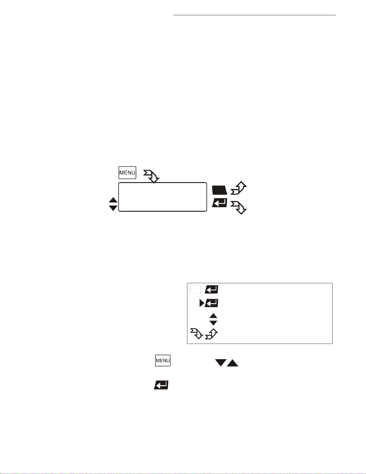
The term „menu functions“ refers to adjustments such as
Configuration of the Cryo-Compact Circulator
Internal and external control with adjustable control parameters
Start menu for the integrated programmer
Integrated programmer; 6 profiles with 60 sections each
Configurable inputs and outputs; analog recorder outputs, input for external
programmer or manipulated variable or flow rate
Determination of limits for all important setting ranges and capacity
variables
Online communication, with adjustable interface parameters
Absolute temperature calibration; sensor calibration
Electronically adjustable pump capacity
If the electronic module is not fitted, the item >inputs/o utputs<
will be missing in th e menu.
Legend
If you press , use the keys to move in menu level 1.
If the desired menu item is highlighted on the LCD DIALOG-DISPLAY (>),
press enter to change to menu level 2.
Find Quality Products Online at: [email protected]
www.GlobalTestSupply.com
37
Page 38
Menu functions
>Configuration
Control
Profile Start
Main menu
Configuration
>Setpoint : keypad /RS232/ext.Pt100/eprog
Autostart: off /on
OFF-Mode : pump off /pump on
Language : German /Englich
Reset : no /yes
Variable : control /serial/eprog
Unit : °C /°F
ESC
ESC
Setpoint1: 150.00°C
IntAct : 148.53°C
Power : 80 %
Control : intern
RS232 : 150.00°C
ExtAct : 145.30°C
Power : 80 %
Control : extern
-OFF-
S xxxx
I xxxx
R
Pt100 : 150.00°C
ExtAct : 145.30°C
Power : 80 %
Control : extern
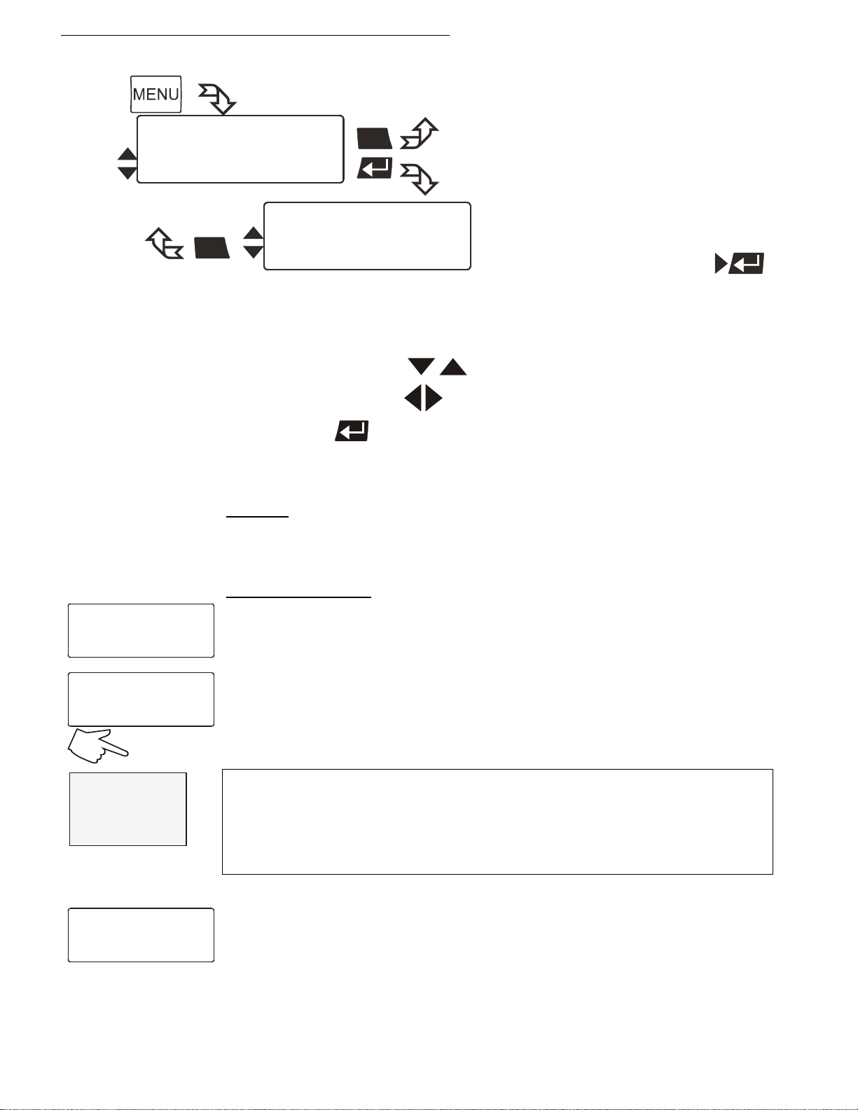
8.1. Configuration
1. Use the up/down keys to select the desired menu item.
2. Use the left/right keys to select the parameter (parameter blinks).
3. Press enter to store the new parameter.
Setpoint
The Cryo-Compact Circulator provides four possibilities for setpoint setting. The
selected mode is indicated in line 1 on the LCD DIALOG-DISPLAY.
Possible parameters:
keypad – Setpoint setting via keypad or via the integrated programmer.
(factory setting)
RS232 or RS485 - Setpoint setting via the serial RS232/RS485 interface
through a PC or superordinated data system.
In the header of the VFD COMFORT-DISPLAY an „
It indicates that remote control mode is set.
R“ illuminates.
RS232 or RS485: see menu > Serial interface < page 65.
Important:
Connect the Cryo-Compact Circulator to a PC using an interface cable.
Check the interface parameters of both interfaces (on Cryo-Compact
Find Quality Products Online at: [email protected]
38
Circulator and PC) and make sure they match.
(see 11.1. on page 75 )
ext.Pt100 – Setpoint setting via the analog socket „ext. Pt100“ using an
external temperature sensor or an appropriate voltage/current source.
www.GlobalTestSupply.com
Page 39
Cryo-Compact Circulators
eprog : 50.0°C
IntAct : 24.7°C
Power : 80 %
Control : intern
eprog – Can only be adjusted when an electronic module with analog
connections is used (option).
Setpoint setting via the analog interface REG+E-PROG connection with an
external voltage or current source or a programmer.
Important:
Connect the external voltage or current source or a programmer to the
circulator via the socket REG+E-PROG (see page 58).
In the menu >Inputs/Outputs< set the parameter >EPROG< and the input
variables (see page 59).
The E-Prog input can only be used either under menu item >Setpoint< or
under menu item >Variable< (page 40).
Autostart
Possible parameters:
on - AUTOSTART on
off - AUTOSTART off (Factory setting)
Note:
The temperature system has been configured and supplied by JULABO
according to N.A.M.U.R. recommendations. This means for the start mode, that
the unit must enter a safe operating state after a power failure (non-automatic
start mode). This safe operating state is indicated by „ OFF „, resp. R OFF on
the VFD-COMFORT-DISPLAY. A complete shutdown of the main functional
elements such as heater and circulating pump is effected simultaneously.
The values set on the Cryo-Compact Circulator remain stored, and the unit is
returned to operation by pressing the start/stop key (in manual control mode).
In remote control mode, the values need to be resent by the PC via the
interface.
Should such a safety standard not be required, the AUTOSTART function
(automatic start mode) may be activated, thus allowing the start o f th e
instrument directly by pressing the mains power switch or using a timer.
The AUTOSTART function can only be used, if setpoint setting is carried
out via >keyboard< or >eprog< or >ext. Pt100<.
Warning:
For supervised or unsupervised operation with the AUTOSTART function, avoid any
hazardous situation to persons or property.
The instrument does no longer conform to N.A.M.U.R. recommendations.
The safety and warning functions of the instrument should always be used to their
fullest capacity.
Find Quality Products Online at: [email protected]
www.GlobalTestSupply.com
39
Page 40

Menu functions
OFF-Mode
Normally the circulating pump is switched via the start/stop signal. However, if
circulation should be maintained also for the -OFF- condition, the parameter
>pump on< needs to be set.
Possible parameters:
pump off (factory setting)
pump on
Language
There are two options for the language of the LCD DIALOG-DISPLAY: German
or English.
Possible parameters:
deutsch / englisch German / English
Reset
Use this to reset all values to factory setting (except date and time).
Possible parameters:
yes
no (factory setting)
Variable - act
The variable corresponds to the extent to which the heater or cooling machine
of the Cryo-Compact Circulator is controlled. Heat or cold is applied to the bath
according to this variable. If this happens with the control electronics of the
Cryo-Compact Circulator , called >control< in this particular case, the bath
temperature is exactly heated and maintained constant at the adjusted
setpoint.
uating variable
Programming of variables for the parameters > serial < or > eprog < is only
accepted, if the unit is in Start mode.
Possible parameters:
control – The internal control electronics of the Cryo-Compact Circulator
controls the heater and cooling machine. Self-tuning is possible.
serial – The heater or cooling machine receives the control signal via the serial
interface. Self-tuning is not possible.
eprog - The heater or cooling machine receives the control signal via the E-
Prog input. Self-tuning is not possible. (option).
Important:
Set the parameter >EPROG< and the input variables also in the menu
>Inputs/Outputs< (see page 59).
Note:
The E-Prog input can only be used either under menu item >Setpoint<
(page 38) or under menu item >Variable< (see above).
Find Quality Products Online at: [email protected]
40
www.GlobalTestSupply.com
Page 41

Setpoints
>Setpoint1: 20.00°C
Setpoint2: 37.00°C
Sezpoint3: 70.00°C
Setpoints
>Setpoint1: 68.00°F
Setpoint2: 98.60°F
Setpoint3: 158.00°F
-OFF-
S xxxx
I xxxx
°F
Example:
°C °F
Cryo-Compact Circulators
Warning:
The working temperature range of the Cryo-Compact Circulator is determined during
configuration. If set to >Control<, this range cannot be exceeded.
If set to > serial < and > eprog <, heat or cold is applied to the bath without control.
The permissible maximum temperature can be exceeded. The user has to take
adequate precautions for temperature control.
Materials, such as gaskets or insulations for example, may be damaged or destroyed, if
the permissible maximum temperature is exceeded.
The safety and warning functions of the instrument should always be used to their
fullest capacity. (See page 33)
Unit
Temperature values can be displayed in the unit °C or °F.
With this change all adjusted temperature values are converted and displayed
into the new unit.
Possible parameters:
°C (factory setting)
°F
Find Quality Products Online at: [email protected]
www.GlobalTestSupply.com
41
Page 42
Menu functions
Main menu
Profile Start
Int. Programmer
>Control
Control
>ControlType:
Selftuning : once /always/off
Dynamic : aperio /normal
Xp : 1.0K
Tn : 100s
Tv : 5s
intern
Control
>ControlType: extern
Selftuning: once /always/off
CoSpeed : 0.0
Xp : 0.7K
Tn : 720s
Tv : 55s
Xpu : 5.0K
1
ESC
ESC
internal
external
1.
-OFF-
S xx.xx
E xx.xx
8.2. Control
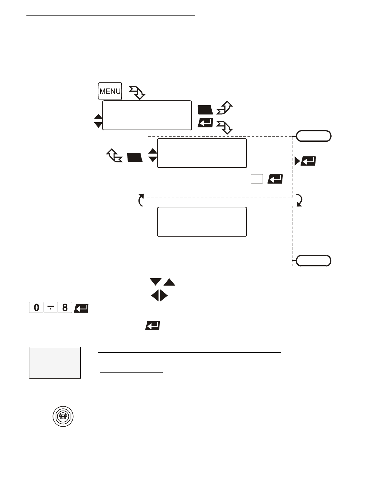
The Cryo-Compact Circulator is conceived for internal and external
temperature control. Switching is carried out in this submenu. Depending on
what is set, only the respective set of parameters is indicated.
Example: 0.8
Pt100
Use the keys to select the menu item.
2. With the keys select the parameter (parameter blinks)
or
use the numeral keypad to enter the numbers (number segment blinks).
3. Press enter to store the new parameter or value.
ControlType: Can only be adjusted in the -OFF- condition
Possible parameters:
intern internal temperature control
extern external temperature control with external Pt100 sensor
IMPORTANT:
Additional measures for external temperature control.
For external control and temperature measurement an external Pt100
sensor must be connected to the socket (7) on the rear of the CryoCompact Circulator .
Find Quality Products Online at: [email protected]
42
www.GlobalTestSupply.com
Page 43
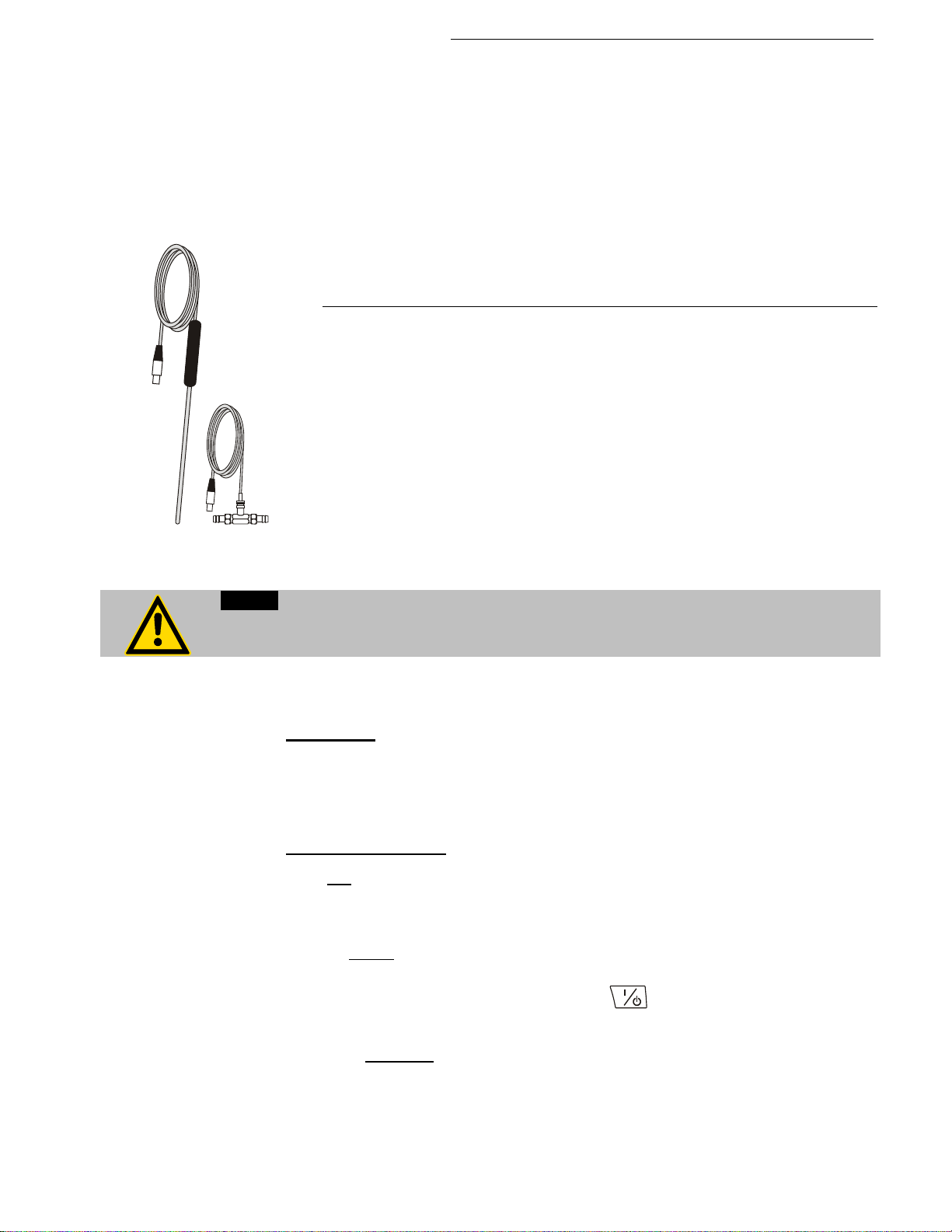
socket „ext. Pt100“ (see page 38).
circuit
Notice:
used for control purposes.
permanently.
Pt100 M+R
Cryo-Compact Circulators
Sensor calibration of the external Pt100 sensor is carried out in the menu
>ATCalibration<, with the > Status< set to >no< (see page 66).
Suggested adjustments for external temperature control:
AreaUp/ AreaDown and IntMax / IntMin
see chapter >Limits< on page 63.
External temperature control does not allow for setpoint setting via the
Accessory: Pt100 external sensor
Order No. Description Material Cable
8981003 200x6 mm Ø, stainless steel 1.5 m
8981005 200x6 mm Ø, glass 1.5 m
8981006 20x2 mm Ø, stainless steel 1.5 m
8981010 300x6 mm Ø, stainless steel 1.5 m
8981015 300x6 mm Ø, stainless steel / PTFE coated 3 m
8981013 600x6 mm Ø, stainless steel / PTFE coated 3 m
8981016 900x6 mm Ø, stainless steel / PTFE coated 3 m
8981014 1200x6 mm Ø, stainless steel / PTFE coated 3 m
8981103 Extension cable for Pt100 sensor 3.5 m
8981020 M+R in-line Pt100 sensor
The M+R in-line Pt100 sensor is a flow sensor and can be installed loop
Place the external sensor into the bath medium and securely fix the sensor.
Selftuning:
When performing an selftuning for the controlled system (temperature
application system), the control parameters Xp, Tn and Tv are automatically
determined and stored.
Possible parameters:
off - no selftuning.
The control parameters ascertained during the last identification are
once – single sel
The instrument performs a single selftuning of the controlled system
after each start with the start/stop key or after receiving a start
command via the interface.
always – continual selftuning
The instrument performs a selftuning of the controlled system whenever
a new setpoint is to be reached.
Use this setting only when the temperature application system changes
ftuning (factory setting)
Find Quality Products Online at: [email protected]
www.GlobalTestSupply.com
43
Page 44
Menu functions
°C
t
aperiodic
normal
setpoint
temp. stability
°C
t
aperiodic
normal
temperature ramp
temp. stability
°C
t
setpoint
5
3 0
Temp. intern
Temp. extern
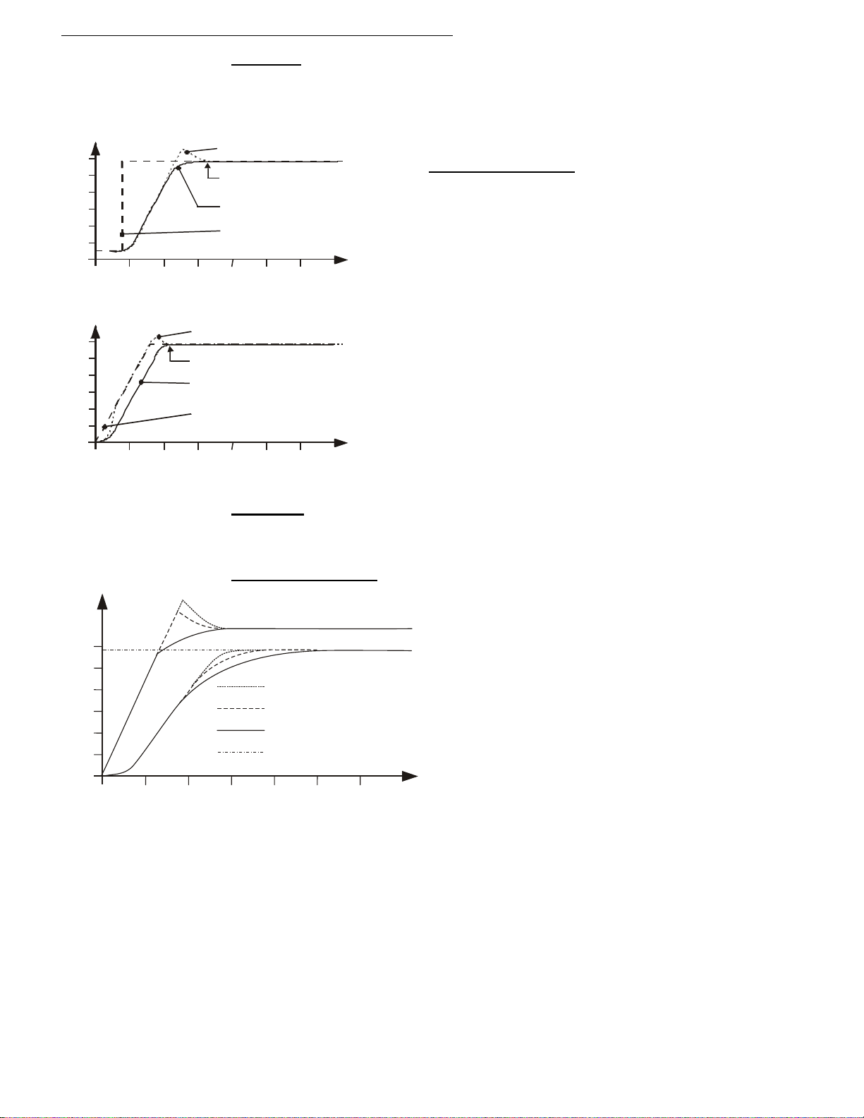
Dynamic:
This parameter affects the temperature pattern only in case of internal
control.
Possible parameters:
normal –Allows for reaching the setpoint faster,
but overshooting of up to 5 % is possible.
aperiodic – (factory setting)
Target temperature is attained without
overshooting.
With both adjustments an adequate
temperature stability is reached after
approximately the same time.
CoSpeed:
This parameter affects the temperature pattern only in case of external
control.
Possible parameters: 0 ... 5
During selftuning, the control parameters Xp, Tn
and Tv of a controlled system are automatically
determined and stored. Depending on the
controlled system, time for tuning can be
unequally longer. This controller layout allows
protection of sensitive objects requiring
temperature application.
As soon as a co-speed factor is set, it is
considered for calculating the control
parameters. As shown in the diagram, tuning
times become shorter the higher the co-speed
factor is, but overshooting can happen in the
internal system.
Control parameters – intern / extern
The control parameters preset in factory are in most cases adequate for
achieving an optimum temperature pattern for the samples requiring
temperature application.
Each parameter may be manually set via the keypad if necessary, to allow
optimum control performance.
Find Quality Products Online at: [email protected]
44
www.GlobalTestSupply.com
Page 45
Cryo-Compact Circulators
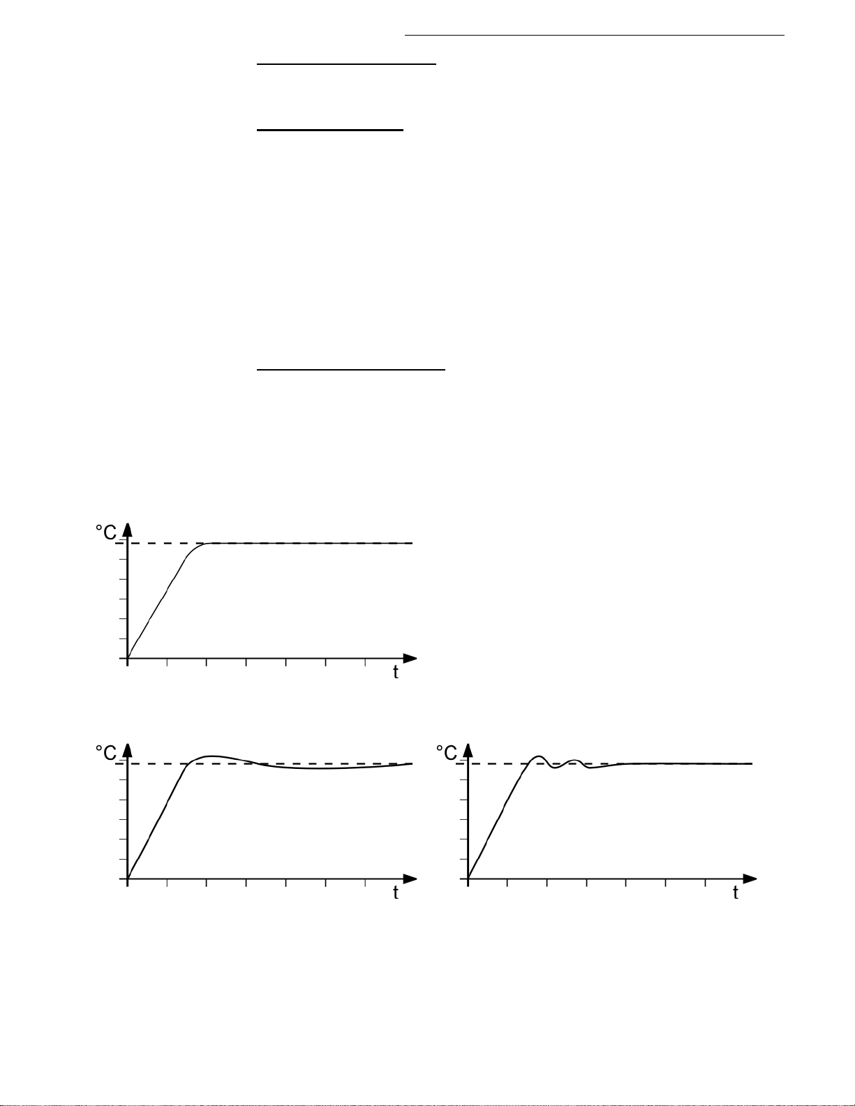
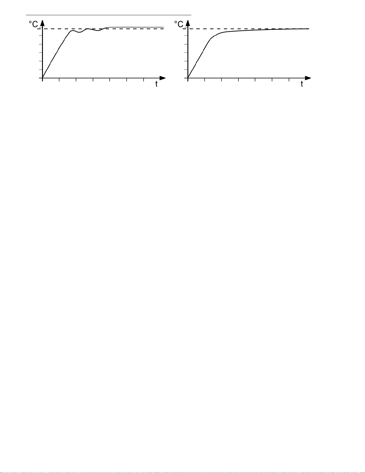
Xp too low
Tv/Tn too low
Xp too high or Tv too high
Tv/Tn too high or Xp too high
Setting range:
internal / external
0.1 ... 99.9 K
Setting range:
internal / external
3 ...9999 s
Setting range:
internal / external
0 ... 999 s
Setting range:
0.1 ... 99.9 K
Proportional range >Xp<
The proportional range is the range below the selected temperature value in
which the control circuit reduces the heating power from 100 % to 0 %.
Resetting time >Tn< (In
Compensation of the remaining control deviation due to proportional
regulation. An insufficient resetting time may cause instabilities to occur.
Excessive resetting time will unnecessarily prolong compensation of the
control difference.
Lead time >Tv< (Differential component)
The differential component reduces the control settling time. An insufficient
lead time will prolong the time required to compensate for disturbance effects
and cause high overshooting during run-up. An excessive lead time could
cause instabilities (oscillations) to occur.
Proportional range >Xpu<
The proportional range Xpu of the cascaded controller is only needed for
external control.
Optimization instructions for the PID control parameters:
tegral component)
optimum setting
Inappropriate settings may produce the following heat-up curves:
The heat-up curve reveals inappropriate control
settings.
Find Quality Products Online at: [email protected]
www.GlobalTestSupply.com
45
Page 46
Page 47
8.3. Star t of a profile
>Programmer Start
Main menu
Control
Int.Programmer
>Start Profile 0
at Step 0
Runs 1
Profile End Stdby /SetpPG/Setp 1/Setp 2/Setp 3
Start no /yes/time
1
ESC
ESC
>hour.min 11:15
Day.Mon 11.12
Year 2004
Start no /yes
1
>Programmer Start
1.
Cryo-Compact Circulators
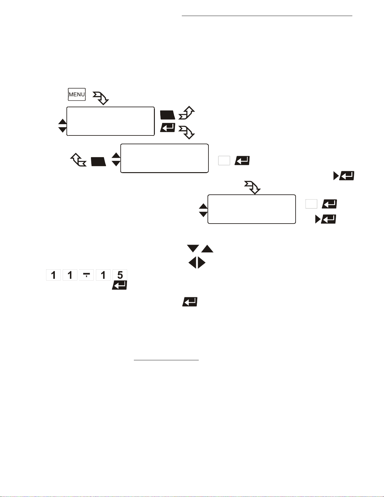
The start menu of the integrated programmer allows calling up and defined
starting of one of six previously stored temperature profiles. The profiles are
started manually or via the integrated timer.
Example: 11:15
Use the keys to select the menu item.
2. With the keys select the parameter (parameter blinks)
or
use the numeral keypad to enter the numbers (number segment
blinks).
3. Press enter to store the new parameter or value.
If the parameter time is selected, a further submenu opens for
setting the start time.
Possible parameters:
Start Profile 1 to 5
Select the profile that should be started.
at Step 1 t o 60.
Select the section with which the profile should be started.
Runs 1 to 99
Select the number of profile repetitions.
Start no / yes (manual start)
or
time (via integrated timer)
Find Quality Products Online at: [email protected]
www.GlobalTestSupply.com
47
Page 48
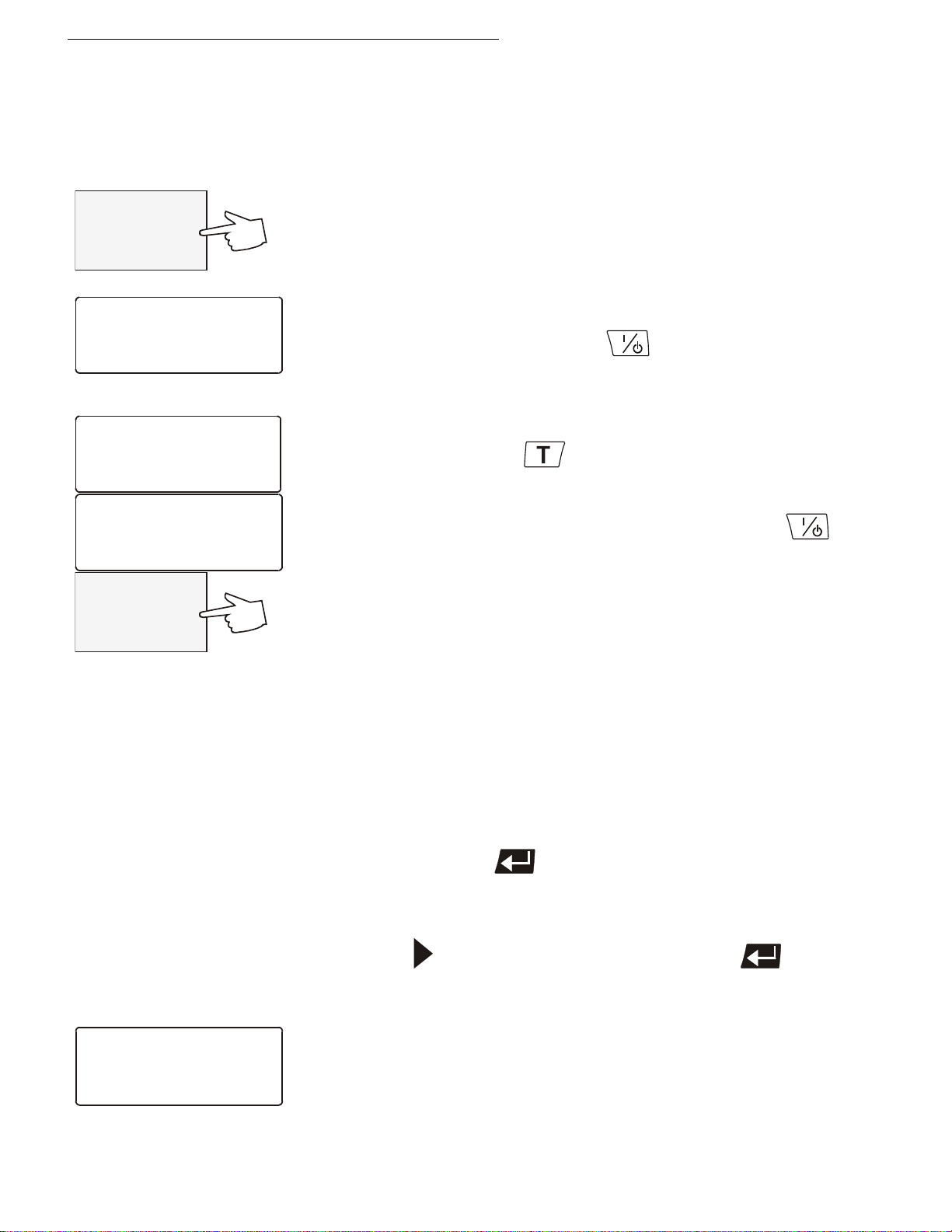
Menu functions
-OFF-
S 25.00
E -----
Setpoint3: 80.00°C
IntAct : 80.00°C
Power : 2%
Control : intern
Setpoint
Setpoint1: 25.00°C
>Setpoint2: 58.00°C
Setpoint3: 85.00°C
Setpoint2: 58.00°C
IntAct : 60.00°C
Power : 0%
Control : intern
60.00
S 58.00
E -----
Starttime: 06:00
Date : 15:12
*** wait ***
Acttime 02:34:45
Examples:
Profile End Stdby / SetpPG / Setp 1 / Setp 2 / Setp 3
This parameter is used to determine if the unit switches to the -OFFcondition at the end of a profile, or if temperature control is continued
and the working temperature setpoint that is be used in such case.
Stdby – If the end of the profile is reached, the Cryo-Compact
Circulator switches to the -OFF- condition. The VFD display
indicates the working temperature setpoint, that was displayed in line
2 already before the program was started (example: S 25.00 °C ).
SetpPG – (Setpoint of the ProGrammer) At the end of the profile, the
setpoint of the last program section is written to the position of
setpoint 3 (example: 80.00 °C) and indicated in line 1 of the LCD
display. The Cryo-Compact Circulator operates and controls this
temperature until the Start/Stop key
profile is started.
Setp 1, Setp 2, Setp 3 – („Setp“ short for Setpoint)
Before starting the programmer, a temperature value is set for one of
the three setpoints in the
(example: Setpoint 2 58.00 °C)
The Cryo-Compact Circulator operates and controls this
temperature at the end of the profile until the Start/Stop key
pressed or a new profile is started.
Start no / yes (manual start)
or
time (via integrated timer)
When selecting the parameter time, a new submenu is called up for
entry of the start time.
A flashing segment indicates that a start time needs to be entered.
hour.min Start time
Day.Mon day and month
Year year
menu.
is pressed or a new
is
Set each entry with enter .
Start no / yes
A flashing line indicates that the parameter „yes“ needs to be entered.
Press the key to select the parameter and press enter
The temperature system switches to waiting mode and a flashing line
„wait“ appears on the LCD DIALOG-DISPLAY. The start time and actual
time are permanently indicated on the display.
Find Quality Products Online at: [email protected]
48
www.GlobalTestSupply.com
.
Page 49
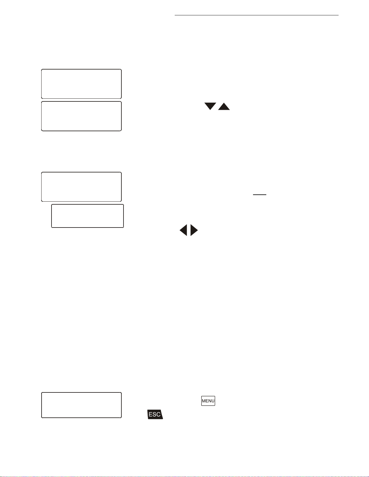
Cryo-Compact Circulators
Setp. : 125.8°C
IntAct: 124.7°C
Prof. : 4 Step: 12
Remain: 00:03:45
Setp. : 125.8°C
IntAct: 124.7°C
Prof. : 4 Step: 12
All : 00:03:45
Setpoint : 125.8°C
IntAct : 124.7°C
Prof : 4 Step:12
S12:150:00 h:m 01:10
>Edit Profile: 4
Step: 12
Setp: 150.00°C
Time [hh:mm] 01:10
Edit
>Edit Profile: 1
Step: 6
Setp: 100.00°C
Time [hh:mm] 01:05
Edit
Examples:
Indication after successful start:
The started programmer displays the actually calculated setpoint in line
1. The value changes until the final temperature of the section is reached
(temperature ramp).
st
1
line: Setpoint of the programmer
nd
2
line: Actual temperature value
at internal control = IntAct: xxx.xx
at external control = ExtAct: xxx.xx
rd
3
line: Selected profile and the actual section (step).
th
line: With the keys the following information can be
4
displayed in line 4.
• Remaining time of the actual section (standard display)
• Remaining total time: Profile x number of repetitions
(All: Days/hours:minutes:seconds)
Particularitys:
1. If a total time of more than 999 days is calculated, only the hours are
displayed on the unit.
(All: hours:minutes:seconds)
2. If the time period of a section is edited after start, then the remaining
total time can no longer be displayed.
8.3.1. Edit after start
• The data of a section as stored under „Edit Profile“.
Use the keys to successively indicate the sections of a profile.
Unused sections or incorrect data are skipped.
A JULABO programmer of generation II allows editing of a running
profile. A programmer of the previous generation requested the profile to
be interrupted, edited and then started again.
Start and quit the edit mode:
• After start, press the
Press to quit the edit mode.
key to enter the submenu „Edit Profile“.
Find Quality Products Online at: [email protected]
www.GlobalTestSupply.com
49
Page 50
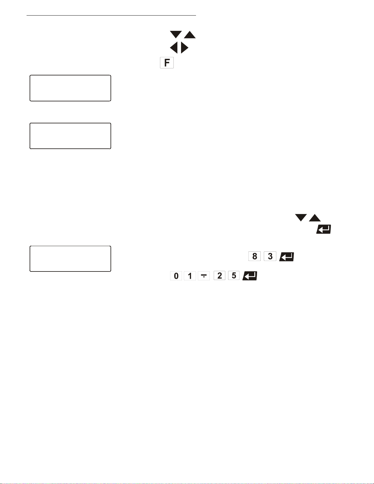
Menu functions
>Edit Profile: 1
**Step is deleted **
Setp: °C
Time [hh:mm]
Edit
>Edit Profile: 1
** Step is active **
Setp: 100.00°C
Time [hh:mm] 01:05
Edit
Edit
Step: 6
>Setp: 83.00°C
time [hh:mm] 01:25
Deleting a complete section:
• Use the keys to move to line 2.
• Use the keys t o choose the desired section.
• Press the
If the desired section is already chosen, the section is deleted even if the
cursor > is in line 1, 3 or 4.
Deletion is indicated in the respective line of the LCD display:
** Step is deleted **
The section that is currently processed cannot be deleted. If you still
try it, the message ** Step is active ** appears on the
LCD display.
Changing a section:
key to delete the complete section.
The values in lines 3 and 4 can be changed, even on the section that
is currently processed.
• In the input window, select the menu item with the keys .
• Use the numeral keypad to enter the numbers and press enter .
Examples:
Setpoint: target temperature 83 °C
Time time period 1 hour:25 minutes
Particularity for changes in a section that is currently in process.
If the target temperature is changed, the slope of the ramp is
automatically calculated on basis of the remaining time of the
section.
If the time period is changed, the slope of the ramp is automatically
calculated on basis of the new total time of the section.
Find Quality Products Online at: [email protected]
50
www.GlobalTestSupply.com
Page 51
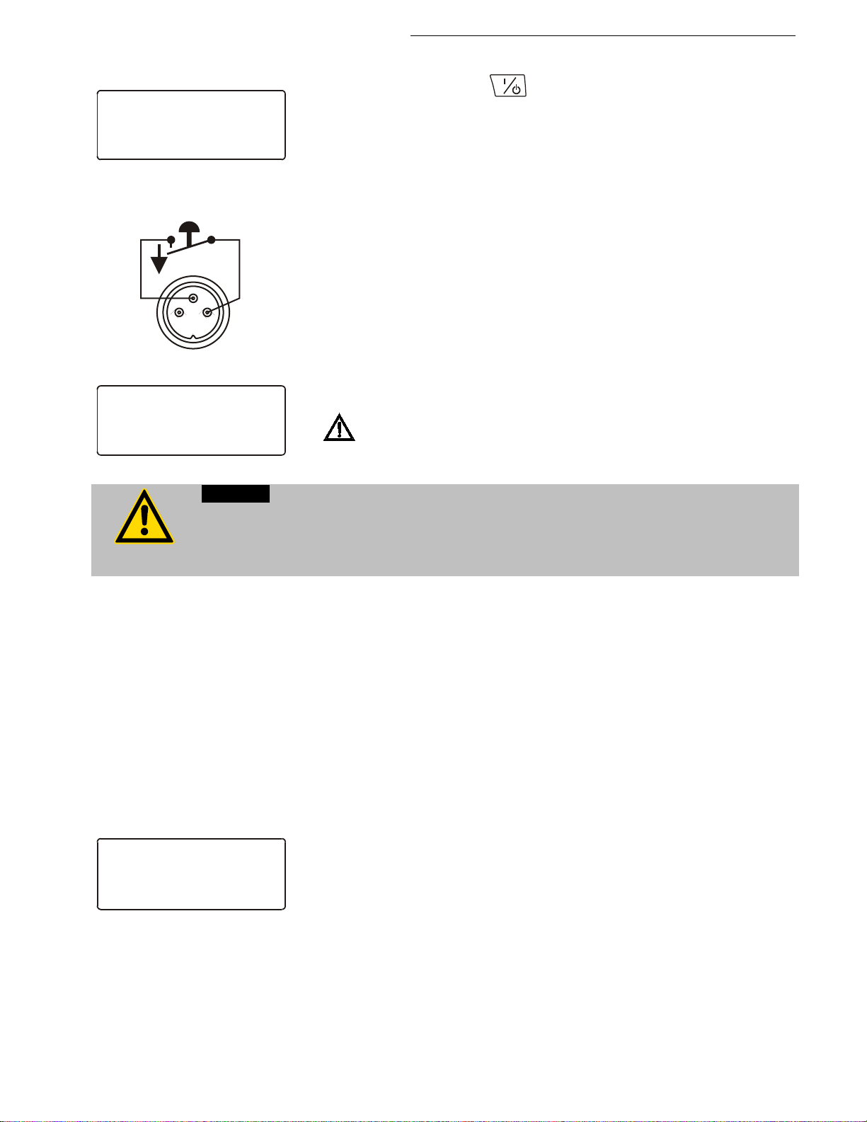
8.3.2. Interrupting a profile
Setp. : 125.80°C
IntAct: 124.70°C
Prof. : 4 Step:12
*** pause ***
Setp. : xxx.xx°C
IntAct: xxx.xx°C
Prof. : 4 Step:12
*** STAND-BY ***
Warning:
See Warning page 39.
Starttime: 06:00
Date : 15:12
*** wait ***
Acttime 02:34:45
AK
1
2
3
STAND-BY
Press the start/stop key to interrupt or continue a profile.
Cryo-Compact Circulators
The setpoint and time period set for the corresponding section are
thus stopped at the values presently achieved.
The instrument is put on hold and the message „pause“ flashes on
the LCD DIALOG DISPLAY.
A profile can be interrupted or restarted by an external emergency
shut-off.
Important:
For this, in the menu >Inputs/Outputs< the menu item >Ext. StBy <
must be set to >activ< (see page 61)
and in the
page 39).
menu >Configuration< >Autostart< needs to be set (see
Following a power interruption, it would be possible in this condition for the instrument
to restart automatically. The safety and warning functions of the instrument should
always be used to their fullest capacity.
8.3.3. Interruption after a power failure
„AK”.
The instrument is put on hold and the message „Stand-By“ flashes
on the LCD DIALOG-DISPLAY.
Notice: This is not an actual emergency switch-off.
There is every possibility to operate the programmer safe to power
failures.
Important:
For this in the menu >Configuration< >Autostart< needs to be set (see
page 39).
If the AUTOSTART function is activated, the programmer starts
again at a point approx. 20 seconds before the interruption took
place. However, an uncontrolled change of the bath temperature
happened.
Power failure when the instrument is on hold if start is effected via
Setpoint control and timer are interrupted by breaking the contact
the built-in tim er:
If the starting time is not yet reached, the programmer is put on hold
again.
If the starting time is exceeded, the programmer starts immediately.
Find Quality Products Online at: [email protected]
www.GlobalTestSupply.com
51
Page 52
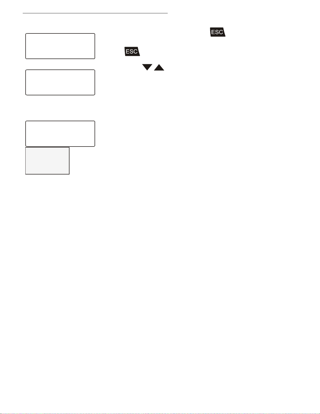
Menu functions
Setp : 125.80°C
IntAct: 124.70°C
Prof. : 4 Step:12
Remain: 00:03:45
>Start Profile x
at Step x
Runs 1
Start no
Programmer Start
Setpoint1: 150.00°C
IntAct : 83.24°C
Power : 0 %
Control : intern
-OFF-
S 150.00
E -----
8.3.4. Termination of a profile
A profile can be terminated by pressing . The programmer
switches back to the Start menu.
• Press again to quit the menu
Example:
or
use the keys
The start of another temperature profile can now be prepared if
necessary.
Interruption after a power failure
In case of a power failure, the reaction of the Cryo-Compact Circulator
is the same as when switched off and on again with the mains switch.
The LCD DIALOG-DISPLAY gives information on the adjustments and
conditions of the Cryo-Compact Circulator .
The VFD COMFORT-DISPLAY indicates "OFF".
to remain in the Start menu.
Find Quality Products Online at: [email protected]
52
www.GlobalTestSupply.com
Page 53
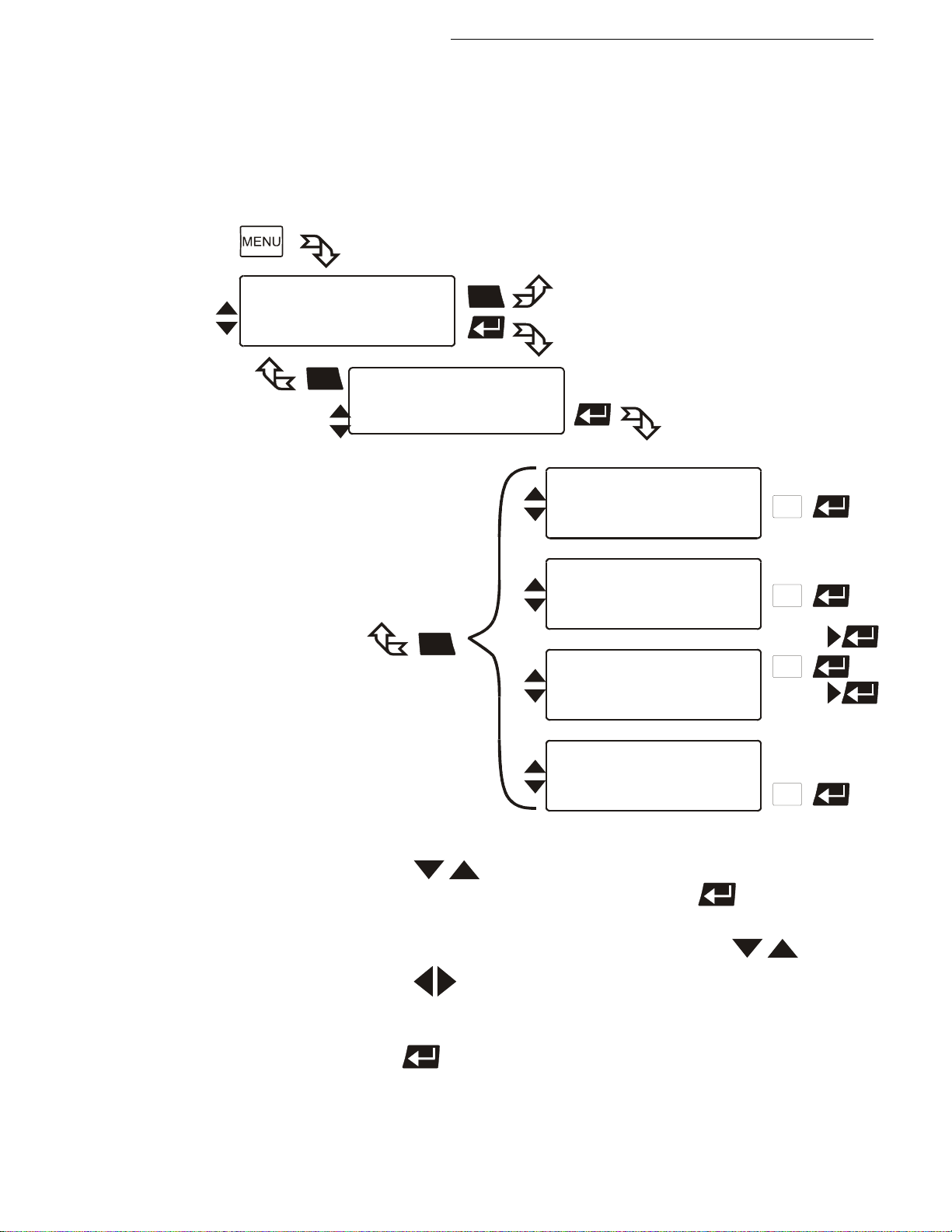
8.4. Integrated programmer
The integrated programmer allows any desired temperature program
Main menu
Inputs/Outputs
Limits
>Int. Programmer
>Edit Profile: 0
Step: 0
Setp: °C
Time [hh:mm]
>Delete Prof. 0
from Step 0
to Step 60
delete no /yes
>Print Profile 0
Print yes /no
>hour.min 14:24
Day.Mon 07.12
Year 2006
14:24:36
Int. Programmer
>Edit
Delete
Print
Set Clock
ESC
111
1
ESC
ESC
Edit
Delete
Print
Set Clock
1.
2.
3.
4. Press enter to store the new parameter or value.
sequences to be realized. Such a temperature sequence is called profile. A
profile consists of individual sections defined by duration (t:) and target
temperature. Target temperature is the setpoint (T:), that is achieved at the end
of a section. The programmer uses time and temperature difference values
within a section to calculate a temperature ramp.
Cryo-Compact Circulators
Use the keys to select the desired menu item in menu level 2
on the LCD DIALOG-DISPLAY (>) and press enter to change to menu
level 3. An input window opens for each menu item.
In the input window, select the menu item with the keys .
Use the keys to select the parameter (parameter blinks)
or
use the numeral keypad to enter the numbers (number segment blinks).
Find Quality Products Online at: [email protected]
www.GlobalTestSupply.com
53
Page 54
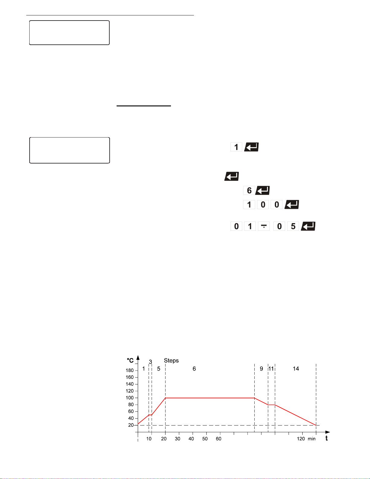
Menu functions
Int. Programmer
>Edit
Delete
Print
Set Clock
>Edit Profile: 1
Step: 6
Setp: 100.00°C
Time [hh:mm] 01:05
Edit
Edit Compile profiles
Display sections
Important: Also a running profile can be changed.
See „Edit after start“ page 49
Delete Delete sections
Print Print a programmed profile
Set clock Set the real time on the instrument
Example:
Compile profiles:
A flashing segment indicates that a number needs to be entered.
Under submenu „Edit Profile“ enter a profile number.
Six profiles may be stored (nos. 0 to 5).
Edit Profile: Profile No.1
Then programme the desired values for each section.
Use the keypad to set section number, target temperature and time
period. Set each entry with enter .
Step: Section No. 6
Setpoint: target temperature - 100 °C
Time time period - 1 h:05 minutes
When the program is running, only sections having complete
information for target temperature and time period are considered.
It makes sense, to leave out section numbers in the profile, in order
to use them later for corrections in the profile
Example:
Step (No.) 1 3 5 6 9 11 14
Setpoint (°C) 50 50 100 100 80 80 20
Time (h.m) 00:08 00.02 00:10 01:05 00:10 00:05 00:30
Important:
If a time of 00:00 is set for a profile, the profile is continued with the
next section only after the setpoint temperature (±0.2 °C) is
reached.
Find Quality Products Online at: [email protected]
54
www.GlobalTestSupply.com
Page 55
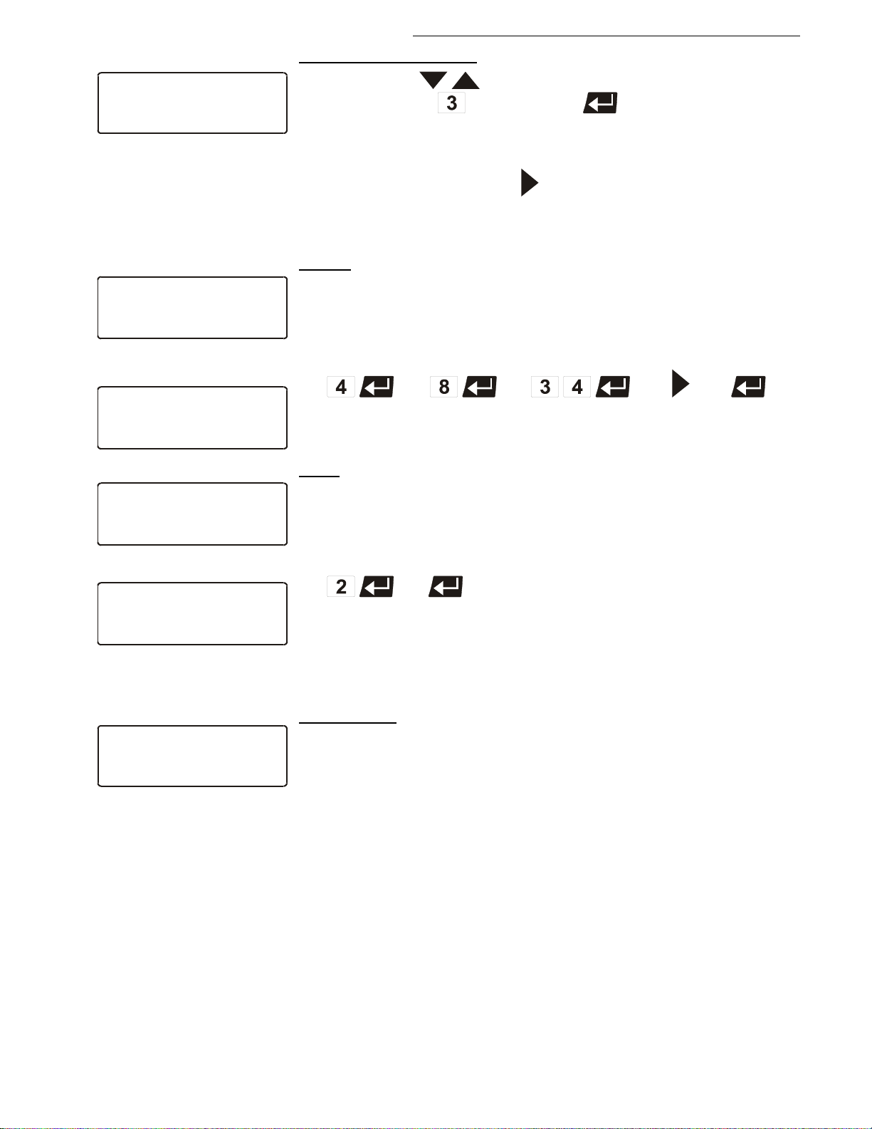
Cryo-Compact Circulators
>Edit Profile: 1
Step: 3
Setp: 50.00°C
Time [hh:mm] 00:02
Edit
Display sections (Step):
>Delete Prof. 4
from Step 8
to Step 34
delete yes
Delete
>Delete Prof. 4
from Step 8
****** delete ******
Delete
>Print Profile 2
Print yes
Print
>Print Profile 2
****** print *******
Print
>hour.min 14:24
Day.Mon 07.12
Year 2006
14:24:36
Set Clock
1 Use the keys to select the submenu „Step“, enter the
desired number and press enter
or
2 If the submenu „Step“ is selected, section by section can be shown in
ascending order by the key .
Each previously set value is displayed.
Example:
Example:
Delete:
A flashing segment indicates that the respective profile number
needs to be entered in which one or more consecutive sections are
to be deleted.
Example:
Delete step 8 to step 34 in profile 4.
Line 4 indicates the deletion.
Print:
Each profile may be printed via the serial interface for control or
documentation.
A flashing segment indicates that the number of the profile to be
printed needs to be entered.
Example: Print profile 2
ye
Printing is indicated in line 2.
s
yes
Setting clock
The integrated clock allows starting a profile at any date and time.
The clock is preset in the factory.
Lines 1 to 3:
Check for correctness of the preset date and time and correct if
necessary.
The time is diplayed permanently in line 4.
Find Quality Products Online at: [email protected]
www.GlobalTestSupply.com
55
Page 56
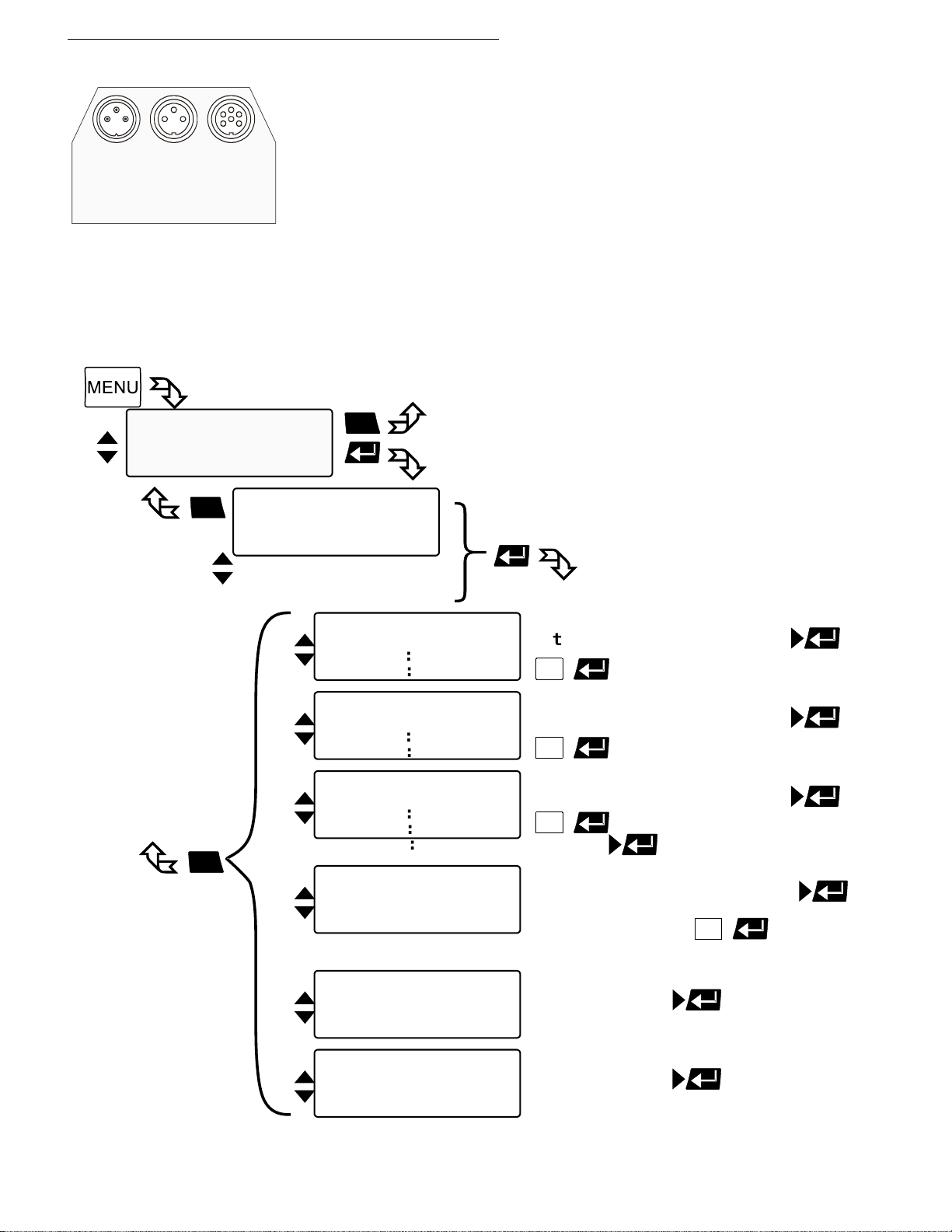
Menu functions
ALARM
REG+
E-PROG
STAND-BY
missing in the menu.
Main menu
Limits
Interface serial
>Input/Output
Inputs/Outputs
>Chan.1 : ActInt
EPROG : Setpoint
Ext.StBy : inactiv
Alarmout : StdBy
Chan.2 : Setpoint
Chan.3 : Power
Output Chan.1
tExt/Power/Setpoint
:
:
>Value of: ActInt /Ac
0V = -50.00°C
10V = 200.0°C
Output Chan.2
tExt/Power
: : >Value of: Setpiont /ActInt/Ac
0V 0.00°C
10V 100.00°C
Output Chan.3
tExt/ActInt
:
:
:
>Value of: Power /Setpoint/Ac
0mA 0%
20mA 100%
Region: 0-20mA /4-20mA
Input EPROG
(%)/FlowRate(L/min)
REM: % / L/min
REM: % / L/min
>Value as: Setpoint /Variable
Signal : Voltage /Current
H Value 200.00°C
Setpoint : xx.xx°C
AlarmOut
>Function: StdBy /Alarm/Al+StdBy
Type : normal /invers
ESC
ESC
1
1
1
ESC
Input Standby
>Status : inactiv /activ
1
L Value -50.00°C REM: % / L/min
8.5. Analog inputs/outputs
In order to use the analog inputs and outputs, the Cryo-Compact
Circulator must be equipped with the electronic module available as
option.
Order No. 8 900 100 Electronic module
This submenu enables setting of the input and output values for the
programmer input and the temperature recorder outputs of socket
REG+E-PROG.
The >STAND-BY< input and the >ALARM< output are configurable.
If the electronic module is not fitted, the item >inputs/outputs< will be
Find Quality Products Online at: [email protected]
56
www.GlobalTestSupply.com
Page 57
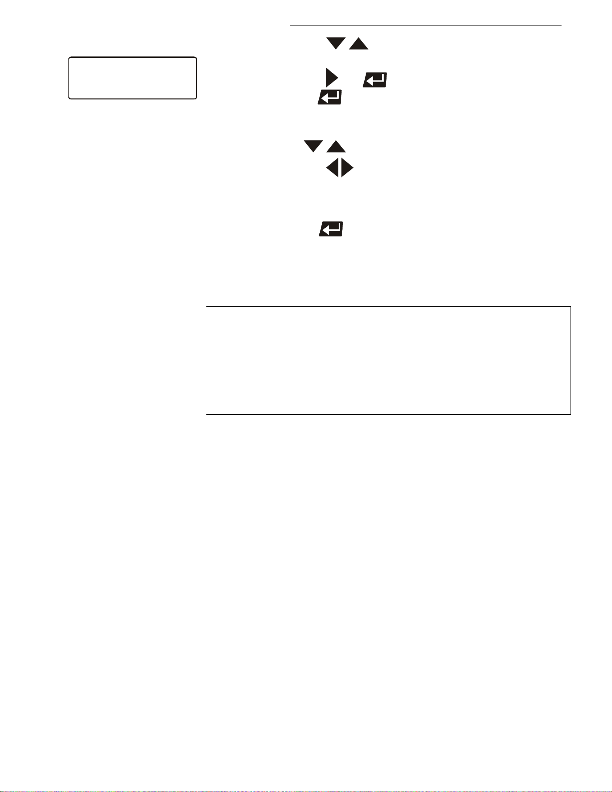
Cryo-Compact Circulators
Inputs/Outputs
>Chan.1 : ActInt
EPROG : Setpoint
Ext.StBy : inactiv /activ
AlarmOut : StdBy
Chan.2 : ActInt
Chan.3 : Setpoint
1.
2.
3.
4.
5.
Menu level 2
Use the keys to select the desired (>) menu item in
menu level 2 on the LCD DIALOG-DISPLAY.
Use the keys and to store the desired parameter or
press enter to enter menu level 3. An input window opens
for each menu item.
In the input window in menu level 3 select the menu item with
the keys .
Use the keys to select the parameter (parameter blinks)
or
use the numeral keypad to enter the numbers (number
segment blinks).
Press enter to store the new parameter or value.
Menu level 2
Channel 1 volt
Channel 2 voltage out put for recorder (V))
Channel 3 curr ent output for recorder (mA)
EPROG external programmer input
External standby Standby input
(for external emergency switch-off)
Alarm output Output for external alarm signal
age output for recorder (V)
Find Quality Products Online at: [email protected]
www.GlobalTestSupply.com
57
Page 58
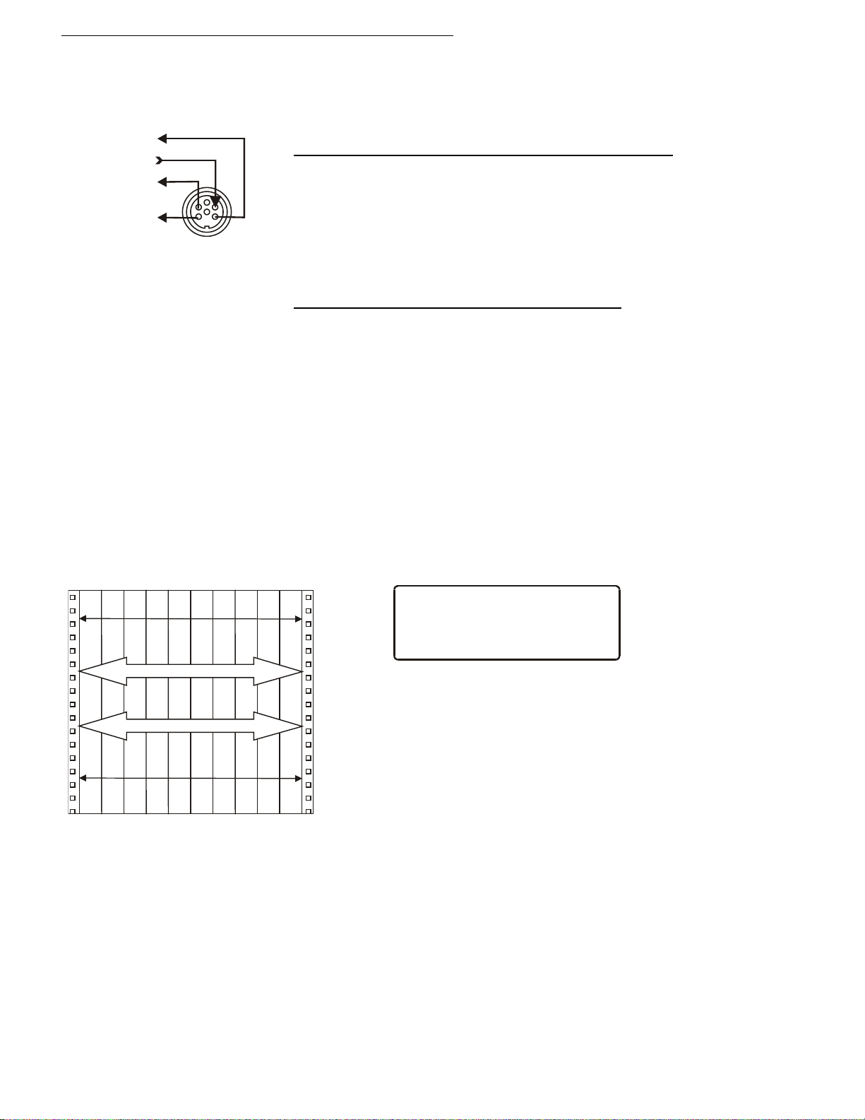
Menu functions
0 V
0 mA
20 mA
4 mA
10 °C
210 °C
197 °C
202 °C
∆ Τ =
5 K
∆ Τ =
200 K
>Value of : ActInt
0V = 10°C
10V = 210°C
Chan.1
CHANNEL 1
CHANNEL 3
CHANNEL 2
REG+E-PROG
EPROG
8.5.1. REG+E-PROG – temperature recorder outputs
REG+E-PROG (11):
Outputs of the connector
1. First define the desired output value for channels 1 to 3:
ActInt internal actual temperature value (bath temperature)
ActExt external actual temperature value (external sensor)
Power periodic or intermittent heating or cooling
Setpoint active setpoint temperature
(Setpoint1, 2, 3,/ integr. programmer /external programmer)
2. Then select the display size for channels 1 to 3:
Voltage outputs channels 1 and 2
Assign the voltage values of 0 V to the lowest and 10 V to the highest
necessary temperature or power rating required as an output value
(°C / %).
Current output channel 3
Assign the current values 0 mA or 4 mA to the lowest and 20 mA to
the highest temperature or power rating required as an output value
(°C / %).
3. The current output (chanell 3) offers 2 ranges for selection:
0 to
20 mA or 4 to 20 mA
Examples:
lowest temperature value: 10 °C
highest temperature value 210 °C
Fig. shows 200 °C scaled to paper width
rise: 50 mV/°C
lowest temperature value: 197 °C
highest temperature value: 202 °C
Fig. shows 5 °C scaled to paper width
rise: 2000 mV/°C
Find Quality Products Online at: [email protected]
58
www.GlobalTestSupply.com
Page 59
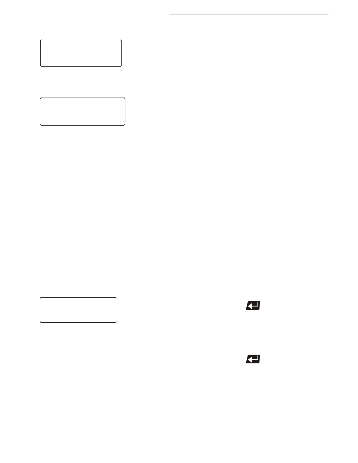
8.5.2. REG+E-PROG - programmer input
Menu >Configuration<
Configuration
>Setpoint : eprog
Keypad/RS232/extPt100
Autostart: off
Standby : pump off
Language : english
Reset : no
Variable : Control /
serial/
eprog
>Value as: Flowrate
Signal : Voltage
L Value 0.0L
H Value 50.0L
Flowrate: xx.xL
Setpoint/Variable
(Liters/Minute)
Input EPROG
>Value as: Setpoint
Signal : Current
L Value : 20.0°C
H Value : 300.0°C
Setpoint: 50.0°C
Input EPROG
Example:
Menu >Inputs/Outputs<
Cryo-Compact Circulators
E-PROG - Input
Setting needs to be carried out, if
1. setpoint programming is to be made via an
external voltage or current source or
programmer
For this, in the menu >Configuration< first set
the menu item >Setpoint< to >eprog<.
2. the heater variable should be controlled via an
external control pulse.
For this, in the menu >Configuration< set the
menu item > Variable.< to >eprog<.
3. the signal of an external flow meter should be
registered.
The E-Prog input can only be used either under menu item
>Setpoint< or under menu item > Variable <.
If the input is neither occupied by >Setpoint< or > Variable <, the
signal of a flow meter can be connected.
First set menu >Configuration<, then menu >Inputs/Outputs<.
Example:
• Connect the external voltage or current source or programmer to
socket (12) REG+E-PROG of the circulator.
Selecting the signal:
The programmer (E-PROG) input of the circulator can be matched to
the output signal of the external voltage or current source.
Voltage voltage input
Current current input
„L Value“ - Setting the LOW value: (See below
First adjust and set the lowest voltage or current on the external
voltage or current source (e.g. 0 V or 0 mA).
Then after approx. 30 secs enter the corresponding temperature
value (e.g. 20.00°C).on the circulator by pressing the appropriate
buttons on the keypad and press enter to set.
)
„H Value“ - Setting the HIGH value: (See below
First adjust and set the highest voltage or current on the external
voltage or current source (e.g. 10 V or 20 mA).
)
Then after approx. 30 secs enter the corresponding temperature
value (e.g. 300 °C).on the circulator by pressing the appropriate
buttons on the keypad and press enter to set.
• Set the external voltage or current source output for the equivalent of
50 °C temperature setpoint.
• The value adjusted and set on the external programmer is displayed
Find Quality Products Online at: [email protected]
in line 4 of the LCD DIALOG-DISPLAY for control purposes.
www.GlobalTestSupply.com
59
Page 60
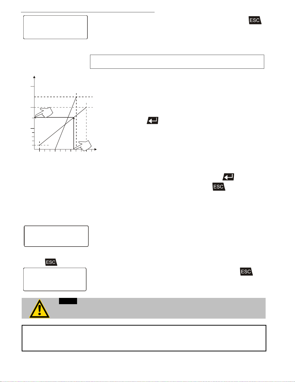
Menu functions
Eprog : 50.0°C
IntAct : 24.7°C
Power : 80 %
Control : intern
>Value as: Setpoint
Signal : Voltage
L Value : 20.0°C
H Value : 200.0°C
Setpoint: 152.0°C
Input EPROG
Eprog : 152.00°C
IntAct : 50.76°C
Power : 100 %
Control : intern
Notice:
Important:
combination (working temperature range see technical specifications on page 13)
20
40
60
80
100
200
300
250
150
°C
1 2 3 4 5 6 7 8 9 10 V
2 4 6810 14 18 20 mA
A
B
After returning the LCD display to standard display by pressing
the temperature value adjusted and set on the external voltage or
current source is displayed in line 1
(Example: Eprog : 50.00 °C).
This EPROG input enables the use of different voltage and current
values as program parameters.
• L Value“ - Setting the LOW value: (See below
)
1) Adjust and set the lowest desired value on the voltage or
current source resp. (Example A: 1 V).
Wait appr. 30 seconds.
2) Assign a lower temperature threshold value to this adjusted
voltage/current value by pressing the appropriate buttons on the
keypad of the instrument (Example A: 20 °C ) and set by
pressing enter
• „H Value“ - Setting the HIGH value: (See below
.
)
1) Adjust and set the highest desired value on the voltage or
current source resp. (Example A: 10 V).
Wait appr. 30 seconds.
2) Assign an upper temperature threshold value to this adjusted
voltage/current value by pressing the appropriate buttons on the
keypad of the instrument
(Example A: 200 °C) and set by pressing enter .
• Return to the standard display by pressing .
Example B in the diagram serves to illustrate that the end point
values are freely selectable (Ex: 8 mA and 16 mA).
Example out of diagram A:
• Adjusting the voltage source for an output of 7.6 V!
Line 5 of the LCD DIALOG-DISPLAY shows the externally set setpoint
value. The instrument calculates this value from the rise angle of the two
pre-decided end points (in example A: 7.6 V correspond to an external
setpoint temperature of 152.0 °C ).
After returning the LCD display to standard display by pressing ,
this value is displayed in line 1
(Example: EPROG 152.00 °C).
If this adjustment is not correctly performed at two different points, the setpoint setting
will be incorrect.
Find Quality Products Online at: [email protected]
The usable temperature range between > L Value < and > H Value < is limited to the
configured working temperature range of the Cryo-Compact Circulator resp. of the unit
60
www.GlobalTestSupply.com
Page 61
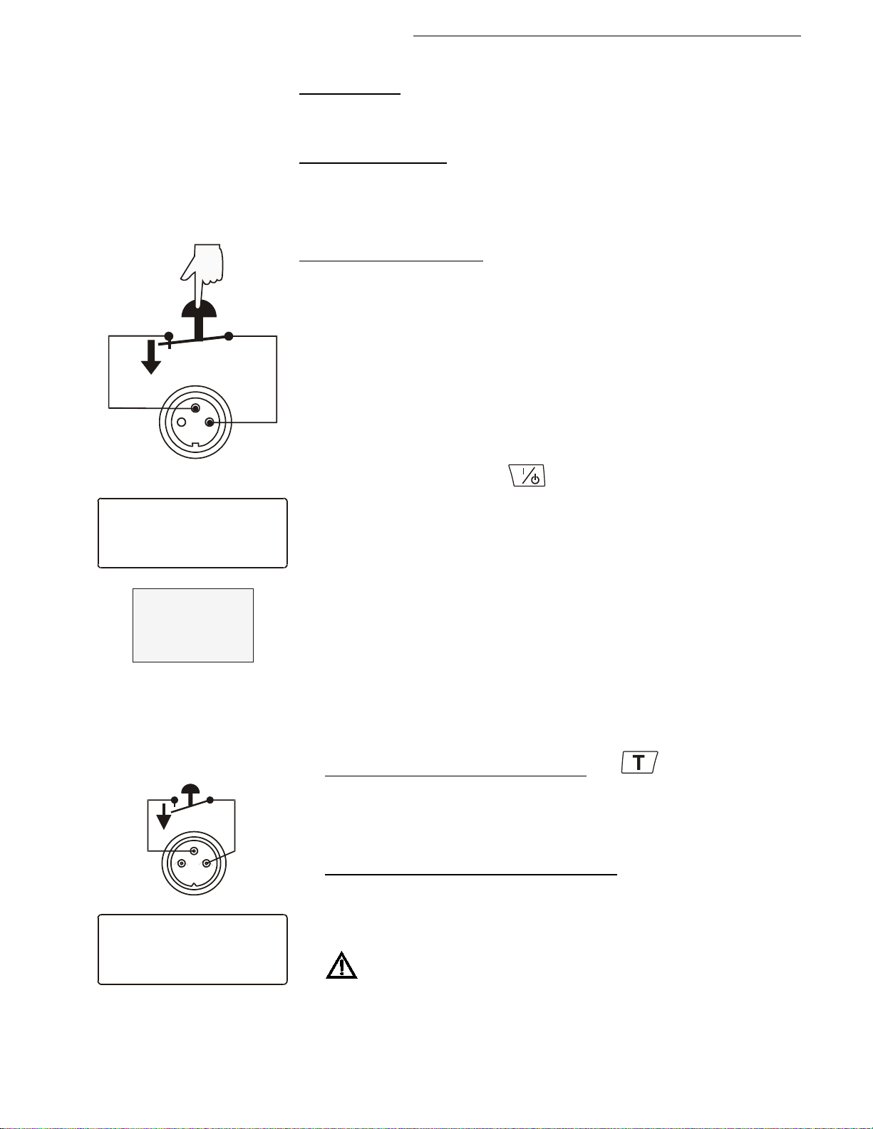
8.5.3. STAND-BY input
1
2
3
AK
Setpoint1: 150.00°C
IntAct : xxx.xx°C
Power : xx %
STAND-BY
E OFF
S xx.xx
E -----
Setpoint : xxx.xx°C
IntAct : xxx.xx°C
Profil : 4 Step:12
*** STAND-BY ***
Activate the standby input:
AK 1 2
3
Cryo-Compact Circulators
STAND-BY
Ext. StBy (10)
(for external emergency switch-off)
(Connector see page 74)
Possible parameters:
inactiv - standby input is ignored
activ - standby input is active
1. Under menu item >Ext. StBy<, set the parameter to >activ<.
2. Connect an external contact ‚AK‘ (e.g. for emergency switch-off) or an
alarm contact of the superordinated system.
In case the connection between Pin 2 and Pin 3 is interrupted by opening
the contact ‚AK‘, a complete shutdown of the circulating pump and heater
is effected, and the unit enters the condition „E OFF“.
As long as the contact remains open, line 4 of the LCD DIALOGDISPLAY flashes and displays the message „STAND-BY“.
If the contact is reclosed, the instrument returns to the standby state and
„ E OFF „ is displayed. Press to start.
Additional tips for using the STANDBY input:
The standby function can be used in conjunction with the AUTOSTART
feature (see page 39).
1. If the Autostart function is NOT turned ON, the standby input is used
as described above.
2. If the Autostart function is enabled, the instrument will revert back to
the original method of entering the setpoint (i.e. keypad, RS232,
Analog input, etc.).
• Entering the setpoint with the keypad. e.g.
As described above, a bipolar shut-down is accompanied by the
„STAND-BY“ display and the OFF state. The programmable controller
starts again when the contact is reclosed. The temperature of the
bath fluid changed during the STAND-BY state.
• Entering the s
display „STAND-BY“ appears. The setpoint value and the time are
both held at the current value. The temperature of the bath fluid will
be held constant at this temperature. The programmer continues once
the contact is reclosed.
Notice: this is not an actual shutoff feature.
etpoint with the programmer (see pages 51). The
Find Quality Products Online at: [email protected]
www.GlobalTestSupply.com
61
Page 62
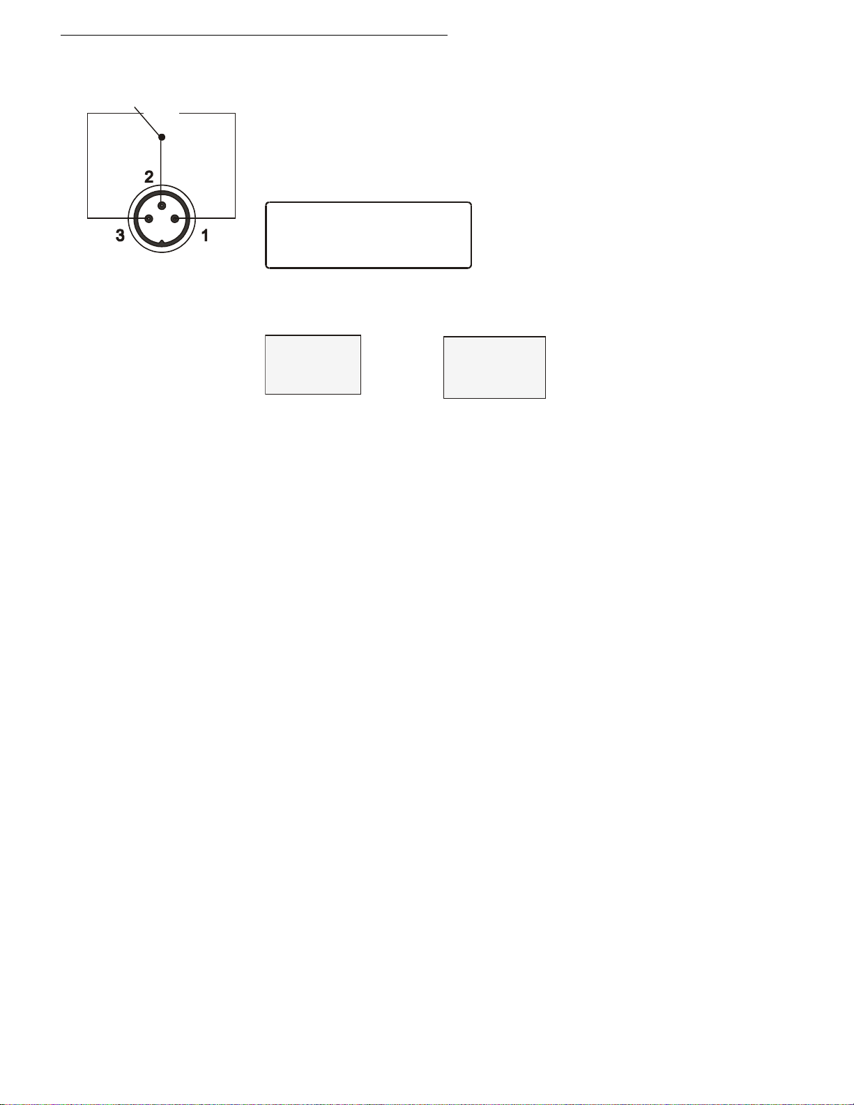
Menu functions
AlarmOut
>Function: StdBy /Alarm/Al+StBy
Type : normal /invers
-OFF-
S xx.xx
E -----
XXXXX
ALARM
CODE xx
8.5.4. ALARM output
ALARM
Alarm output (9)
(for external alarm signal)
This socket is a potential-free change-over contact. With the
adjustments in the menu >Inputs/Outputs< all operating conditions
can be signaled without having to change the pin assignments.
Menu >Inputs/Outputs<
Signification of the terms under menu item >Function< :
The Cryo-Compact Circulator is in condition
>StandBy< or >Alarm<
For >Type: normal< pins 2 and 3 are connected in any case
according to the selected >Function<.
For >Type: invers< pins 2 and 1 are connected in any case
according to the selected >Function<.
Switching capacity max. 30 W / 40 VA
Switching voltage max. 125 V∼/−
Swi
tching current max. 1 A
Find Quality Products Online at: [email protected]
62
www.GlobalTestSupply.com
Page 63
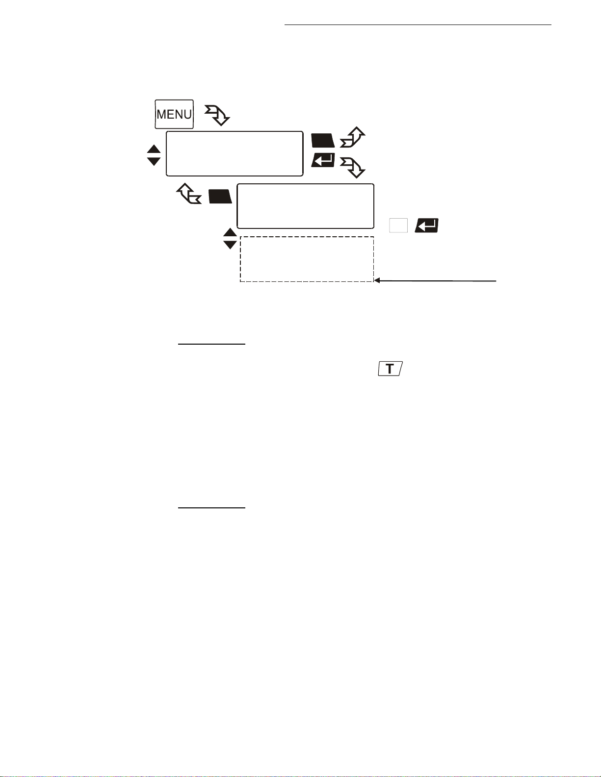
8.6. Limits
Main menu
Interface serial
ATCalibration
>Limits
ESC
ESC
1
Limits
>SetMax :300.00°C
SetMin :-94.99°C
HeatingMax: 100%
CoolingMax: 0%
IntMax :300.00°C
IntMin :-94.99°C
Upper band: 200K
Lower band: 200K
In case of external control
these menu items are
additionally indicated
CF41 0 to 100 % in steps of 1 %
Cryo-Compact Circulators
The menu >Limits< allows for setting the minimum and maximum values for all
important setting ranges and capacity variables.
SetMax: and SetMin: Maximum and minimum setpoint
Restriction for the adjustable temperature range.
Setting range: see wo
rking temperature range
The limitation of the operating temperature range effects the temperature
setting under the menu called up with the
key - Setpoint 1, 2, 3.
It is possible to adjust only working temperatures that lie within the limit range
set here.
Existing settings for Setpoint 1, 2, 3 and also for >OverTemp< and >SubTemp<
(see page 33) are automatically defered within the limit range.
HeatingMax: and CoolingMax:
Adjusted maximum heating / cooling.
Setting range: 0 t
o 100 % in steps of 1 %
Heating and cooling powers of the Cryo-Compact Circulator are adjustable.
100 % corresponds to the values in the technical specifications of the
equipment.
Factory setting: CoolingMax
CF31 100 % (fixed value)
Find Quality Products Online at: [email protected]
www.GlobalTestSupply.com
63
Page 64
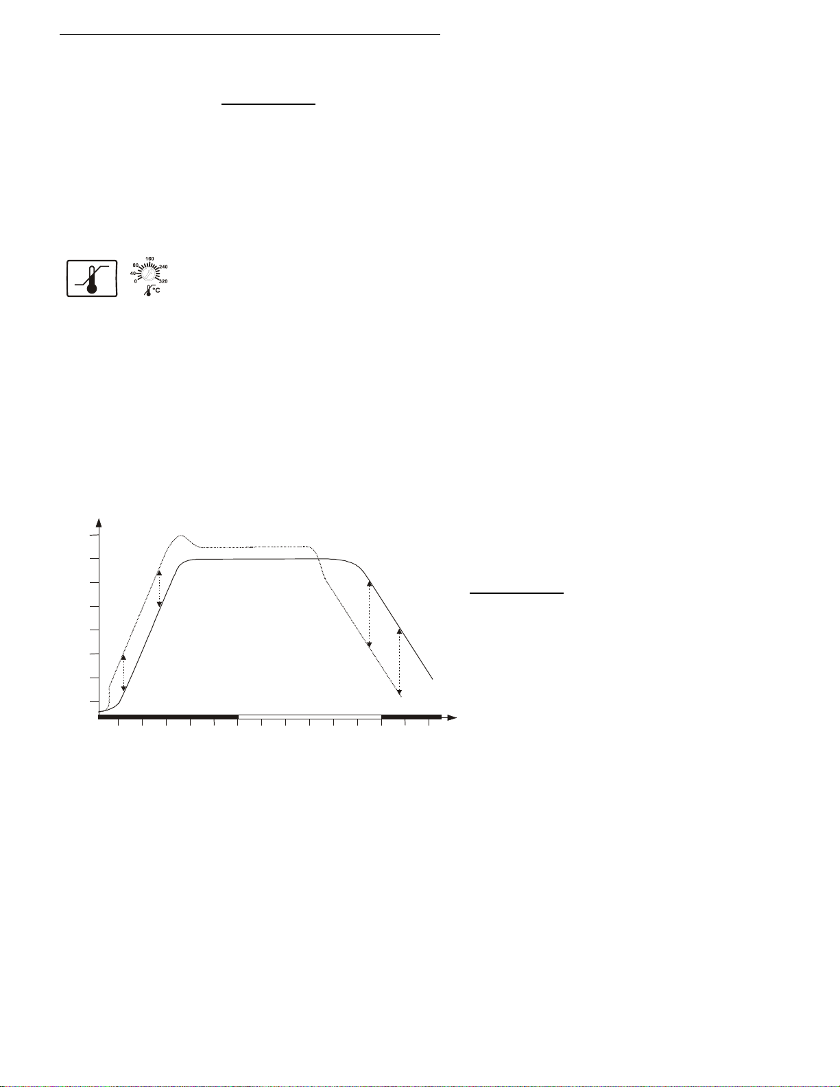
Menu functions
Upper band: and Lower band: Band limit
The band limit is active for external control.
25
50
10203040506010203040506010
[min]
75
100
150
200
°C
t
external system
internal bath
AreaUp
AreaDown
IntMax: and IntMin: L imit setting
Setting range: see working temperature range page 13
The limits IntMax and IntMin are only valid for external control. IntMax and
IntMin are used to limit the expected internal bath temperatures to any upper
and lower values. The temperature controller cannot exceed these limits even if
it would be required for reaching the temperature in the external system.
Consequently the external setpoint may thus not be reached.
Sense of a limit setting:
>SafeTemp:<
Protects the bath fluid from overheating.
Prevents an undesired alarm shut-down by the excess temperature
protection - >ALARM CODE 14<.
Set >IntMax:< to a value at least 5 °C below the >SafeTemp:< value.
Protects the pump motor from high viscosity of the bath fluid at low
temperatures.
For refrigerated Cryo-Compact Circulator s: Freezing protection when using
water as bath fluid.
For the heat-up and cool-down phases
different settings to conform to the
requirements of the particular application
are possible.
Setting range: 0 ... 200 °C
Using Upper band and Lower band, the
difference between the temperatures in
the internal bath and the external system
can be limited to any maximum value for
the heat-up or the cool-down phase.
During the heat-up phase the difference value always adds to the actual
external temperature. During the cool-down phase, the difference value is
subtracted.
Sense of a band limit:
Ensures gentle heating for the objects requiring temperature application.
Protects glass reactors, for example, from thermal shock.
Find Quality Products Online at: [email protected]
64
The IntMax: and IntMin: values are superordinated to this band limit.
www.GlobalTestSupply.com
Page 65
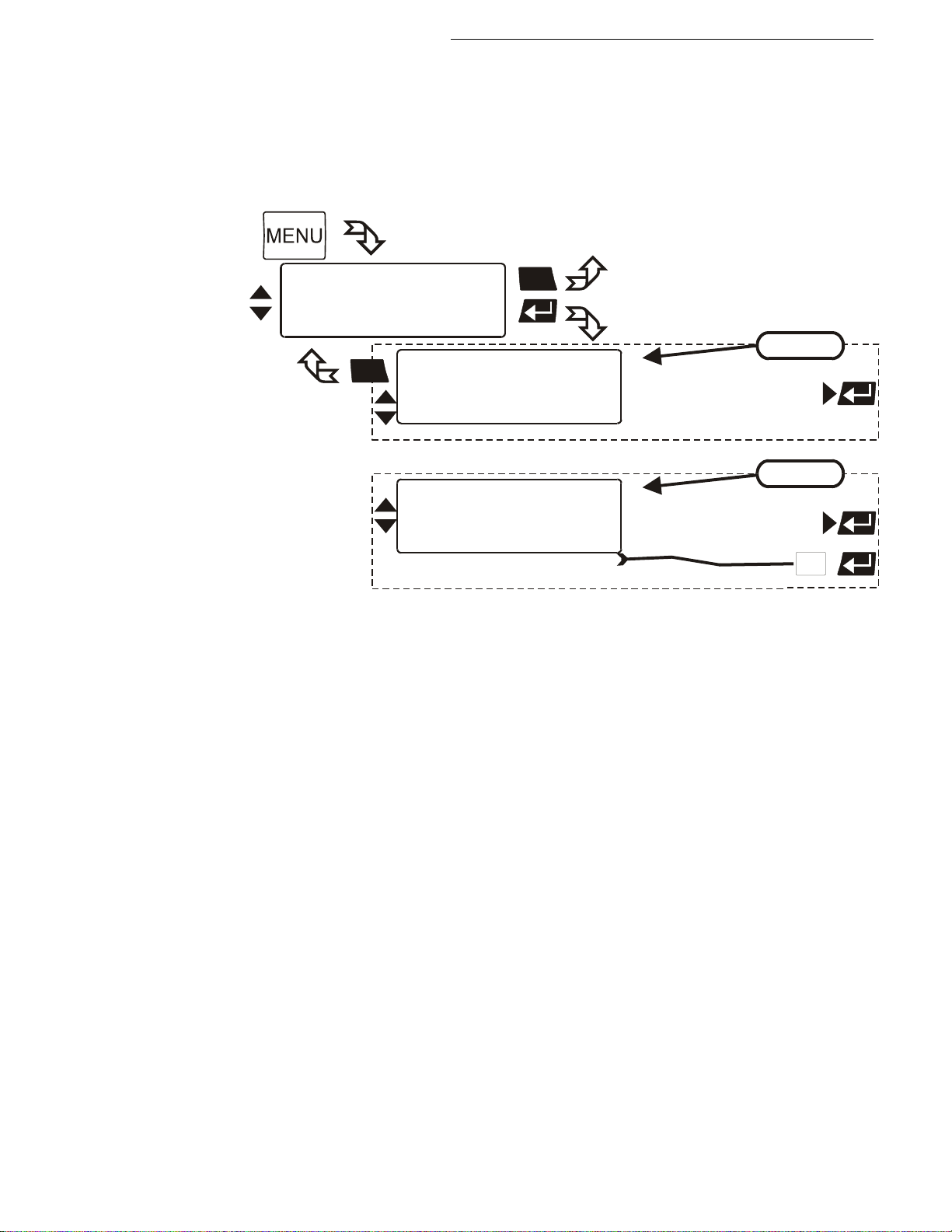
8.7. Ser ial interface
Main menu
Limits
ATCalibration
>Interface serial
ESC
Interface
>Type RS485
Baudrate 4800 /9600/19200/38400
Parity even /no/odd
Address 0
/PROFI/RS232
1
ESC
Interface
>Type RS232
Baudrate 4800 /9600/19200/38400
Parity even /no/odd
Handshake hardw / softw
/RS485/PROFI
RS232
RS485
hardware handshake
For communication between Cryo-Compact Circulator and a PC or a
superordinated process system the interface parameters of bath units must
be identical. The adjustment is usually carried out one time only in the menu
>Interface serial<.
Cryo-Compact Circulators
Type RS232 / RS485
Baud rate 4800/9600/19200/38400
Parity none/even/odd
Handshake software handshake/hardware handshake
Address 0 to 127
Factory settings:
4800 Bauds
even
Find Quality Products Online at: [email protected]
www.GlobalTestSupply.com
65
Page 66
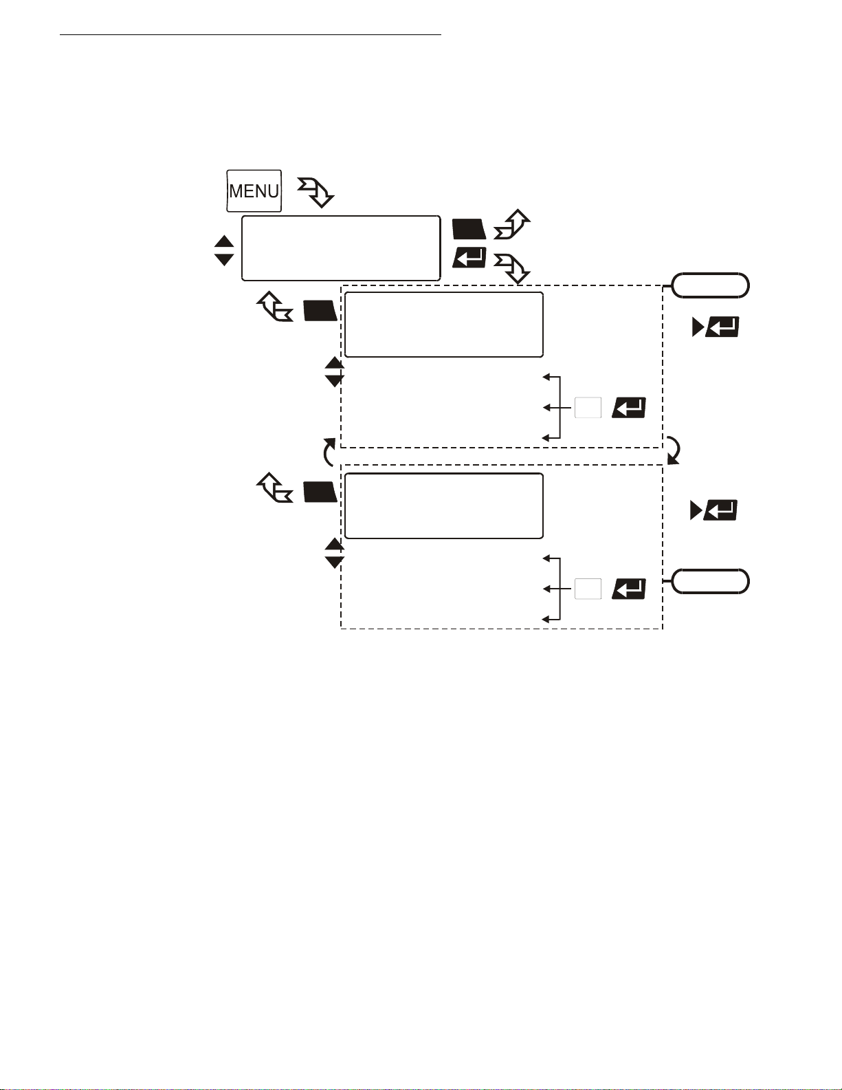
Menu functions
Main menu
Interface serial
Pump
>ATCalibration
ESC
ESC
ESC
1
1
ATCalibration
>Sensor : intern
Status : no /yes
Type : 3-point /1-point/2-point
TmpValue1: xx.xx°C
CalValue1: xx.xx°C
TmpValue2: xx.xx°C
CalValue2: xx.xx°C
TmpValue3: xx.xx°C
CalValue3: xx.xx°C
ATCalibration
>Sensor : extern
Status : no /yes
Type : 3-point /1-point/2-point
TmpValue1: xx.xx°C
CalValue1: xx.xx°C
TmpValue2: xx.xx°C
CalValue2: xx.xx°C
TmpValue3: xx.xx°C
CalValue3: xx.xx°C
internal
external
8.8. ATC Absolute Temperature Calibration, 3-point c ali bra t ion
ATC serves to compensate a temperature difference that might occur between
Cryo-Compact Circulator and a defined measuring point in the bath tank
because of physical properties.
Sensor: >intern<, >extern<
Calibration can be carried out for the internal temperature sensor and
for the external temperature sensor connected to the socket „ext.
Pt100“.
The Cryo-Compact Circulator is able to store both parameter sets.
However, only the one set under this menu item is indicated.
Status:
>no< The controller of the Cryo-Compact Circulator uses the
original curve of the temperature sensor.
Important: During the calibration process >no< needs to be set.
>yes< The controller of the Cryo-Compact Circulator uses the
new calibration curve.
Find Quality Products Online at: [email protected]
66
www.GlobalTestSupply.com
Page 67
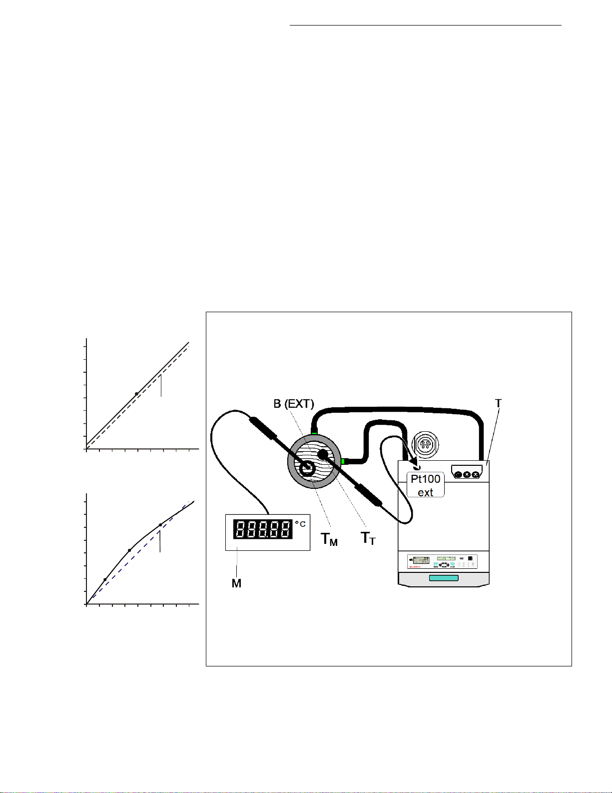
Cryo-Compact Circulators
Example:
°C°CT 1
T
°C°CT 1
T
1-point calibration
Type:
A >1-point<, >2-point < or >3-point < calibration can be carried
out.
First geometrically define the location for calibration (measuring point
), then determine the temperature values of of the calibration
T
M
points.
The calibration type also determines the number of pairs of values
indicated on the LCD DIALOG-DISPLAY.
TmpValue: 1 or 2 or 3
Defined temperature value of the calibration point. This value is
automatically stored with >CalValue< and can be indicated for control
purposes.
CalValue: 1 or 2 or 3
The „Calibration value“ is determined with a temperature measuring
device and stored under menu item >CalValue<.
Principle:
For ATC calibration, in steady state the bath temperature at the location
of the temperature sensor (T
) is determined at the respective adjusted
M
working temperature. This value is then set on the Cryo-Compact
Circulator in the menu >ATCalibration< under menu item >Calvalue X<.
This can be a 1-point, 2-point or 3-point calibration.
3-point calibration
T
1 = Original curve
T
M = Temperature measuring instrument with temperature sensor
B = Bath tank (internal or external)
T = Cryo-Compact Circulator
T
= Temperature on measuring point
M
= Temperature on Cryo-Compact Circulator
T
T
Find Quality Products Online at: [email protected]
www.GlobalTestSupply.com
67
Page 68
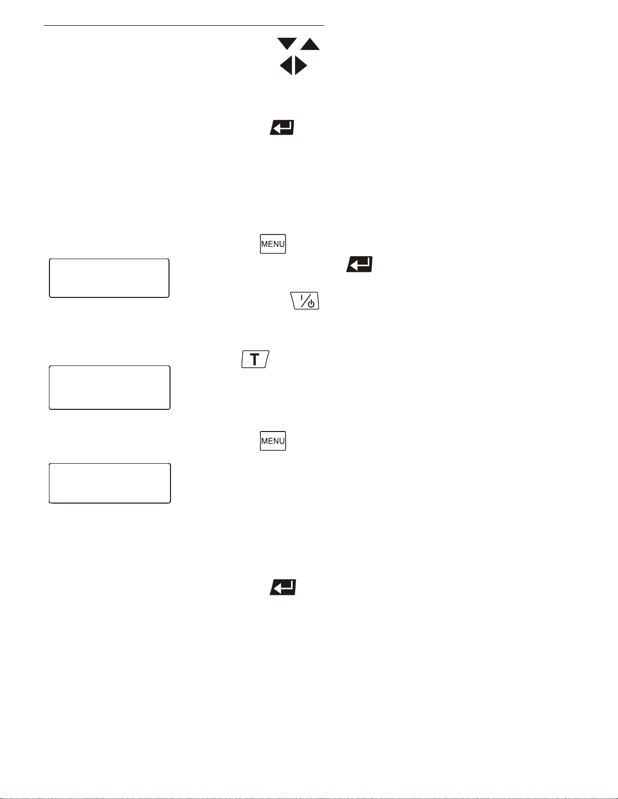
Menu functions
3. Press enter to store the new parameter or value.
Control
>ControlType: intern
Selftuning: once
Dynamic : aperio
Setpoints
>Setpoint1: 80.00°C
Setpoint2: 37.00°C
Setpoint3: 70.00°C
ATCalibration
>Sensor : intern
Status : no
Type : 3.point
TmpValue1: 80.00°C
CalValue1: 79.73°C
TmpValue2: xx.xx°C
CalValue2: xx.xx°C
TmpValue3: xx.xx°C
CalValue3: xx.xx°C
Examples:
T
= 80.00 °C
T
= 79.73 °C
T
M
T
= 120.00 °C
T
= 119.51 °C
T
M
T
= 160.00 °C
T
= 159.34 °C
T
M
1. Use the keys to select the menu item.
2. With the keys select the parameter (parameter blinks)
or
use the numeral keypad to enter the numbers (number segment
blinks).
Example:
3-point calibration for internal control.
In the temperature range of 80 °C to 160 °C the calibration curve of the
temperature sensor (T
on the measuring point (T
• Press the button. Under the menu >Control< set >ControlType<
to >intern< and press enter .
(ControlType: Can only be adjusted in the –OFF– condition)
• Press start/stop .
Calibration procedure:
1. Press and set the first temperature value under
>Setpoint1< for example (example 1
2. Wait until this temperature is maintained constant in the bath for
about 5 minutes.
3. Press the button and open the menu >ATCalibration<.
) should be assimilated to the actual temperatures
T
).
M
st
value = 80 °C).
4. Set the following:
Menu item >Sensor< to >intern< ,
Menu item >Status< to >no< ,
Menu item >Type< to >3-point<.
5. Read the value of T
on the temperature measuring device and enter
M
the value under menu item >CalValue 1< (79.73 °C) using the
numeral keypad.
Press enter and the Cryo-Compact Circulator also stores the
value of T
as value for >TmpValue 1< (80.00 °C) .
T
The first of the 3 points is now calibrated.
6. Repeat the calibration procedure for 120 °C and 160 °C.
Find Quality Products Online at: [email protected]
68
www.GlobalTestSupply.com
Page 69
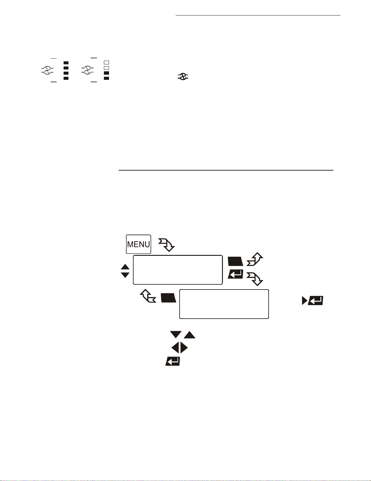
8.9. Setting the pump pressure
Main menu
Interface serial
ATCalibration
>Pump
ESC
ESC
Pump
>Pump level: 1 /2/3/4
1.
2.
3.
Cryo-Compact Circulators
Examples:
Adjusted Effective
The pressure of the circulating pump is adjustable in four grades. After
setting, the VFD-Info-Display indicates the corresponding value.
Adjustable pump capacity stage 1 ... 4
Illuminated display:
for pump pressure
Display for the adjusted pump pressure stage in the –OFF- mode.
Display for the effective pump pressure stage (rotation speed) after start.
For protecting the pump motor, the rotation speed changes with the load
applied, for example depending on the viscosity of the bath fluid at different
working temperatures.
Flow rate: 22 ... 26 l/m in
Pump capacity stage 1
Pump pressure: [bar] 0,4 0,5 0,6 0,7
Suction pump [bar] 0,2 0,26 0,33 0,4
Total capacity [bar] 0,6 0,76 0,93 1,1
in a loop circuit
2 3 4
Use the keys to select the menu item.
With the keys select the parameter (parameter blinks).
Press enter to store the new parameter or value.
Find Quality Products Online at: [email protected]
www.GlobalTestSupply.com
69
Page 70
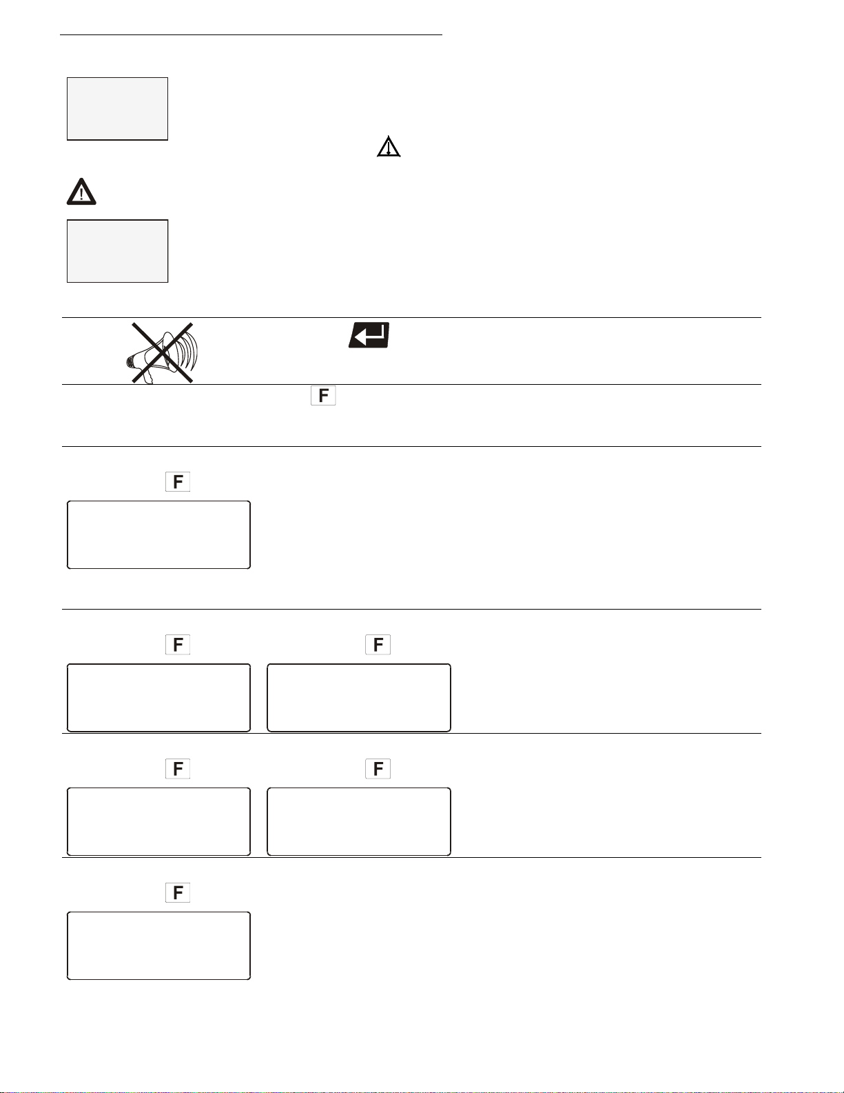
Troubleshooting guide / Error messages
XXXXX
ALARM
CODE 01
+
XXXXX
WARNING
CODE 40
ALARM
Insufficient liquid
level or float is
defective.
•
WARNING
Actual temperature
above high temperature value.
ALARM
Actual temperature
above high temperature value.
• Excess temperature warning
WARNING
Actual temperature
below low temperature value.
ALARM
Actual temperature
below low temperature value.
• Low temperature warning
ALARM
Internal working
sensor short-circuited
or interrupted.
9. Troubleshooting guide / Error messages
Alarm with a complete shutdown of the unit
er the microprocessor electronics registers a failure, a complete
“ illuminates and a continuous signal tone sounds.
Whenev
shutdown of the compressor, heater and circulating pump is performed.
The alarm light „
The VFD-COMFORT-DISPLAY indicates the cause for the alarm in form
of a code.
Warning without a complete shutdown of the unit
The VFD-COMFORT-DISPLAY indicates the cause for the warning in
form of a code and an acoustic signal sounds in regular intervals.
These messages appear every 10 seconds.
CODE 01
CODE 03
Press enter
Press
alarm messages appear.
• The Cryo-Compact Circulator is operated without bath fluid, or the
liquid level is insuffic ie nt. Replenish the bath tank with the bath fluid.
• Tube breakage has occurred (insufficient filling level due to
excessive bath fluid pumped out). Replace the tubing and replenish
the bath tank with the bath fluid.
• The float is defect (e. g., because damaged in transit). Repair by
authorized JULABO service personnel.
to indicate the help text in the LCD DIALOG-DISPLAY when
CODE 03
to quit the audible signal.
or
Excess temperature alarm
Warn-Type: Se
>Warning< or >Alarm<
t to
CODE 04
CODE 05
CODE 04
• Cable of the working temperature sensor interrupted or shortcircuited.
or
Low temperature alarm.
Warn-Type: Se
>Warning< or >Alarm<
t to
Find Quality Products Online at: [email protected]
70
www.GlobalTestSupply.com
Page 71
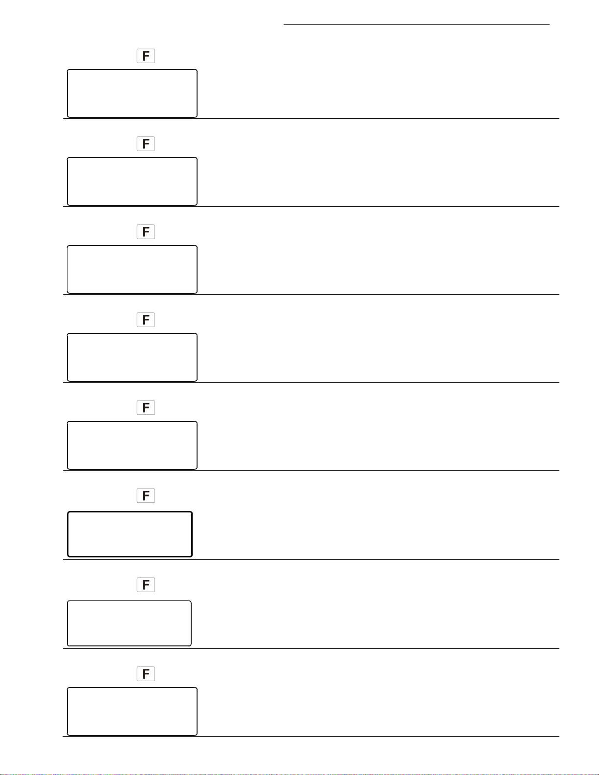
Cryo-Compact Circulators
ALARM
Difference between
working- and safetytemp. Bigger than
permissible value.
• Defect of the working or excess temperature sensor.
ALARM
The internal I2C
bus-system shows
a failure.
ALARM
Error in A/Dconverter of the
internal measuring
system.
ALARM
Working temperature
exceeds the adjusted
safety temperature.
• Excess temperature sensors defect.
ALARM
External control
selected, but ext.
sensor not connected
or defective.
• External control selected, but external Pt100 sensor not connected
WARNING
Cooling is affected
or ambient temperature
to high
Clean condenser
WARNING
Compressor does not
work. Compressor
will be automatic-
ally reconnected.
ALARM
Internal safetytemperature sensor
short-circuited or
interrupted.
CODE 06
CODE 07
CODE 12
CODE 14
Working temperature and excess temperature sensors report a
temperature difference of more than 35 K.
• Other errors (I2C-BUS errors)
• Error in A/D converter
• The excess temperature value lies below the working temperature
setpoint. Set the excess temperature to a higher value.
CODE 15
CODE 20
CODE 21
CODE 33
or defect.
• Cooling of the condenser is affected. Clean air-cooled condenser.
Check the flow rate and cooling water temperature on water-cooled
condenser.
• Compressor does not work.
After a short cooling interval, the compressor motor will be
automatically reconnected and the message "CODE 21" no longer
appears.
• Cable of the excess temperature sensor interrupted or short-circuited
Find Quality Products Online at: [email protected]
www.GlobalTestSupply.com
71
Page 72
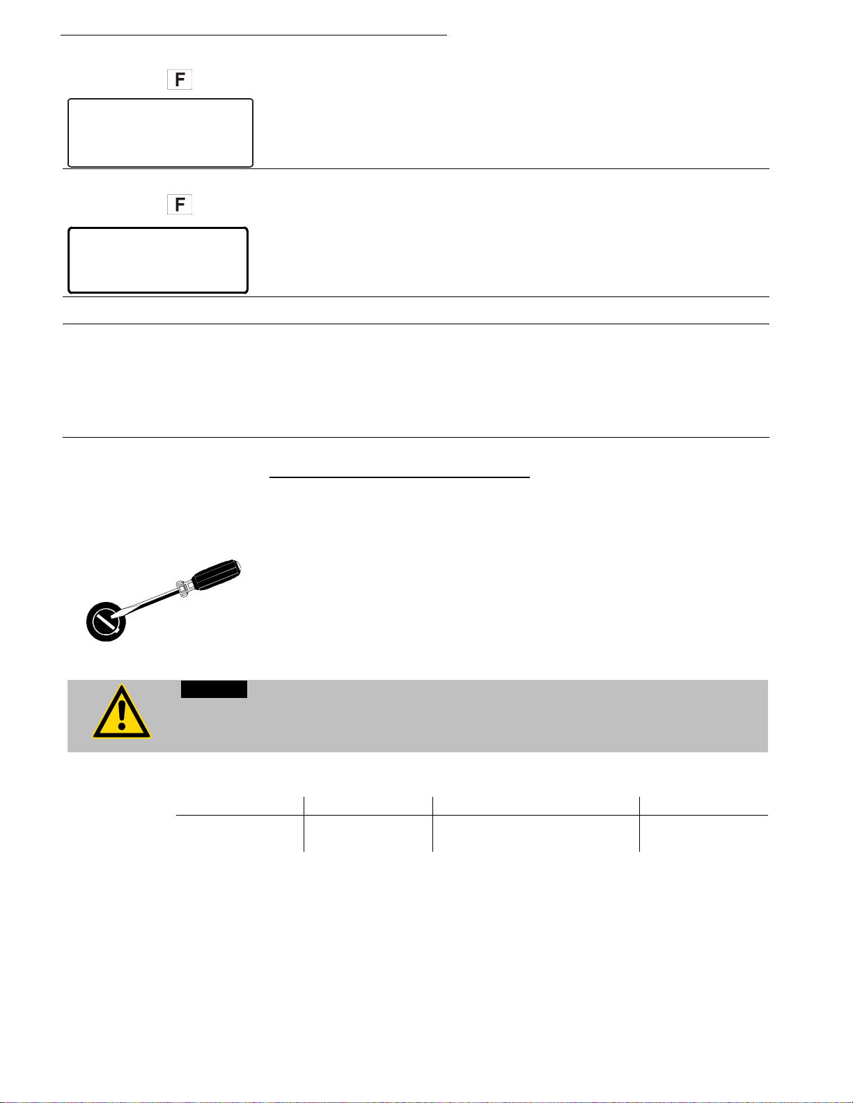
Troubleshooting guide / Error messages
ALARM
Ext. Sensor input
without signal but
setpoint programming
set to ext. Pt100.
WARNING
Niveau level warning
Critical fluid level
Replenish the bath
tank with bath fluid
• The early warning system for low level signals a critical fluid level.
T 20 A (CF41 115 V / 60 Hz)
Warning:
Only use fine fuses with a nominal value as specified.
Manufacturer
Supplier
Type
Order No.
Schurter
Schurter
G-fuse insert SPT
T16A 5x20mm
No. 0001.2516
• Ext. Pt100 sensor input without signal, but setpoint programming set
CODE 38
to external Pt100.
CODE 40
Replenish the bath tank with the bath fluid.
Cancel the alarm state.
Press the mains power switch off. After eliminating the malfunction,
press the mains power on again to cancel the alarm state.
If the unit cannot be returned to operation, contact an authorized service
station.
Disturbances that are not indicated.
The electronic pump motor is overload-protected by an electronic current
limiter. If viscosity of the bath fluid is or becomes too high, the motor
stops running.
Mains fuses:
The mains fuses on the rear of the unit may easily be exchanged as
shown on the left.
Fine fuses: – T 16 A, 250 V~ , D5 x 20 mm
Before exchanging the fuses, turn off the mains power switch and disconnect the
power plug from the mains socket!
Example:
Find Quality Products Online at: [email protected]
72
www.GlobalTestSupply.com
Page 73
10. Electrical connections
RS232/RS485 serial interface
Pin assignments RS485:
Order No.
Description
8 980 073
RS232 interface cable 9-pol./9-pol. , 2,5 m
8 900 110
USB interface adapter cable
9 6
5
1
Notice:
Use shielded cables only.
The shield of the connecting cable is electrically connected to the plug housing.
The unit ensures safe operation if connecting cables with a maximum length of 3 m are
used. The use of longer cables does not affect proper performance of the unit, however
external interferences may have a negative impact on safe operation.
This port can be used to connect a computer with an RS232 or RS485 cable
for remote control of the Cryo-Compact Circulator .
SERIAL
Pin assignments RS232:
Pin 2 RxD Receive Data
Pin 3 TxD Tr ansmit Data
Pin 5 0 V Sig n al GND
Pin 7 RTS Request to send
Pin 8 CTS Clear to send
Pin 1, 4, 6; 9 Reserved - do not use!
Cryo-Compact Circulators
Notice: RS485 serial interface
The max. load current between Pin 5 and Pin 6 is 50 mA.
Accessori
es:
Pin 3 B
Pin 5 0 V Sig n al GND
Pin 6 +5 V (50 mA max. load current)
Pin 8 A
Pins 1; 2; 7; 9 are reserved - do not use!
Find Quality Products Online at: [email protected]
www.GlobalTestSupply.com
73
Page 74
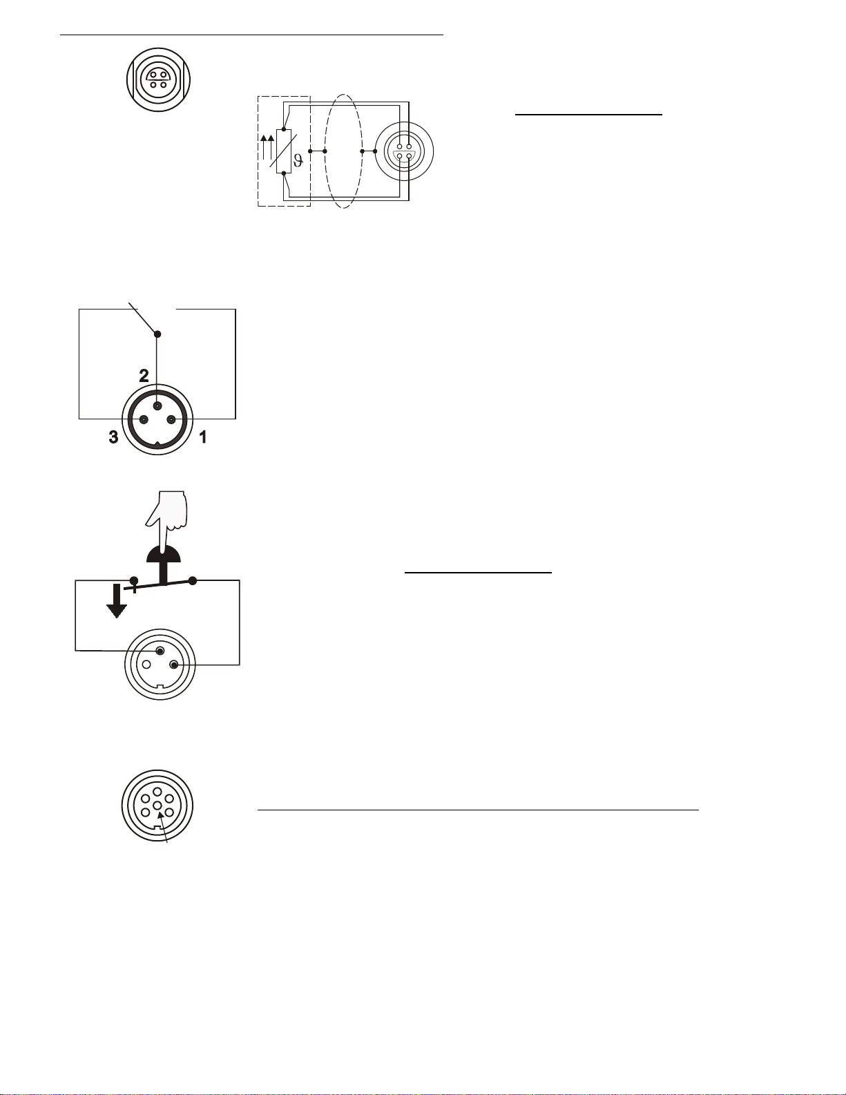
Electrical connections
Socket for external Pt100 sensor
The shield of the connecting cable is electrically connected to the plug
STAND-BY input
4
1
3
2
1
4
2
3
Shield Plug
Look on
soldering side.
Pt100
1
2
3
AK
1
2
3
4
5
6
ext. Pt100
ALARM
housing and the sensor tube.
Alarm output
(for external alarm signal)
This potential-free change-over contact is activated in case of an alarm
when pins 2 and 3 are connected.
Switching capacity max. 30 W / 40 VA
Switching voltage max. 125 V∼/−
Switching current max. 1 A
Pin assignment:
Pin Si
1 I+
2 U+
3 U 4 I-
gnal
(for external emergency switch-off)
Pin assignment: Pin S
1 not connected
2 5 V / DC
3 0 V
Functional description see page 61
STAND-BY
Programmer input / temperature recorder output
Pin Si
REG+E-PROG
Find Quality Products Online at: [email protected]
74
1 Voltage output Channel 1 0 ... 10 V
2 Voltage output Channel 2 0 ... 10 V
3 GND for outputs 0 V
4 Programmer input EPROG 0 to 10 V / 0 to 20 mA
5 Current output Channel 3 0 to 20 mA / 4 to 20 mA
6 GND for Programmer 0 V
Functional description see page 58
www.GlobalTestSupply.com
ignal
gnal
Page 75
11. Remote control
-OFF-
S xxxx
I xxxx
R
Like all parameters which can be entered through the keypad, interface
is turned off.
If the Cryo-Compact Circulator is put into remote control mode via the configuration
line feed (LF, Hex: 0A).
To ensure a safe data transfer, the time gap between two commands should be at
10 ms.
9 6
5
1
11.1. Setup for remote control
1. Check the interface parameters for both interfaces (on Cryo-Compact
Circulator and PC) and make sure they match.
SERIAL
In the menu >Interface< set the menu item >Type< to >RS232< or
>RS485<.( Serial interface see page 65)
2. In the menu >Configuration< set the menu item >Setpoint< to >RS232<
or >RS485<.
(>Configuration< see page 38)
3. Connect both units with an interface cable..
parameters are stored in memory even after the Cryo-Compact Circulator
Cryo-Compact Circulators
11.2. Communica ti on with a PC or a superord i nated data system
level, the VFD COMFORT-DISPLAY will read „R -OFF-„ = REMOTE STOP. The
Cryo-Compact Circulator is now operated via the computer.
e Cryo-Compact Circulator
In general, the computer (master) sends commands t o th
(slave). The Cryo-Compact Circulator sends data (including error messages) only
when the computer sends a query.
In remote control mode: After a power interruption the order to start and all values
which have to be adjusted must be resent from the personal computer via the
interface.
AUTOSTART is not possible.
A transfer sequence consists of:
• address (RS485 interface only)
• command
• space (⇔; Hex: 20)
• parameter (the character separating decimals in a group is the period)
• end of file (↵; Hex: 0D)
• The response (data string) after an in co
mmand is always followed by a
Important times for a command transmission:
least 250 ms.
Find Quality Products Online at: [email protected]
The Cryo-Com
string followed by a LF (Line Feed). The next command should only be sent after
pact Circulator automatically responds to an in command with a data
www.GlobalTestSupply.com
75
Page 76
Remote control
The out commands are valid only in remote control mode.
⇔
⇔
↵
↵
↵
↵
Notice: OUT-commands
OUT_MODE_01
0
Use working temperature >Setpoint1<
OUT_MODE_01
1
Use working temperature >Setpoint2<
OUT_MODE_01
2
Use working temperature >Setpoint3<
Temperature control by using the stored parameters.
Single selftuning of controlled system after the next start.
setpoint is to be reached.
The commands are divided into IN or OUT commands.
IN commands: asking for parameters to be displayed
OUT commands: setting parameters
Examples:
When the RS485 interface is used, the three-digit instrument address stands in front
of each command.
(example: address Ad32 = A032)
Command to set the working temperature >Setpoint1< to 55.5 °C
OUT_SP_00
A032_OUT_SP_00
Command to ask for the working temperature >Setpoint1<
IN_SP_00
A032_IN_SP_00
Response from the Cryo-Compact Circulator :
55.5
A032_55.5
LF
55.5↵
55.5↵
LF
Temperature values can be displayed on the Cryo-Compact Circulator in °C or °F.
The settings sent via the interface must also be made in the selected unit according
to this setting.
11.3. List of commands
OUT commands: Setting parameters or temperature values.
Command Parameter Response of Cryo-Compact Circulator
OUT_MODE_02 0 Selftuning „off“.
OUT_MODE_02 1 Selftuning „once“
OUT_MODE_02 2 Selftuning „always“
Continual selftuning of controlled system whenever a new
Find Quality Products Online at: [email protected]
76
www.GlobalTestSupply.com
Page 77

Cryo-Compact Circulators
Voltage 0 V ... 10 V
Current 0 mA ... 20 mA
OUT_MODE_04
0
Temperature control of internal bath.
OUT_MODE_04
1
External control with Pt100 sensor.
OUT_MODE_05
0
Stop the unit = R –OFF-.
OUT_MODE_05
1
Start the unit.
OUT_MODE_08
0
Set the control dynamics - aperiodic
OUT_MODE_08
1
Set the control dynamics - standard
OUT_SP_00
xxx.xx
Set working temperature. „Setpoint 1“
OUT_SP_01
xxx.xx
Set working temperature. „Setpoint 2“
OUT_SP_02
xxx.xx
Set working temperature. „Setpoint 3“
OUT_SP_03
xxx.xx
Set high temperature warning limit „OverTemp“
OUT_SP_04
xxx.xx
Set low temperature warning limit „SubTemp“
-100 ... +100 [%]
OUT_SP_07
x
Set the pump pressure stage. (1 ... 4)
OUT_PAR_06
xxx
Xp control parameter of the internal controller. 0.1 ... 99 .9
OUT_PAR_07
xxx
Tn control parameter of the internal controller. 3 ... 9999
OUT_PAR_08
xxx
Tv control parameter of the internal controller. 0 ... 999
OUT_PAR_09
xxx
Xp control parameter of the cascade controller. 0.1 ... 99.9
OUT_PAR_10
xxx
Proportional portion of the cascade controller. 1 ... 99.9
OUT_PAR_11
xxx
Tn control parameter of the cascade controller. 3 ... 9999
OUT_PAR_12
xxx
Tv control parameter of the cascade controller. 0 ... 999
OUT_PAR_13
xxx
Maximum internal temperature of the cascade controller.
OUT_PAR_14
xxx
Minimum internal temperature of the cascade controller.
OUT_PAR_15
xxx
Band limit (upper) 0 .. . 200 °C
OUT_PAR_16
xxx
Band limit (lower) 0 ... 200 °C
Command Parameter Response of Cryo-Compact Circulator
OUT_MODE_03 0 Set external programmer input to voltage.
OUT_MODE_03 1 Set external programmer input to current.
OUT_SP_06 xxx.xx Set manipulated variable for the heater via serial interface
OUT_PAR_04 x.x CoSpeed for external control 0 ... 5.0
OUT_HIL_00 -xxx Set the desired maximum cooling power (0 % to 100 %).
Note: Enter the value with a preceding negative sign!
This command only valid with the CF41.
OUT_HIL_01 xxx Set the desired maximum heating power (10 % to 100 %).
Find Quality Products Online at: [email protected]
www.GlobalTestSupply.com
77
Page 78

Remote control
VERSION
None
Number of software version (V X.xx)
STATUS
none
Status message, error message (see page 79)
IN_PV_00
none
Actual bath temperature.
IN_PV_01
none
Heating power being used (%).
IN_PV_02
none
Temperature value registered by the external Pt100 sensor.
IN_PV_03
none
Temperature value registered by the safety sensor.
protection
IN_SP_00
none
Working temperature „Setpoint 1“
IN_SP_01
none
Working temperature „Setpoint 2“
IN_SP_02
none
Working temperature „Setpoint 3“
IN_SP_03
none
High temperature warning limit „OverTemp“
IN_SP_04
none
Low temperature warning limit „SubTemp“
(REG+E-PROG) .
IN_SP_06
none
Temperature indicatio in °C or °F
after start.
IN_SP_08
none
Value of a flowrate sensor connected to the E-Prog input
IN_PAR_00
none
Temperature difference between working sensor and safety sensor
IN_PAR_01
none
Te - Time constant of the external bath.
IN_PAR_02
none
Si - Internal slope
IN_PAR_03
none
Ti - Time constant of the internal bath.
in the internal bath and external system).
Ratio of max. cooling capacity versus max. heating capacity
IN_PAR_06
none
Xp control parameter of the internal controller.
IN_PAR_07
none
Tn control parameter of the internal controller.
IN_PAR_08
none
Tv control parameter of the internal controller.
IN_PAR_09
none
Xp control parameter of the cascade controller.
IN_PAR_10
none
Proportional portion of the cascade controller.
IN_PAR_11
none
Tn control parameter of the cascade controller.
IN commands: As
Command Parameter Response of Cryo-Compact Circulator
IN_PV_04 none Setpoint temperature („SafeTemp“) of the excess temperature
king for parameters or temperature values to be displayed.
IN_SP_05 none Setpoint temperature of the external programmer
IN_SP_07 none 1. Adjust ed pump stage in the -OFF- condition.
2. Pump stage corresponding to the effective rotation speed
IN_PAR_04 none CoSpeed - Band limit (max. difference between the temperatures
IN_PAR_05 none Factor pk/ph0:
Find Quality Products Online at: [email protected]
78
www.GlobalTestSupply.com
Page 79

Cryo-Compact Circulators
IN_PAR_12
none
Tv control parameter of the cascade controller.
IN_PAR_13
none
Adjusted maximum internal temperature of the cascade controller.
IN_PAR_14
none
Adjusted minimum internal temperature of the cascade controller.
IN_PAR_15
none
Band limit (upper)
IN_PAR_16
none
Band limit (lower)
2 = Setpoint 3
2 = Selftuning „alway“
1 = Current 0 mA to 20 mA
1 = Temperature control with external Pt100 sensor.
1 = Start
1 = standard
00 MANUAL STOP
Cryo-Compact Circulator in „OFF“ state.
01 MANUAL START
Cryo-Compact Circulator in keypad control mode.
02 REMOTE STOP
Cryo-Compact Circulator in „r OFF“ state.
03 REMOTE START
Cryo-Compact Circulator in remote control mode.
Command Parameter Response of Cryo-Compact Circulator
IN_MODE_01 none Selected setpoint:
0 = Setpoint 1
1 = Setpoint 2
IN_MODE_02 none Selftuning type:
0 = Selftuning „off“
1 = Selftuning „once“
IN_MODE_03 none Type of the external programmer input:
0 = Voltage 0 V to 10 V
IN_MODE_04 none
Internal/external temperature control:
0 = Temperature control with internal sensor.
IN_MODE_05 none
Cryo-Compact Circulator in Stop/Start condition:
0 = Stop
IN_MODE_08 none
Adjusted control dynamics
0 = aperiodic
IN_HIL_00 none Max. cooling power (%).
IN_HIL_01 none Max. heating power (%).
11.4. Status messages
Status messages Description
Find Quality Products Online at: [email protected]
www.GlobalTestSupply.com
79
Page 80

Remote control
Error messages
WARNING
-05 WORKING SENSOR ALARM
temperature difference of more than 35 K.
-07 I2C-BUS ERROR
-09 COMMAND NOT ALLOWED IN
CURRENT OPERATING MODE
-10 VALUE TOO SMALL
-11 VALUE TOO LARGE
Entered value too large.
ALARM
-20 WARNING: CLEAN CONDENSOR
-21 WARNING: COMPRESSOR STAGE
1 DOES NOT WORK
PROGRAMMING ALARM
programming set to external Pt100.
-40 NIVEAU LEVEL WARNUNG
11.5. Error messages
Description
-01 LOW LEVEL ALARM
-03 EXCESS TEMPERATURE
-04 LOW TEMPERATURE WARNING
-06 SENSOR DIFFERENCE ALARM
-08 INVALID COMMAND
-12 TEMPERATURE MEASUREMENT
-13 WARNING : VALUE EXCEEDS
TEMPERATURE LIMITS
Low liquid level alarm
High temperature warning
Low temperature warning.
Working temperature sensor short-circuited or interrupted.
Sensor difference alarm.
ing temperature and safety sensors report a
Work
Internal error when reading or writing the I2C bus.
Invalid command.
Invalid command in current operating mode.
Entered value too small.
Error in A/D converter.
Value lies outside the adjusted range for the high and low
temperature warning limits. But value is stored.
-14 EXCESS TEMPERATURE
PROTECTOR ALARM
-15 EXTERNAL SENSOR ALARM
OR CHECK COOLING WATER
CIRCUIT OF REFRIGERATOR
-26 WARNING: STAND-BY PLUG IS
MISSING
-33 SAFETY SENSOR ALARM
-38 EXTERNAL SENSOR SETPOINT
Excess temperature protector alarm
External control selected, but external Pt100 sensor not
connected.
Cooling of the condenser is affected.
Clean ai
Check the flow rate and cooling water temperature on
water-cooled condenser.
Compressor stage 1 does not work.
External standby contact is open.
(see page 61and 74)
Excess temperature sensor short-circuited or interrupted.
Ext. Pt100 sensor input without signal and setpoint
Low liquid level warning in the internal reservoir.
r-cooled condenser.
Find Quality Products Online at: [email protected]
80
www.GlobalTestSupply.com
Page 81
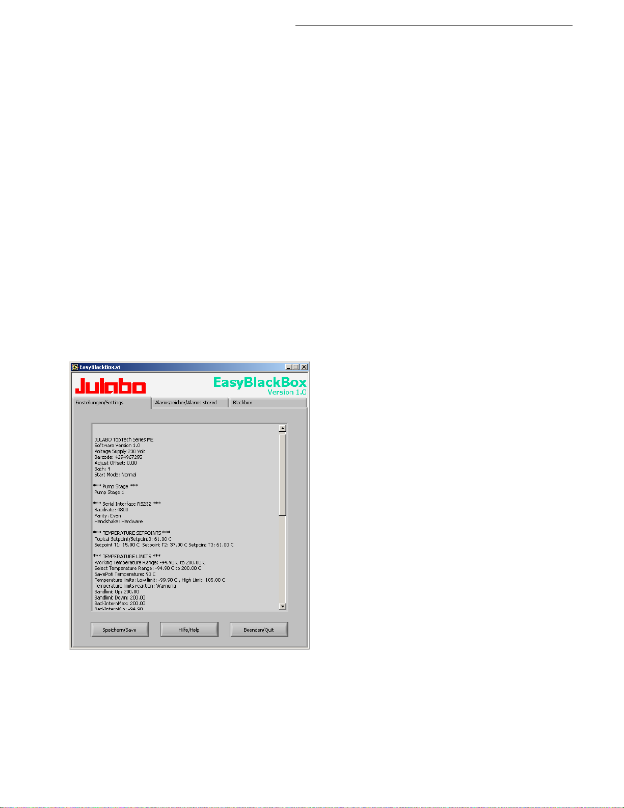
12. JULABO Service – Online remote diagnosis
used port and correct baud rate are entered.
Cryo-Compact Circulators
JULABO Cryo-Compact Circulator s of the HighTech series are
equipped with a so-called black box. This box is implemented in
the controller and records all significant data for the last 30
minutes.
In case of a failure, this data can be read out from the unit by
using special software. The respective program is available for
free download from
• Installation is easy and carried out step by step.
Please observe the instructions.
• Data read-out is possible in the conditions
„OFF“, „R OFF“ or „A L ARM“.
• Connect the Cryo-Compact Circulator to the computer using
an interface cable.
• Start the EasyBlackBox program.
The prog
rate of the unit.
You do not have this information on hand? Simply try it out!
The program keeps on sending this request until the actually
ram asks for the used port (COM1, ......) and the baud
• Data is read out and shown on the monitor
divided in the sections
>Einstellungen/Settings<,
>Alarmspeicher/Alarms stored<,
>Blackbox<
see example
• After pressing >Speichern/Save< a text file is
compiled. The program proposes a filename >C:\model description and barcode no.<.
Modifications are possible.
Find Quality Products Online at: [email protected]
www.GlobalTestSupply.com
81
Page 82
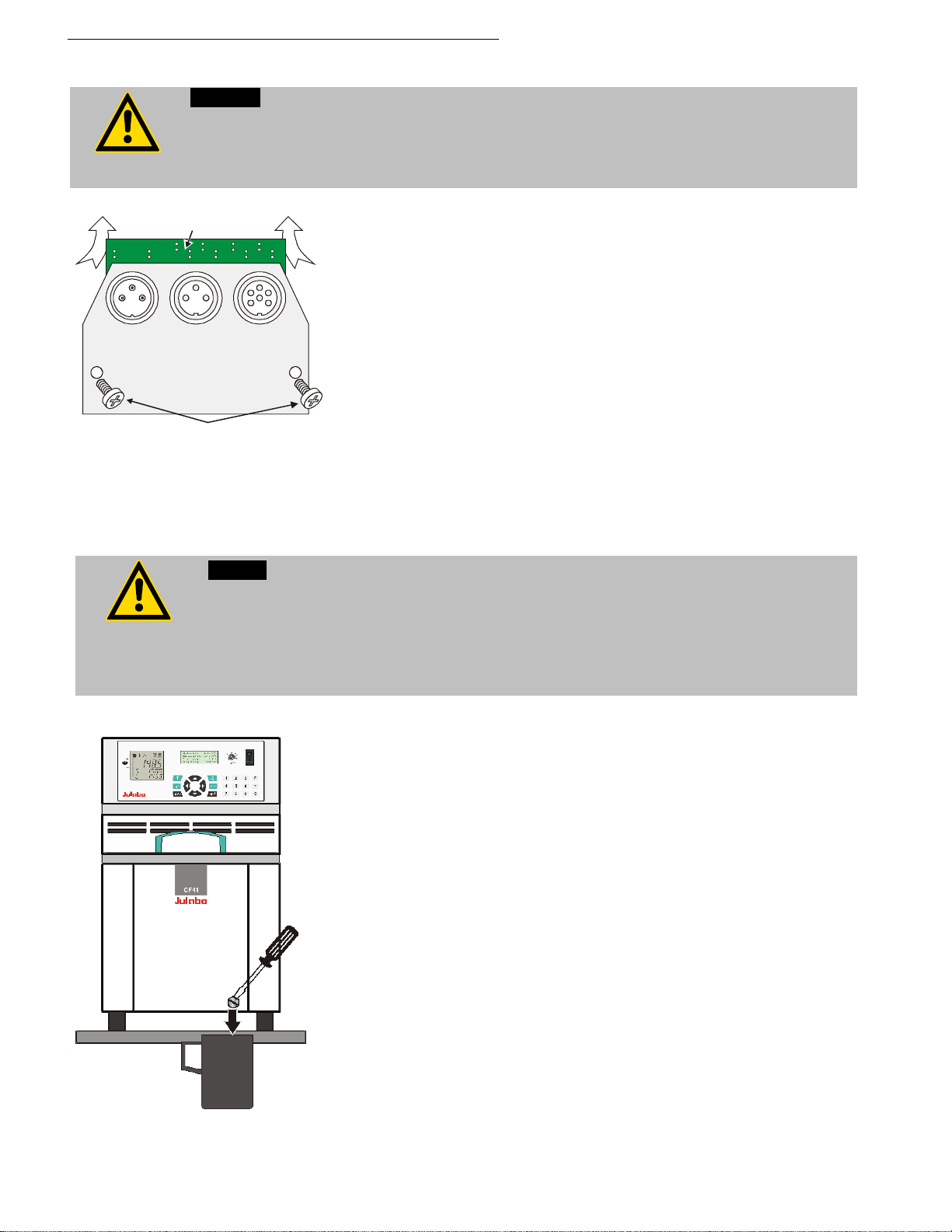
Installation of electronic module
Caution:
may only be carried out by qualified personnel.
ALARM
REG+
E-PROG
STAND-BY
A
B
protection.
13. Installation of electronic module
Always turn off the unit and disconnect the mains cable from the power source before
performing any service or maintenance procedures, or before moving the unit.
Configuration, installation, maintenance and repairs on the Cryo-Compact Circulator
• Turn off the unit with the mains switch and disconnect the
power plug.
• Open the screws (A) and remove the dummy plate.
• Carefully insert the upper edge (B) into the rear panel from
below, align the electronic module at top and bottom and
applying light pressure connect the 15-pole connector.
• Attach the electronic module using the screws (A).
• The Cryo-Compact Circulator is ready for use. It automatically
recognizes the installed electronic module.
13.1. Draining
Notice:
Do not drain the bath fluid while it is hot!
Check the temperature of the bath fluid prior to draining (by switching the unit on for
a short moment, for example).
Store and dispose the used bath fluid according to the laws for environmental
Draining
• Turn off the unit and disconnect the mains cable from the
power source.
• Place the Cryo-Compact Circulator near the rim of the table.
Use a suitabel vessel as recipient for the bath liquid
• Unscrew the drain tap and empty the unit completely.
• Tighten the drain tap.
Find Quality Products Online at: [email protected]
82
www.GlobalTestSupply.com
Page 83
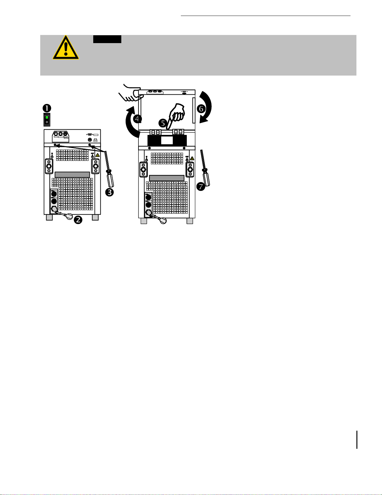
14. Cleaning / repairing the unit
Caution:
Service and repair work may be performed only by authorized electricians.
T16A
T16A
ext
Pt100
SERIAL
ALARM
REG+
E-PROG
STAND-BY
OFF
AUS
T16A
T16A
C
Always turn off the unit and disconnect the mains cable from the power source before
cleaning the unit.
Prevent humidity from entering into the circulator.
Cryo-Compact Circulators
To maintain the full cooling performance,
clean the condenser (C) from time to time.
1. Switch off device by pressing the main
power switch and
2. disconnect mains cable from power
source.
3. Remove 2 screws
4. Lift cover upwards.
5. Remove dirt at condenser by suction
cleaning.
6. Close cover and
7. Fix by means of screws.
8. Unit is ready for operation.
Cleaning:
Clean the outside of the unit using a wet cloth and low surface tension water.
The Cryo-Compact Circulator is designed for continuous operation under normal
conditions. Periodic maintenance is not required.
The tank should be filled only with a bath fluid recommended by JULABO. To avoid
contamination, it is essential to change the bath fluid from time to time.
Repairs:
Before asking for a service technician or returning a JULABO instrument for repair,
please contact an authorized JULABO service station.
Find Quality Products Online at: [email protected]
www.GlobalTestSupply.com
83
 Loading...