

JUKI Union Special MFC-7406, Union Special MFC-7407, Union Special MFC-7602, Union Special MFC-7605 Instruction Manual
Page 1
2-3
Finest Quality
Needle
Cylinder
Bed
LIUKI
Coverseam
Machine
MFC-7000A
INSTRUCTION MANUAL
Series
NOTE: Read
before
Retain
REV.10/31/01
safety
using
this
instructions
your
MFC-7000.
Instruction
carefully
Manual
for
and
understand
future
them
reference.
OP0113
Page 2
PREFACE:
This
operator's
This
manual explains in detail
adjustments
manual has been prepared
and reference letters are used
the
proper
to
guide
settings
to
point
you
for
operation
out
while
operating
specific
of
the
items
the
MFC-7000 Series machines.
machine.
discussed.
Illustrations
are used
to
show
the
Careful attention
maintain
Adjustments
performed
This
incorporate a slight
On
machine.
the
manual has been
the
following
to
superior
and cautions are presented in
out
of
sequence may have an adverse
pages
CONTENTS
PREFACE:
SAFETY
................................................................................................................................................................. 2
RULES
.......................................................................................................................................................... 3
SPECIFICATIONS:
MOTOR
TABLING
CAUTION
OPERATOR'S
ROTATION:
OPERATING
OPERATING
OPERATING
LUBRICATION:
LUBRICATION
INSERTING
THREADING
THREADING
DIFFERENTIAL
ADJUSTING
PRESSER
ROLLER
PULLER
PULLER
ADJUSTMENT
ADJUSTMENT
ADJUSTMENT
ADJUSTMENT
ADJUSTMENT
ADJUSTING
ADJUSTMENT
MAINTENANCE:
PULLEY
AND V BELT:
INSTALLATION:
AREAS:
DAILY
.............................................................................................................................................................. 7
CAUTIONS:
CAUTIONS
THE
PEDALS:
......................................................................................................................................................... 9
(CONT.):
NEEDLES:
THE
MACHINE:
THE
MACHINE
FEED
THE
STITCH
FOOT
PRESSURE
PRESSURE
LIFTER
STIITCH
LEVER:
LENGTH:
OF
OF
OF
OF
OF
TAKE-UP
OF
....................................................................................................................................................
the
instructions
performance and reliability
comprised
modification
will
be
found
and
cautions
sequence
on
the
basis
of
configuration
illustrations
designed
effect
of
available
in
and
for
operating and
and
so
that
a logical
on
the
information.
illustrations
terminology
built
into
progression
function
or
cautions.
used
adjusting
every
of
the
other
Changes
in
describing
these
machines
Union
Special machine.
is
accomplished.
related parts.
in
design
operating
and/or
will
enable you
Some
adjustments
improvements
instructions
for
may
your
.................................................................................................................................................... 4
.................................................................................................................................. 4
................................... .-..................................................................................................... 5
................................................................................................................................................... 6
CHECK
UST:
.................................................................•........................................................... 7
......................................................................................................................................... 7
(CONT.): .......................................................................................................................... 8
......................................................................................................................................... 8
........................................................................................................................................
.............................................................................................................................................
.................................................................................................................................
(CONT.): ...................................................................................................................
MECHANISM:
LENGTH:
AND
ADJUSTING
........................................................................................................................
.........................................................................................................................
LIFTER:
KNOB:
.................................................................................................................
.................................................................................................................
............................................................................................................................................
.......................................................................................................................................
LOOPER
NEEDLE
LOOPER
NEEDLE
SPREADER:
GAUGE:
BAR
AND
GUARD:
......................................................................................................................
HEIGHT:
NEEDLE:
................................................................................................................
.............................................................................................................
.......................................................................................................................
................................................................................................................................
CAM: ..................................................................................................................................
THREAD
GUIDE:
........................................................................................................................
10
11
12
13
14
14
15
15
16
17
18
18
19
19
20
21
22
23
to
2
Page 3
l.
Before
of
each
putting
machine
the
machines
is
only
described
permitted
after
in this
taking
SAFETY
manual
notice
RU
into
of
LES
service,
the
instructions
carefully
and
read
by
the
instructions. The starting
qualified
operators.
IMPORTANT!
2.
Observe
3.
The sewing
been
ascertained
the
EC
Council
Each
machine
described
the
description,
4.
All safety
of
the
machine
5.
Wear
safety glasses.
6.
In
case
of
and
changes
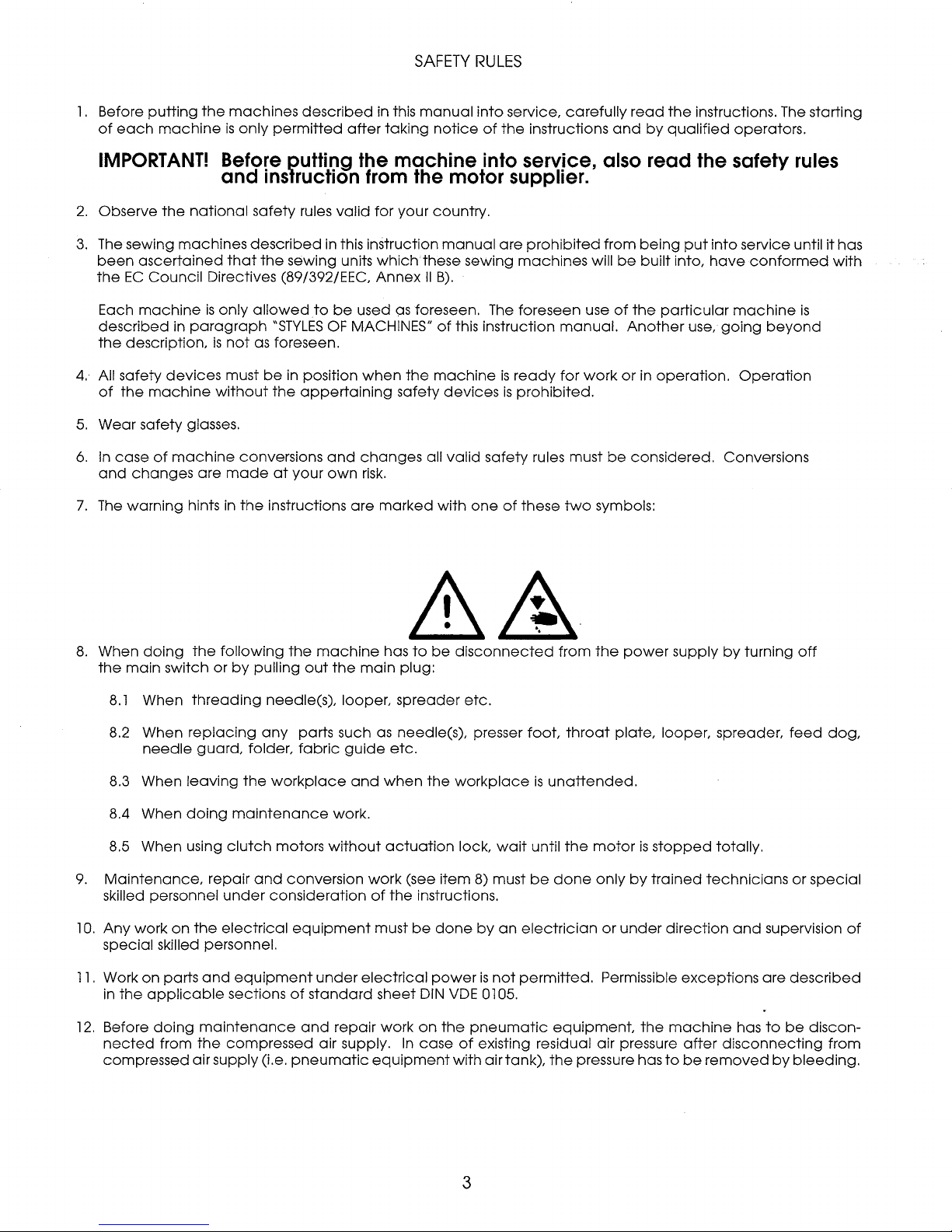
7.
The
warning
Before putting the
and
inslruction from the motor supplier.
the
national
machines
in
paragraph
devices
machine
are
hints
safety rules
described
that
the
Directives (89/392/EEC,
is
only
allowed
is
not
as foreseen.
must
be
without
conversions
made
in
the
instructions
in this instruction
sewing units
to
"STYLES
the
at
OF
in
position
appertaining
and
your
own
valid
for
which
Annex
be
used
MACHINES"
when
changes
risk.
are
marked
machine
your
country.
these sewing
II
as
foreseen. The foreseen use
the
machine
safety
all
into service, also read the safety rules
manual
B).
of
devices
valid
with
are
prohibited
machines
this instruction
is
ready
is
prohibited.
safety
one
rules must
of
these
manual.
for
two
from
will
be
of
work
or
be
symbols:
being
put
built
into,
the
particular
Another
in
considered.
use,
operation.
into
service until
have
conformed
machine
going
beyond
Operation
Conversions
is
it
has
with
8.
When
doing
the
main
8.1
When
8.2 When
needle
8.3 When
8.4 When
8.5 When using
9.
Maintenance,
skilled personnel
l
0.
Any
work
special skilled personnel.
11.
Work
on
in
the
12.
Before
nected
compressed
the
switch or
threading
replacing
guard,
leaving
doing
repair
on
the
parts
and
applicable
doing
maintenance
from
the
air supply (i.e.
following
by
maintenance
clutch
under
electrical
equipment
sections
compressed
the
pulling
needle(s), looper,
any
folder,
the
workplace
motors
and
conversion
consideration
equipment
of
pneumatic
machine
out
the
parts such as needle(s), presser
fabric
work.
without
under
standard
and
repair
air supply.
has
main
guide
and
when
actuation
work
of
must
electrical
sheet
work
equipment
to
be
plug:
spreader
etc.
the
(see
the
instructions.
be
done
power
DIN
on
In
case
disconnected
etc.
workplace
lock,
wait
item
8) must
by
an
is
not
VDE
0105.
the
pneumatic
of
existing residual air pressure
with
air tank),
from
foot,
throat
is
unattended.
until
the
be
done
electrician
permitted.
equipment
the
pressure has
the
power
plate,
motor
is
only
by
trained
or
under
Permissible
the
supply
looper, spreader,
stopped
direction
machine
to
by
turning
totally.
technicians
and
exceptions
has
after
disconnecting
be
removed
off
feed
or
special
supervision
are
described
to
be
discon-
by
bleeding.
dog,
of
from
3
Page 4
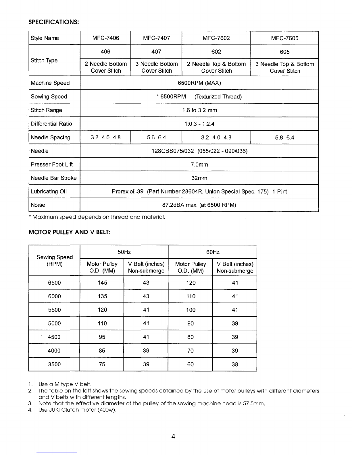
SPECIFICATIONS:
Style Name MFC-7406 MFC-7407 MFC-7602
406 407
Type
Stitch
Machine Speed 6500RPM (MAX)
Sewing Speed * 6500RPM
Stitch Range 1.6 to 3.2 mm
Differential Ratio
Needle Spacing 3.2 4.0 4.8 5.6 6.4 3.2 4.0 4.8
Needle 128GBS075/032 (055/022 - 090/036)
Presser Foot Lift
Needle Bar Stroke
Lubricating Oil Prorex oil 39 (Part Number 28604R, Union Special Spec. 175)
2 Needle Bottom 3 Needle Bottom
Cover Stitch Cover Stitch
2 Needle
1 :0.3 - 1 :2.4
7.0mm
32mm
602
Top
& Bottom
Cover Stitch
(Texturized Thread)
3 Needle
MFC-7605
605
Top
& Bottom
Cover Stitch
5.6 6.4
1 Pint
Noise 87.2dBA max. (at 6500 RPM)
* Maximum speed
MOTOR
PULLEY
Sewing Speed
(RPM) Motor Pulley V Belt (inches)
6500
6000 135
5500 120
5000
4500
depends
AND V
O.D. (MM)
on
thread
and
material.
BELT:
50Hz 60Hz
Non-submerge
145 43
43
41
110
95
41
41
Motor Pulley
O.D. (MM)
120
110
100
90 39
80 39
V Belt (inches)
Non-submerge
4000 85 39 70 39
3500
75
39
60 38
41
41
41
1 .
Use
a M
type
V belt.
2.
The
table
on
the
left
shows
the
3.
4.
and
V belts with different lengths.
Note
that
the
effective
Use
JUKI
Clutch
motor
(400w).
sewing speeds
diameter
of
the
pulley
obtained
of
the
sewing
by
the
use
of
machine
motor
head
4
pulleys with
is
57.5mm.
different
diameters
Page 5
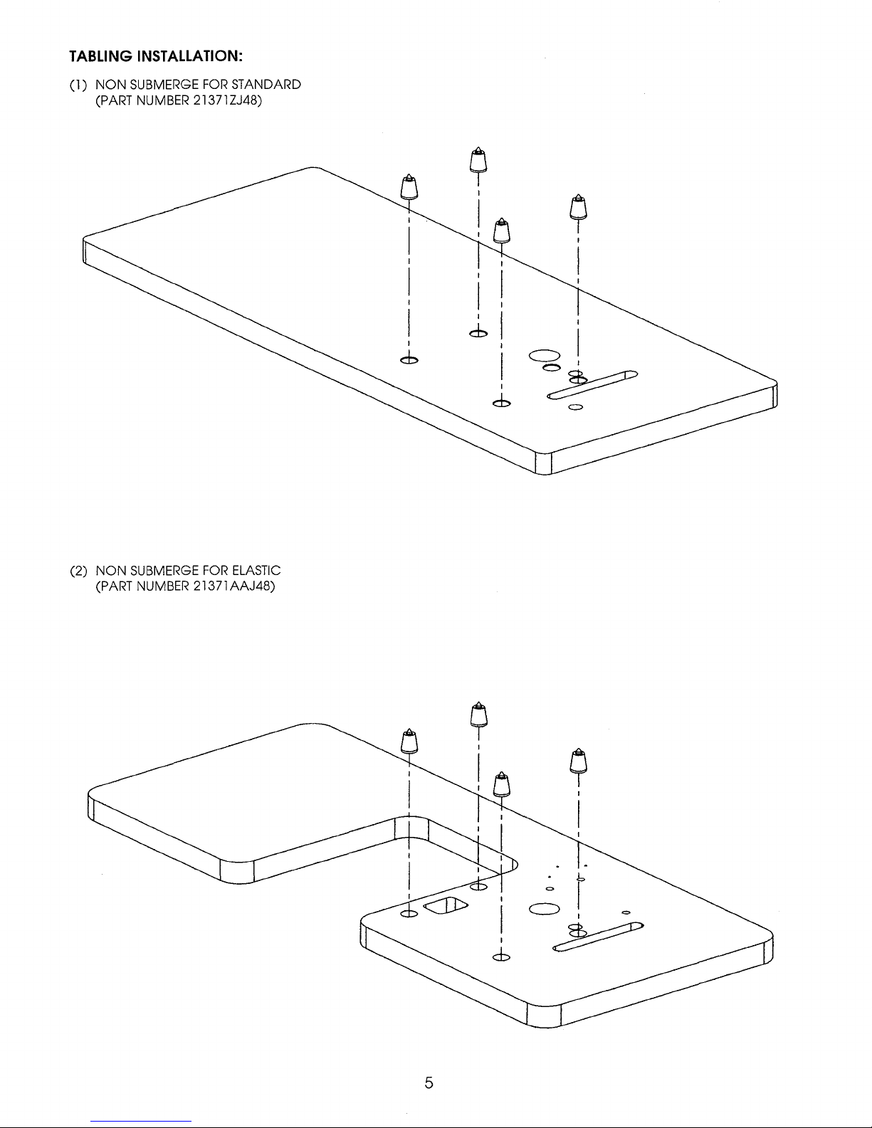
TABLING
(l)
INSTALLATION:
NON
SUBMERGE
(PART NUMBER 21371ZJ48)
FOR
STANDARD
9
I
I
I
(2)
NON
SUBMERGE
(PART NUMBER 21371AAJ48)
FOR
ELASTIC
C)
I
~
=
9
I
I
5
Page 6
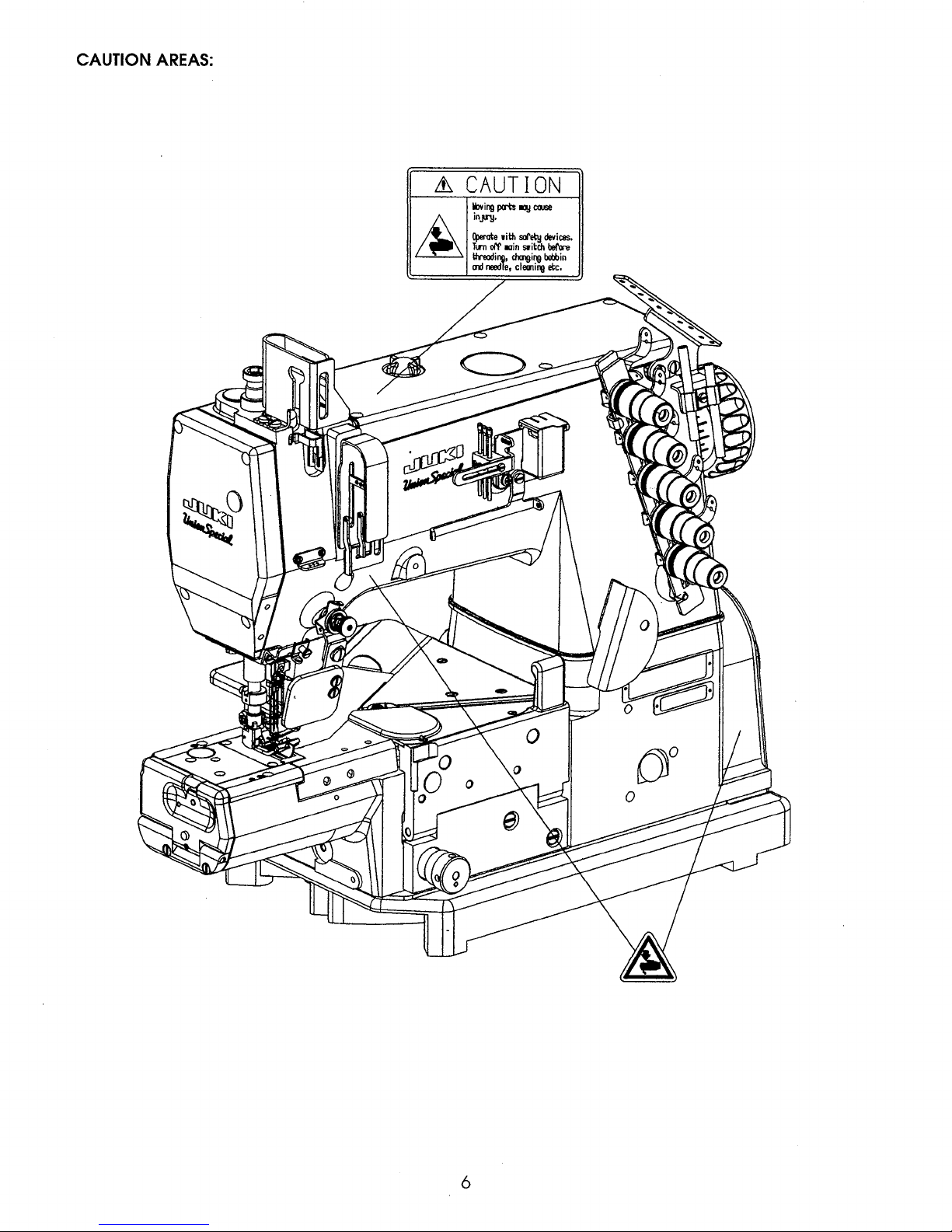
CAUTION
AREAS:
~
CAUTION
6
Page 7
OPERATOR'S
The
following should
•Oil
flow
•Oil
level
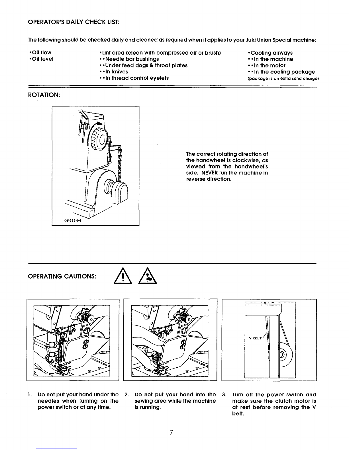
ROTATION:
DAILY CHECK
be
checked
• Lint
• •
• • Under
• •In knives
••In
LIST:
daily
area
Needle
thread
and
cleaned
(clean
bar
bushings • • In
feed
dogs & throat
as required when it applies
with compressed
air
plates
or
to
brush)
control eyelets
The
correct
the
handwheel
viewed
side.
from
NEVER
rotating
is
the
run
reverse direction.
your Juki Union Special machine:
•
Cooling
• • In
• • In
(package
direction
clockwise,
the
the
the
is
of
as
airways
machine
motor
cooling
an
extra
package
send
charge)
handwheel's
the
machine
in
OPERATING
OP026-94
CAUTIONS:
V
BELT
1.
Do
not
put
your
hand
needles
power
switch or
under the
when turning on
at
any
time.
the
2.
Do
not
sewing
is
running.
put
area
your
while
hand
the
into the
machine
3.
Turn
make
at
belt.
7
off
rest
the
sure
before
power
the
clutch
removing
switch
motor
and
the
is
V
Page 8
OPERATING CAUTIONS
4.
During operation,
5.
Do not
been
6.
Before inspecting, adjusting,
Make
switch.
7.
Turn
8.
Do
operate
provided. Doing so
sure the flywheel on
DO
NOT
OFF
the
not
wipe
your
depress
power
the
machine
do
machine
switch
(CONT.):
not
allow
is
very
the
the
foot
when
surface with
head,
without
the
dangerous.
cleaning,
motor
has stopped, it will
pedal
you
leave
hands or
proper
threading
while
the
your
lacquer
any
instrument, tool
belt
guard, sewing guards or
the
head
or
replacing
be
kept
running
motor
is
running
machine
or
in
or
case
thinner.
etc.
near
needles, turn
by
it will
cause
of a power
handwheel, V belt
any
other protectors
OFF
the
inertia after turning
the
machine
to
failure.
and
motor.
that
have
power
OFF
the
switch.
power
rotate abruptly.
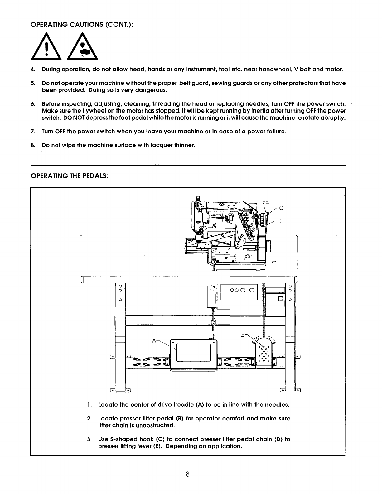
OPERATING
THE
PEDALS:
C
D
0
0
0
A
00
0 0 I
IUl!lr---
•--,1 :
1.
Locate
2.
Locate presser lifter
lifter
3.
Use
presser lifting lever
the
center
chain
is
S-shaped
of
drive
pedal
unobstructed.
hook
(C)
to
(E).
Depending
treadle
(B)
for
connect
(A)
to
be
in
operator
comfort
presser lifter
on
application.
line
with
and
pedal
the
chain
8
needles.
make
(D)
sure
to
Page 9

LUBRICATION:
The
oil should
1.
If oil
is
2.
Fill
between
&
3.
To
drain
4.
To
ensure oil flow through
be
between
required
lines
CAUTION:
oil reservoir,
the
two
remove
oil
cap
(B)
with Union Special
Do
not
exceed
leakage
remove
machine,
D
red lines in sight
(A).
Specification
the
upper
and
possible overheating.
oil
drain
cap
(C) on
check
oil flow
gauge
red
C
UPPER LEVEL
LINE
LOWER
LINE
175 oil (Union Special Part No. 28604R).
marker
the
underside
window
LEVEL
(B)
when
the
line. Excessive
of
(D).
machine
the
machine.
0
oil
in
is
at
the
rest.
0
machine
will result in oil
9
Page 10

LUBRICATION (CONT.):
A
Lubrication
*(Optional,
1.
Open
2.
The
back
3.
If
adjustment
4.
Saturate
of
extra
cloth
of
silicone
Needle
send
plate
the
needles
is
necessary
Tip
charge
and
oil
into
Dipper
item)
well
cover
should
loosen
felt
(C)
(A), fill
just
screw
if
the
well
touch
the
(D)
machine
(B)
approximately
front
and
move
is
started
of
felt
(C).
dipper
immediately
80%
as
required.
full
after
with
silicone
lubricating
oil.
needle
tip
dipper.
lO
Page 11

INSERTING
The
standard
Insert
needles
1.
Bring
needle
NEEDLES:
needle
according
is
head
A
128GBS,
to
the
(A)
to
the
needle
following
highest
range
sizes"
procedure:
position.
055/022 -090/036."
2.
3.
Loosen
the
Retighten
screws
operator's
(B),
side.
screws
insert
(B).
needles
into
holes.
The
needle
scarf
should
face
rearwards
as
viewed
from
11
Page 12

THREADING
Turn
the
.
&
Thread
NOTE:
the
machine
When
THE
MACHINE:
off
main
motor
has
according
threading
power
switch
completely
two
needle
before
stopped
to
the following
machines
threading! When using
.
threading
use needles "A" & "C".
illustrations.
clutch
motors
without
actuation
lock
wait
until
A Left
B
C Right
D
E Looper Thread
NOTE:
Needle
Middle
Spreader
Needle
Needle
When
Thread
Thread
Thread
Thread
threading
two
(D
Thread Lubricator
Needle
®
@
Needle
@ Thread Nipper,
@
Thread Take-Up
needle
machines
Area
Thread Eyelet
Bar
Area
use needles "A" & "C", DO
Area
Spreader
Area
Area
NOT
use
12
needle
"B".
Page 13

THREADING
THE
MACHINE (CONT.):
A
When
1.
Saturate
2.
Pass
When
1.
Remove
the
thread
the
needle
felt
needle
felt
thread
(A).
over
thread
(A).
lubricator
felt.
lubricator
is used:
is
not
used:
Twisted Thread
Non-Twist Thread
When using
as
wooly
thread,
immediate
do
CAUTION!
an
untwisted thread such
nylon
thread
not
wind
it
thread guide.
or
around the
weak
13
Page 14

ADJUSTING
1.
Locking
EN9424.
2.
To
change
and
rotate
THE
STITCH
Turn
length!
lock
feature
stitch
handwheel
off
main
When
wait
may
length
LENGTH:
power
using
until
the
be
engaged,
push
in
appropriate
switch
clutch
motor
down
before
motors
has
completely
refer
on
stitch
direction.
setting
without
to
Engineer's
regulator
the
stitch
actuation
stopped.
Manual
button
(A)
--
----------
oo©
-----
Clockwise
one
stitch.
Counterclockwise
3.
The
arrows
DIFFERENTIAL
1.
Turn
knob
Clockwise
of
one
stitch.
Counterclockwise
length
of
one
to
increase
on
the
FEED
MECHANISM:
(A)
to
change
to
decrease
stitch.
the
to
decrease
belt
cover
the
to
increase
stitches
the
travel
stitches
stitches
are
for
of
stitches
per
inch/shorten
per
operator's
the
differential
per
inch/increase
per
the
length
inch/increase
reference
feed
dog.
the
length
inch/decrease
the
only.
the
of
length
of
one
stitch.
14
Page 15

PRESSER
FOOT
PRESSURE
AND
LIFTER:
Adjust presser
1.
turning presser
pressure,
the
Retighten
2.
pressure
foot
adjust screw
foot
counterclockwise
(A).
nut
loosening
by
clockwise
(B)
decrease
to
nut
to
the
and
(A)
increase
pressure.
ROLLER
PRESSURE
ADJUSTING
KNOB:
1.
adjust
To
turn
sure,
the
adjusting
counterclockwise
pressure for
screw (A)
to
puller
the
clockwise
decrease
roller assembly
drive
Increase
to
pressure.
the
the
pres-
15
Page 16

PULLER
l .
To
engage
2.
To
LIFTER
disengage
LEVER:
puller
roller
puller
to
roller
material,
to
material,
push lifter
pull
lever
lifter
(A)
lever
away
(A)
from
the
towards
operator.
the
operator.
16
Page 17

PULLER
1.
Moving
• Set
•Set
2.
Loosen
STIITCH
lever
closer
farther
nut
LENGTH:
(A)
towards
to
operator
away
from
(B)
and
operator
move
or
for
lever
away
short
from
stitches.
for
longer
(A)
as
operator
stitches.
needed
to
to
set
obtain
stitch
proper
length
stitch
of
puller.
length.
A
17
Page 18

ADJUSTMENT
1.
Set
the
looper
OF
LOOPER
Turn
off
actuation
gauge
main
lock
to
GAUGE:
power
wait
be
switch
4.8mm
until
before
the
motor
+O. 1 mm.
setting
has
the
stitch
completely
length!
stopped.
A
When
using
clutch
motors
without
ADJUSTMENT
1.
When
2.
of
(Caution)
After
align
looper
past
the
Remove
looper
adjustment,
into
OF
left
face
is
aligned
the
Oo5
NEEDLE
moves
needle
cover
confirm
center
BAR
HEIGHT:
to
the
left
by
0.5 +O.Smm.
and
loosen
to
the
upper
that
of
the
holes
side,
screw
part
the
of
adjust
(B). Then
of
the
direction
the
throat
Move
I
ef't
~
the
eye
of
to
tip
adjust
needle
plate.
to
of
the
of
the
the
a I i
looper
needle
needle
head
gn
so
bar
on
is
correctly
that
to
the
it
the
left
set
comes
position
side.
and
to
the
where
the
respective
position
the
lower
located
part
needles
A I
1gn
m
Lef't
needle
Looper
18
Page 19

ADJUSTMENT
Turn
handwheel
base
back
and
OF
LOOPER
in
operating
forth so
that
AND
NEEDLE:
direction
the
clearance
Oto
0.05mm
until
tip
of
looper
between
Left
Tip
is
in
scarf
the
tip
of
looper
Needle
of
looper
Oto0.05mm~<:..:..._
of
left
Needle
needle.
and
the
~
Loosen screw (A)
scarve
of
left
A
Looper
and
needle
move
is O to
looper
0.05mm.
ADJUSTMENT
1)
Adjusting
• Loosen
height
the
2)
Adjusting
Loosen
is
needle
(Caution)
1.
2.
3)
Adjusting
• Loosen
part
provided
of 1 /2
right
O -
.05mm
Confirm
When
screw
of
looper
OF
NEEDLE
the
height
screw
screw
forward
(C)
of
side
of
front
to
(E)
between
that
tightening
the
height
(F)
blade.
in
parallel
GUARD:
of
and
the
end
right
back
and
slightly.
the
blade
screw
of
and
move
between
rear
needle
move
part
needle.
of
rear
Adjust
the
needle
The
of
(E),
front
needle
front
At
this
G
F
rear
of
rear
needle
the
rear
and
rear
looper
confirm
needle
time,
the
guard
needle
needle
guard
needle
the
guard
does
guard
also
angle
-·~·-._·._,
.
....
guard
guard
guard
looper
should
not
that
guard(G)
loosen
of
point.
touch
touch
there
screw
front
C
. : ·
........ _ :<·:
.·.:
..
-·-
,•·
- E
. "
H
up
and
(D)
so
when
but
the
is
no
up
and
(H)
needle
'.
:/
...
::
.
.
.
down
when
Use
the
not
scarves
.shake
down
and
guard
I.
75mm
so
that
the
blade
the
looper
rear
guard
deflect
of
all
left
and
so
that
adjust
so
and
all
j 4 I
~
FRONT
u GUARD
the
tip
point
reaches
to
push
the
left
needles.
right
.of
it
comes
that
clearance
needles.
rLOOPER
NEEDLE
of
needle
of
looper
the
the
needle.
rear
needle
1.75mm
right
right
comes
is
aligned
needle,
and
guard.
from
of
0.25mm
to
middle
the
the
with
there
lower
is
Contact
rear
needle
Align¢=,
~
0
--------
--------f
surface
of
guard
No
contact~
Pushing
0
to
112
--
~-
amount
0.1
mm
-
- .
NEEDLES
0.25mm
19
FRONT
GUARD
NEEDLE
Page 20

ADJUSTMENT
DescendJ
-+
Return
OF
SPREADER:
K
R
N
l)
Adjusting
•
Adjust
moving
(If
you
come
you move
2)
Adjusting
•
Adjust
after.loosening
up
and
• Adjust
extreme
(P)
back
from
0.5mm
needle.
• The
to
5.5
the
tip
moving
NOTE:
It
and
front
stroke
stroke
(M)
move
short,
it
the
the
down.
so
that
left,
and
the
left
is
provided
extreme
+/-0.
l
3mm
of
spreader
spreader
may
be
(R)
simultaneously
to
back
by
19mm
back
and
(M)
toward
and
the
stroke
backward.)
position
height
of
spreader
screw
when
loosen
forth.
to
screw (N)
And
the
right
between
left
position
from
by
left
and
necessary
and
left
by
loosening
forth.
you
will
of
spreader
(N).and
spreader
and
when
a
clearance
of
spreader
the
center
loosening
right.
to
loosen
to
obtain
to
right
the
stroke
become
to
be
l 0.5
move
spreader
is
located
move
spreader
spreader
of
left
screw
both
the
settings.
nut
(L)
and
will
be-
longer
-0.5mm
(P)
at
the
spreader
moves
of
0.3
to
and
left
is
adjusted
needle
(R)
to
and
screws (N)
proper
if
Align
of
fixing
r-------10.5-0.smm
Spreader
the
groove
of
the
spreader
Fixing spreader thread guide
left
thread
side
guide
0
-+Return
3)
Adjusting
•
Loosen
treme
thread
top
guide
the
part
• Then
top
right
guide
(T)
loosen
of
spreader
4) Adjusting
• Loosen
spreader
4.0mm
fixed
is
spreader
spreader
bar,
and
guide
over
spreader
fixed
screw
position.
where
of
the
meet.
screw
spreader
thread
needle
screw
thread
provided
thread
center
the
thread
spreader
(S)
groove
guide
head
(U)
guide
thread
when spreader
And
adjust
-the
tip
of
(5)
and
to
the
(T)
spreader
and
so
between
thread
guide
of
left
guide
guide
at
needle
side
(V).
of
guide
the
of
spreader
fixed
spreader
adjust
the
underside
to
be
0.4
thread
adjust
that
a
the
and
lowest
head
the
point
spreader
groove
is
in
the
fixed
spreader
and
thread
height
of
the
to
0.8mm.
guide
needle
clearance
upper
part
needle
of
needle
thread
of
ex-
the
from
fixed
head
of
of
head
fixed
4.0mm
Needle head
spreader
thread
guide
20
Page 21

ADJUSTING TAKE-UP
CAM:
1)
Looper
•
up
thread
needle,
back
4mm
parallel
2)
Adjustment
•
•
take-up
Center
take-up
plate.
cast-off
on
side
+/-0.8mm
to
Standard
Move
eyelet
Set
its
of
looper.
the
eyelet
setting
adjustments
cam
timing
of
occures
down
Set
above
plate.
eyelet
up
for
(W)
the
cam
when
stroke
the
the
is
tight
to
the
so
the
is 1
/2
retaining
take-up
all
the
looper
slots in
that
tip
way
finger
plate
way
thread.
the
the
of
the
down
(X)
down.
take-
looper
left
on
(Y)
to
and
Tight-
Loose
21
Page 22

ADJUSTMENT
Lowest
point
t
Fig 1
Lowest
Needle
strike
Flg2
threal-~
off
Lowest
Fig 3
point
/b
point
f[
-:E
~
OF
of
needle
~die
of
of
needle
needle
THREAD
bar
bar
eyelet
Needle
release
bar
Right
needle
.
thread
bar
eedle
bar
GUIDE:
B
thread
release
eyelet
l)
Adjusting
• Raise
•
•
.thread
thread
time.
When
Set
needle
Then
When
Set
needle
and
lower
very
For
be
raised
the
lower
needle
strike
loop
using
at
using
at
needle
does
stretchy
to
thread
off
when
the
cotton
the
lowest
needle
spun
thread
the
lowest
thread
not.touch.
spun
increase
strike
to
help
looper
thread
point,
thread
needle
thread
loop
off
increase
is
loosen
strike
point,
releasing
..
the
size.
the
needle
at
loop
taking
screw
off
(B).
loosen
thread.strike
screw
·so
strike
that
.off
(A).
(A)
the
off.
can
a No
_v'-:
r
~
Needle thread
slack
Thread
Fig.A
guide
strike
off
2) These
spreader
spreader
reaches
drawn
3)
Needle
NON KLIPP-IT KLIPP-IT
settings
from
thread
• Use
right
• Use
no
Fig A Fig B Fig A
are
thread
thread
its
left
the
needle
needle
control
becomes
end
cone.
nipper
thread.
for
all
types
of
eyelet
tight
when.
of
stroke
on
the
(Fig.
TEXTURIZED
STRETCH THREAD
and
nipper.
B)
SPUN COTTON
THREAD
thread.
(F)
so
that
the.spreader
no
thread
(Fig.
A)
Fig B
Set
the
the
is
22
Page 23

MAINTENANCE:
1)
Cleaning
the
To
and
machine
prevent
confirming
head
accidents
that
caused
the sewing
by
abrupt
machine
start
will
1)
of
the
not
run
Clear
cam
area
once
sewing
machine,
even
by
lint
from
and
or
twice a day.
material
turn
OFF
depressing
inside
the
needle
will
the
If not,
be
the
power
the
looper
bar
oil
soiled.
to
the
machine
start
pedal.
thread
components
may
leak
take-up
about
and
the
2)
H
Changing
oil
Proceed
1)
··
2)
(Caution)
Should
Change
When
recommended
case
For
1.
2.
as
Remove
Remove
take-up
be
oil
the
machine
of
excessive
changing
Drain
the
of
the
machine.
Unscrew
remove
follows:
Do
machine
so
done
every 6 months.
the
bottom
screw
cam
oil
(C)
cap
(A)
area.
not
wipe
will
damage
by
trained
is
to
change
contamination
the
oil
at
plug
six
screws
cover
and
and
the
head
with
the
technicians
operated
the
proceed
screw
(E)
(H)
clean
or
change
clean
coated
for
inside
surface
lacquer
coated
eight
oil
within 1 to 2 years
as follows:
(D) in
the
and
and
lint
the
bottom
gasket
thinner.
surface.
hours
filter
the
of
only!
daily
also
bottom
cover
(F).
(B).
looper
the
Doing
it
is
(in
earlier).
cover
and
I
I
$
Ej
.__
__________________
__.
3.
Remove
ber
one
4.
Clean
chambers
5.
Insert
filter
6.
Remount
the
for
screws
in.lbs.).
7.
Fill
the
in
the
(part
No. 999-254J).
the
plug
(G) in
bottom
surfaces
the
gasket
(E)
with
Union
filter
bottom
bottom
and
the
screw
the
right
cover
on
the
are
carefully
Special
(G)
cover
cover
gasket
(D)
machine
absolutely
to
23
from
in
oil
22.6 -
oil
the
and
with
for
the
sump
with
as
right
oil
replace
the
four
bottom
bottom
chamber.
gasket.
bed
and
clean!
23.1
Nm (200 - 205
described
sump
it
with a new
oil
sump
cover
cover,
Make
bottom
Torque
on
cham-
.
and
sure
cover
the
page
the
that
six
9.
Page 24

Union Special
EuropeanDistributionCenter
Raiffeisenstrasse 3
D-71696 Moglingen,
49•07141
Tel:
Fax:49•07141•247•100
GmbH
Germany
•247•0
Finest Quality
Union Special Corporation
Union
IL
Office
Special
60142
Plaza
Corporate
One
Huntley,
Phone:847•669•5101
Fax:847•669•4454
CORPORATION
JUKI
INTERNATIONAL
KOKURYO
1,
8-2-
CHOFU-SHI,
PHONE:
FAX:
03(3430)4001-5
03(3430)4909. 4914. 4984
SALES
- CHO,
TOKYO
DIVISION
JAPAN
182,
I
 Loading...