

Page 1
MODEL
MO-804
SUPER
SUPER
SPEED
SINGLE
INDUSTRIAL
SPEED
TWIN-NEEDLE
INDUSTRIAL
SUPER
INDUSTRIAL
NEEDLE
MODEL
MODEL
SPEED
OVEREDGING
SEWING
OVEREDGING
SEWING
SAFETY
SEWING
Instruction
MACHINE
MO-814
MACHINE
MO-816
STITCH
MACHINE
Book
CLASS
TOKYO
JUKI
INDUSTKIAL
CO..
LTD.
Page 2
FIRST
OF
ALL
We thank you for purchasingJUKI MOSOOSeries machines.
Before operating this machine, please read and digest the contentsofthe INSTRUCTION BOOK thoroughly and
understand the functions
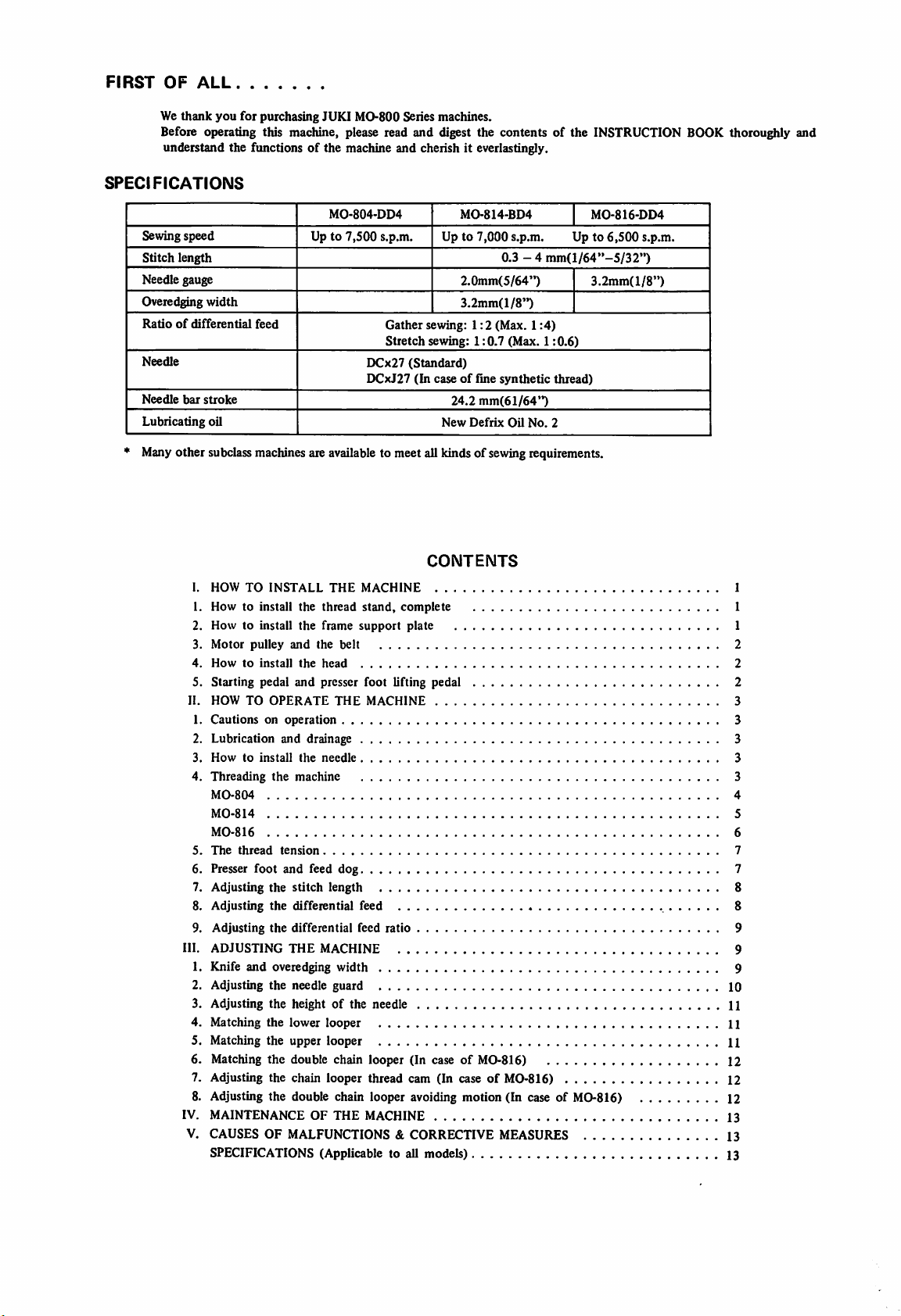
SPECIFICATIONS
of
the machine and cherish it everlastingly.
Sewing speed
Stitch
length
Needle gauge
Overedging
Ratioofdifferential
Needle
Needle
Lubricating
bar
width
stroke
oil
feed
MO-804-DD4
Up to 7,500 s.p.m. Up to
Gather
Stretch
DCx27
(Standard)
DCxJ27
sewing:
sewing:
(In
caseoffine
New
MO-814-BD4
7,000
0.3 - 4
2.0mm(5/64")
3.2mm(l/8")
1:2
(Max.
1:0.7
synthetic
24.2
mm(61/64")
Defrix
s.p.m. Up to
mm(l/64"-5/32")
1:4)
(Max.
1:0.6)
thread)
Oil
No.
2
MO-816-DD4
3.2mm(l/8")
* Manyother subclassmachines are availableto meet all kinds of sewingrequirements.
CONTENTS
HOW
TO
INSTALL
How to install the
How to install
Motor
pulley
Howtoinstall
Starting pedal
HOW
TO
OPERATE
THE
MACHINE
thread
stand,
complete
the
frame
support
and
the
belt
the
head
and
presser foot lifting pedal 2
THE
plate
MACHINE
Cautionsonoperation
Lubrication and drainage 3
Howtoinstall
Threading
MO-804
MO-814
MO-816
The
thread
5.
Presser
6.
7.
Adjusting
Adjusting
8.
Adjusting
9.
III.
ADJUSTING
1.
Knife and overedging width 9
2.
Adjusting the needle guard 10
3.
Adjusting the height
4.
Matching
Matching the upper looper 11
5.
6.
Matching the double chain looper (In case of MO-816) 12
7.
Adjusting the chain looper thread cam (In caseofMO-816) 12
Adjusting the double chain looper avoiding motion (In case of MO-816) 12
8.
IV.
MAINTENANCE OF THE MACHINE 13
V.
CAUSES OF MALFUNCTIONS & CORRECTIVE MEASURES 13
the
needle
the
machine
tension
foot
and
feed dog 7
the
stitch
length
the
differential feed 8
the
the
THE
lower
differential
feed
ratio
MACHINE
of
the needle 11
looper
SPECIFICATIONS (Applicable to all models) 13
6,500
s.p.m.
1
1
1
2
2
3
3
3
3
4
5
6
7
8
9
9
11
Page 3
I. HOW TO INSTALL
THE
MACHINE
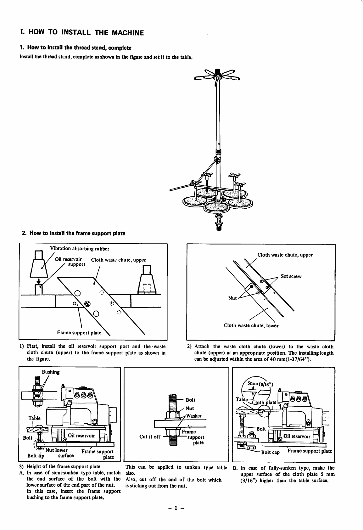
1. Howtoinstall
Install the thread stand, complete asshown in the flgure and set it to the table.
the
thread
stand, complete
—
2. Howtoinstall
1) First, install the oil reservoir support post and the-waste
cloth chute (upper) to the frame support plate as shown in
the figure.
Bushing
the
frame
support
Vibration absorbing rubber
Oil reservoir Cloth waste chute, upper
support
Frame
support
plate
plate
m
Table
i.
Bolt
-
"T"
Nut
Bolt tip surface
3) Heightofthe frame
A. In caseofsemi-sunken type table,
the
end
this
surface
case,
lowersurfaceofthe
In
bushingtothe
E
lower
insert
frame
Oil
support
of
end
reservoir
Frame
the
partofthe
the
support
a
X
plate
bolt
frame
plate.
•
support
plate
match
with
nut.
support
This can be
iJso.
the
Also,
is sticking
Cutitoff
applied
cut off the end of the bolt
out
from
2)
Attach
chute (upper) at an appropriate position. The installing length
canbeadjusted
esa
—
Bolt
^
Nut
M
the
J^Washer
Frame
'support
plate
to sunken type table B. In
which
the
nut.
- 1 -
Cloth
waste
within
Cloth
waste
chute,
lower
cloth
chute
(lower)tothe
the
areaof40
5mm(3/i6")
v^CLoth
plate
Bolt
caseoffully-sunken
upper
surface
(3/16")
higher
waste
chute,
upper
Set
screw
waste
cloth
mm(i-37/64").
Oil
cap
reservoir
Prame
I
support
plate
type, make the
of the cloth plate 5 mm
than the table
surface,
Page 4
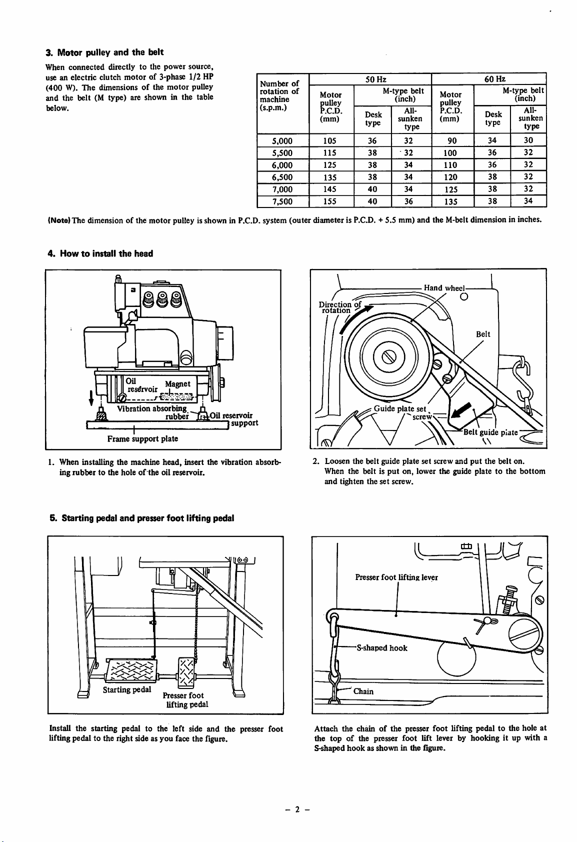
3. Motor pulley
When
connected
and
the
belt
directlytothe
power
source,
use an electric clutch motor of 3-phase 1/2 HP
(400 W). The dimensionsofthe
motor
pulley
and the belt (M type) are shown in the table
below.
Number
rotation
machine
(s.p.m.)
5,000
5,500
6,000
6,500
7,000
7,500
60
Desk
type
34
36
36
38
38
38
Hz
M-type
(inch)
All-
sunken
type
30
32
32
32
32
34
belt
50
Desk
type
36
38
38
38
40
40
Hz
M-type
(inch)
All-
sunken
type
32
32
34
34
34
36
belt
Motor
pulley
P.C.D.
(mm)
90
100
110
120
125
135
of
of
Motor
pulley
P.C.D.
(mm)
105
115
125
135
145
155
(Note)The dimension of the motor pulleyisshown in
4.
HowtoInstall
I. When installing the machine
ing
rubber
the
head
Vibration
Frame
1
support
absorbmg
rubber
plate
head,
.11
jB:'
insert the vibration absorb
to the holeofthe oil reservoir.
Oil
reservoir
2
P.C.D.
support
system(outer diameteris
Direction
rotation
2.
Loosen
When
and
tighten
P.C.D.
of
/a
the
the
+ 5.5 mm) and the
Guideplateset
belt
guide plate
beltisput
the
set
on,
screw.
screw
lower
Hand
set
V—
screw
the
M-belt
dimensionin inches.
wheel
and
put
the
guide
platetothe
belt
on.
bottom
5.
Starting
pedal
Starting
and
presser
pedal
foot
Presser
lifting
foot
pedal
lifting pedal
Install the starting pedal to the left side and the presser foot
lifting pedal to the right sideas you face the flgure.
Presser
foot
lifting
lever
S-shaped
Cjiain
hook
Attach the chain of the presser foot lifting pedal to the hole at
the top of the presser foot lift lever by hooking it up with a
S-shaped
hookasshown
in the figure.
- 2 -
Page 5
n.
HOW
TO
OPERATE
1.
Cautionsonoperation
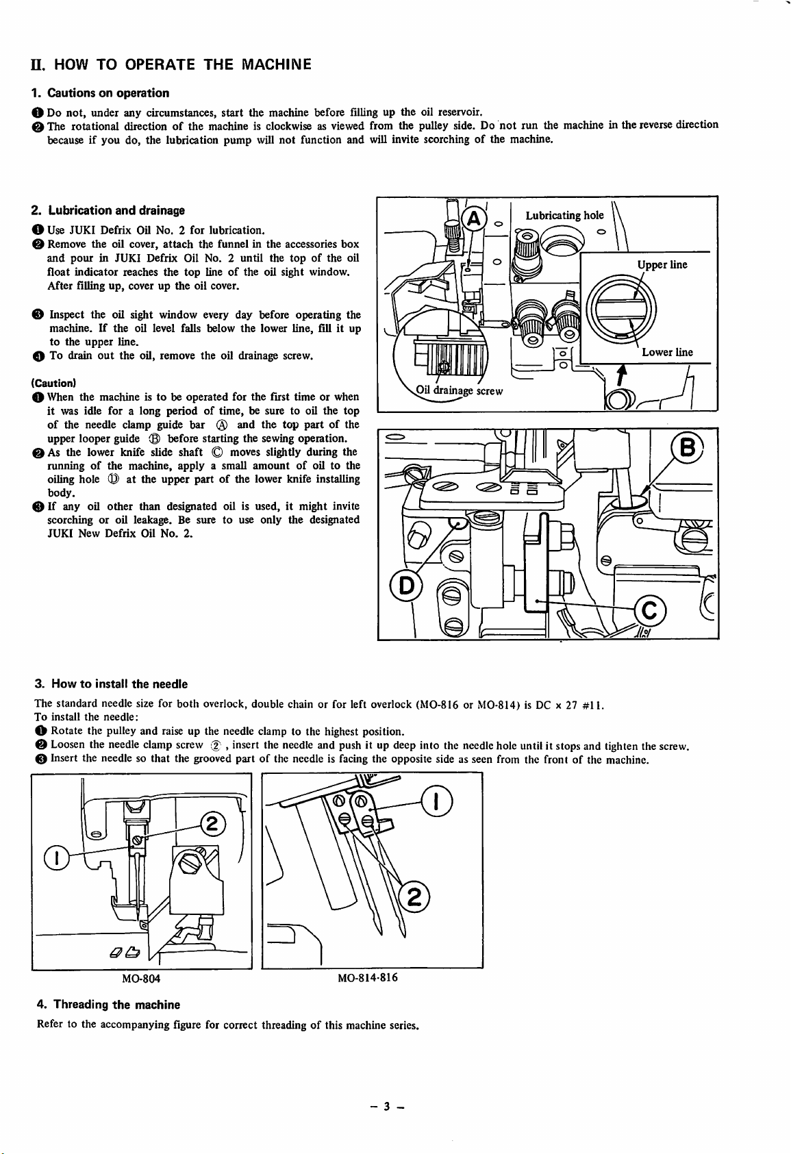
O Do not, under any circumstances, start the machine before filling up the oil reservoir.
e The rotational direction of the
because if you do, the lubrication pump will not function and will invite scorchingofthe machine.
2.
Lubrication
O Use JUKI Defrix Oil No. 2 for lubrication.
Remove
and
pourinJUKI
float
After
the
indicator
filling
and
drainage
oil cover,
reaches
up,
cover up
Defrix
attach
the
the
THE
MACHINE
machineisclockwiseasviewed
the funnel in
Oil No. 2
top
lineofthe
oil cover.
the
accessories
until
the
topofthe
oil sight window.
box
oil
from the
pulley
side. Do not run the
0 Inspect the oil sight window every day before operating the
machine.Ifthe oil level falls below the lower line, fill it up
to
the
upper
0 To drain
out
line.
the
oil, remove
the
oil drainage screw.
machine
Lubricating hole
in the
reverse
Upper line
Lower
direction
line
(Caution)
O When the machine is to be operated for the first time or when
it
was idle
of the needle clamp guide bar @ and the top part of the
upper looper guide 0 before starting the sewing operation.
foralong
periodoftime,
be sure to oil
the
top
Oil drainage screw
0 As the lower knife slide shaft © moves slightly during the
runningofthe machine, apply a small
amountofoil to the
oiling hole 0 at the upper part of the lower knife installing
body.
0 If any oil
scorching or oil leakage. Be sure to use only the designated
JUKI
New
other
than designated oil is used, it might invite
Defrix
Oil
No.
2.
0
3.
HowtoInstall
The standard needle size for both overlock, double chain or for left overlook (MO-816 or MO-814) is DC x 27 #11.
To
install
the
O Rotate the pulleyand
0
Loosen
0 Insert the needle so
the
needle:
needle
the
needle
raise
clamp
up the needleclamp to the
screw
that
the grooved partofthe needle is facing the opposite side as seen from the front of the machine.
,
insert
the
needle
highest
and
push
position.
it up
deep
into the
needle
hole
untilit
stops
and
tighten
the
c
screw.
©
MO-8I4-816
4.
Threading
MO-804
the
machine
Refer to the accompanying figure for correct threading of this machine series.
- 3 -
Page 6

MO-804
1. Ovcrlock needle iliread is No. 1 and is shown in red color.
2. Upper looper thread is No. 2 and is shown in blue color.
3. Lowerlooper thread is No. 3 and isshown in yellow color.
- 4 -
Page 7

MO-814
1.
Left
side
needle
threadisNo.1andisshowninred
2. Right side needle thread is No. 2 and is shown in
3.
Upper
4.
Lower
looper
looper
threadisNo.3andisshowninblue
thread
is No. 4
and
is si.
owninyellow
color.
green
color.
color.
color.
a
- 5 -
Page 8

MO-816
1.
Overlock
2.
Double
3.
Upper
4.
Lower
5.
Double
needle
chain
looper
looper
chain
threadisNo,Iandisshown
needle
thread
is No. 2
threadisNo,3andisshowninblue
thread
is No, 4
looper
threadisNo,5andisshowninblack
andisshown
andisshowninyellow
in
red
color.
in green
color.
color.
color.
color.
Q)
- 6 -
Page 9

5.
The
thread
tension
The thread tension varies according to the kinds of sewing material, thickness and kinds of sewing thread, overedging width, stitch
length
and
etc. and therefore the pressureofthe thread tension disc
must
be adjusted in each individual case.
MO-804
(1)
Overlock
(2) Upper looper thread should be adjusted by tension
(3)Lowerlooper thread should be adjusted by tensionknob @ .
(4)Double chain needle thread or left side overlockneedle thread should be adjusted by tension knob @ . (In case of
(5) Double chain looper thread should be adjusted by tension knob (5). (In case of MO-816)
needle
threadshouldbe
adjustedbytension
knob 0 .
knob®
MO-814
.
0 ® ©
MO-816
MO-816orMO-814)
6. Presser
(1)
*
When
to the original position, be sure to knock down the presser lifting lever toward front.
(2)The standard protrusion of the feed dog from the throat plate surfaceis 0.8 mm(l/32").
For heavy
The
height
lower
(3) Adjusting
Remove
hole ® of the eccentricshaft (D and rotated, the
Also,
from
The
foot
pressure
the
presser
weight
protrusion
ofthe
than
this height.
the
the rear side
in so
doing,
the
holeofthe
and
feed
dog
ofthe
presser
footis
adjustediby
foot is to be turned
materials, makethe protrusionamount
amount
main
slantingofthe
can be
feed
dog0and
feed dog
cover
of the
loosen
the
screw
feed
mechanism cover, comes directly overhead.
adjusted
thesub
machine.
® and
sideways,
by the feed
feed
Then,
move
rotating
the
presser
knock down the
bigger
dog
dog®becomes
remove
slanting
the thrust
foot
adjusting
presser
and for lightweightmaterials makeit
set
screws(Dand 0 .
equal.
the rubbercap and
of the feed dogcan be adjusted. Afteradjustment,
collar
sothat the
The
screw
lifting
auxiliary
loosen
screw
lever
0 .
The
standard
® to the rear.
When
making
feed
dog0shouldbeinstalled
8)
the set
screw
of the
feed
pressure
When
less.
this
CIQ
0 . Ifa roundbarisinserted into the
barshaftthrust
is4.5
kg.
(9.9
the
presser
foot isreturned
adjustment,besure
0.5
mm(l/64")
tighten
theset
collar
(Q)
lbs)
that the
screw
coming
(f).
out
- 7 -
Page 10

(4)
Unless
the
bottom
plate are
become curved and the chain-off thread stitching of double chain stitch can not be
performed
surface
when the
surface. (In case of MO-816)
(Note)
*
When
snuggly
well.
of the
presser
sewmg
irigordamagetothe
pitch
flaworcontracted
surface
of the
presscr
foot ® and the
upper
surface
of the
contacting each other when the feed dog is lowered, the stitches may
Loosen
presser
light
the
presser
foot
hinge
foot ® drops little to right
foot is lowered, the bottom
weight
materials,ifthe
sewing
cloth
stitches
might
pressing
may
result.Onthe
result.Besuretomake
screw © and adjust so that the bottom
when
the
presser
foot is
surface
snuggly
pressureistoo
contrary,ifthe
contacts the throat plate
strongorthe
protrusion
pressureistoo
correct
adjustment.
raised
throat
and
amountofthe
weakorthe
feed
dogistoo
protrusionofthe
great,
feed
shrink
dogistoo
stitch-
small,
7. Adjusting
The stitch length can be adjusted by changing the eccentric amount of the feed cam.
the
stitch length
\i
/
csT
(1)As you keep
rotate
a
"click"
(2) As you keep pressing the
is carved in the pulley with the indicating point of the frame.
8.
Adjusting
Tlie differential feed
of the-sub feed. If the differential feed lever ® is pushed up, gather
stitching
stitching
(1)Push
and
rotateittowards
stops.
(2) Loosen the differential feed lock
differential feed lever ® either up or down, adjust to the desired
differential feed
feed
lock
(3)
Next,
direction
(The
*
The
subclass machines, which can adjust
the knee during the running of the machine, are also available.
pushing
the
pulley
toward
sound and the push
the
differential
ratioisadjusted
can be
can be
the
cam
performed
performed.
sub
feed
nut
(3).
push
the
and
rotateittoward
whichisinside
amount.
sub
the push button
the desired direction.
button
button,
feed
andifit's
stopper
lever (2)
the
reverse
After
adjustment,
feed
stopper
the
will
rotate
(T)
with your
will
enter
match the stitch length which
by changing
moved
downwards,
toward
direction
nut
lever (2)
arrow
and
the frame direction,
of
(3) and by moving the
tighten
direction
sets
it).
the
differential feed by
finger,
You
will
deep inside.
the
moving range
the
arrow
the differential
toward
the
untilitstops.
hear
stretch
until
(3) The figures carved in the pulley indicate the stitch length.
If the figure
point of the frame, the stitch length becomes approximately
3
it
frame
mm.
Indicating
"3"
of the pulley is matched with the indicating
(D
Gather
stitcl^^^
Stretch
n
stitching
- 8 -
Page 11

9.
Adjusting
The
standard
the
differential feed
differential
feed
ratio
ratioofthis
machine
Gatherstitching 1:2 Stretchstitching 1:0.7
When
this
1) Remove the cover
standard
2) Loosen the main feed arm pin setting nut (2).
3) Ifthe
(1)
main
When
feed
differential
(l)
arm
feed
on the backofthe
pin
ratioistobe
(3)ismovedupand
machine.
the main feed arm pin israised to highest point, the differentialfeedratio becomes:
Stretchstitching 1:0.6 Gatherstitching 1:1.7
When
(2)
(3)
the main feed arm pinis loweredto lowestpoint, the differentialfeedratio becomes:
Gather stitching
When
the differential
match
the
center
1:4
feed
ratioisto be
ofthenut @
with
the
is :
changed
down,
changed
carved
dueto
the
differential
to the
line
ofthe
changeofsewing
feed
ratio
standard
main
differential
feed
conditions,
changesasfollows
feed
ratio(stretch
arm
(J).
adjustasfollows
:
stitching
if)
:
1:0.7,
gather
stitching
1:2),
Maximum
for stretch stitching
ni.
ADJUSTING
1. Knife
(1)Onthe
and
overedging
lower
Loosen the lower knife set screw (D and insert the lower knife
(3)
into
in the
the surface of the
screw 0
the grooveofthe lower knife slide shaft (2) as shown
figure.
THE
MACHINE
width
knife
Make
the tip of the lower knife the sameheight as
throat
plate and tighten the lower knife set
differential
feed
Throat
//////////////.
ratio
I
plate
Lower
knife
Maximum
for gather stitching
differential
0
/tlA
feed
tiAnft
ratio
A
- 9 -
m
Page 12

(2) On
the
upper
To install the upper knife, push the lower knife slide shaft (D to the
left
side and tighten the set screw
O
Loosen
knife
the upper knife set
screw
(2).
(3)
and insert the upper knife @ into
the upper knife support (D.
@
Make
the width of knife
knife) little less than the desired
(dimension
from
overedging
needle
position to the upper
width and lightly stop the
upper knife by the upper knife set screw from above the upper knife
presser (6) and the upper knife guide (7) .
®
Next,
rotate the
position, adjust so that the tip of the upper knife comes to 1.5
below
the
O
When
the
@ Loosenthe lowerknifeslideset screw
®
Rotate
the
throat
plateorthe
* When sewing heavy weight materials, be sure to re-tighten the lower knife
shaft
set
(3) Adjusting the lower knife spring pressure (Refer to sketch below)
Loosen the nut
When
the
In
caseofheavy
When the overedging
In noon ni-
In case
When the adjustment is completed, tighten
(4) Overedging
The standard
is slightly larger than the width of knife)
pulley
and
when
lower
knife.
adjustmentiscompleted,
pulleybyhand
waste
screw
(2).
(Z)
overedging
unuT
of
light weight matenals-'
width
overedging
and
cloth
and adjust by the screw (8),
widthiswide-j
weight
materials^
width
is narrow-, ,
»• 1.* * • 1
width is 3.2 mm(l/8") but
the upper
securely
verify
cover.
ti^ten the
(2)
.
that
the
•Tighten
r""Loosen
nut
knife
(7).
has
knives
screw
screw
risen
to the topmost
upper
are
not
overedging
mm(l/16")
knife
set
screw.
touching
width of 6.35 mm(l/4") is
the
available
as a subclass,
(The
overedging
width
2. Adjusting
2 needle guards (§) (g) axe attached to the Model MO-804 and
Model
1)
Loosen
and left, adjust as shown in the figure.
2) Then, when the needle has dropped to the lowest position,
MO-814.
screw
the
needle guard
(D and by
moving
the
needle
guard® to right
adjust the front and rear slanting of the needle guard ® so
that the needle barely touches the needle guard. Then tighten
screw (D .
3) Adjust the needle guard (g) by loosening the screw (2) and
adjust in the same manner as the needle guard ®
needle
guardis(F)).
4) For
MO-816,
the needle guard(gwith screw @ by matching, respectively,
with
5) The up and down height of the needle guard ® needle
the
and needle guard ©(MO-816) and the slanting angle of these
guards should be adjusted, respectively, by loosening the
and
screw
Needle
double
(?).
adjust the
chain
needles.
needle
guard © with screw ® and
Double
chain
needle
Overlook
(MC)-814
guard©
screw®
needl6
I.Dmm
2.5mm
-
10
-
Page 13

3.
Adjusting
When
the
the heightofthe overlook needle is 10 mm(25/64")
from
the
the
heightofthe
needle
clamp
surfaceofthe
is at the
throat
topmost
plate.
needle
position,
u
4b Matching
(1) Standard radius
Loosen the set screw (D and adjust so
standard
to the blade
of
(2-41/64").
(2)
Fore
Adjustsothat
lower looper comes to 2
lightly tighten screw
(3) Clearance between the looper and the needle
Standard
Fine
Loosen the set screw @ , move the lower
looper
adjustsothat
pointoflower
needle
(4) Returning
MO-804-0D4^
MO-814-BD4J4mm(5/32
MO-816-DD4 6 mm(15/64")
Next,
extreme
between the blade
centerofthe needle (returning
to the above distance by loosening the screw
the
lower
looper
....
66.5mm(2-5/8")
that
radius
(distance
pointoflooper)ofthe blade point
the lower looper ® comes to 67mm
and
aft
slant
the
fore
from
2
mm(5/64")
and
aft
mm(5/64")
the
shaft
slantofthe
center
(D.
thread
synthetic
thread
support
comestothe
arm (2) fore
the
looper
amountoflower looper
. . .
clearance
and
ibove
^
0.05-0.1
under
between
back
dimension.
mm
0.05
mm
and
aft
the
sideofthe
)
when
left
the lower
position,
looper
comes to the
adjustsothat
pointoflooper
amount)
the distance
and
comes
® and (D
the
and
and
blade
the
l0min(2S/64")(MO-804)
In caseofsingle
®—
(D-n
(4>i
Overlook
needle
J ® /
W 2
fjj^\
needle
—
10tnm(
j
4mm(5/32")
h-
(804-814)
6mm(15/64')
mm
25/64")
^
Q
(MO-814)
In
caseoftwin
10mm(25/64")<MO-8I6)
needles
Lower
looper
\ 0
• ~ ±
I
.05—0
—r
.limn
Matching
5.
(1) Heightofupper looper
the
upper
looper
....
llmm(7/16")
When the upper looper (D comes to the
extreme
left
position, loosen the
upper
looper
support arm set screw ® and adjust so that
the
distance
and
the
(7/16").
(2) Next, when the upper looper is rising, adjust
so
that
lower looper (2) comes to
throat
the
between
plate surface
clearance
the
with
looper
comes
the
about
back
blade
to 11mm
surface
0.1 mm
point
of
and lightly tighten screw @
(3) Protruding amount of upper looper...4mm(5/32")
When
the
upper
looper
left
position, adjust so
tween
the
blade
of
the
needle
ing
set
(4)Atthis
the
blade
throat
securely
screw @
(5)
Lastly, be absolutely sure
is
correctly
the
needleorlower
becomes4mm(5/32")
screw
(3)
time
re-verify
pointofthe
plate
surface is 11
tighten
matched
comestothe
the
that
that
upper
mm(7/16")
set
and
looper.
the
screw (3)
that
it is
pointoflooper
the distance be
distance
and
looper
the
the
upper
not
extreme
center
by loosen
between
and
the
and
then
and
set
looper
touching
4 mm Jto" )
f
/
0
11mm \
—
Needle
/ ^
(3)
\ \
1
Throat
plate
\ \
1
0
0 J
0
-
11
-
Page 14

6. Matching
the
double
chain
looper
(In case of MO-816)
O Loosen the double chain looper set screw (l)
and
A:
Adjustsothat
double
chain
(2-17/32")
the
standard
looper
(as high as possible as long as it
(2)
radiusofthe
becomes
64.5
doesn't touch the feed dog).
B:
Adjustsothatitslants
viewed from
screw ®
Next,
that:
A: When
from
blade
0.05—0.1
B: When
the
extreme
the blade
becomes
top
loosen
the
the
left
point
double
to right, the clearance between the
and
backsideofthe
mm.
the
double
left
position,
point
2.5mm(3/32")
and lightly tighten the
set screw (3)
and
1.5
mm(l/16")
and
chain
looper
needle becomes
chain
looper
the
the
centerofthe needle
by adjusting
has
distance
adjust
(2) moves
reached
between
the
double
chain looper support arm ® . Then, tighten
the
set
screw lightly.
When
allofthe
pleted,
verify
moves from
at the tip
the
centerofthe
double
chain
each
other
above
adjustments
that the
left
of
the double chain
looper
as viewed
double
to right and when the hole
needle
that
and
the
from
the
chain
looper
looper
the
holeofthe
needle
topofthe
are
com
comes to
eye
slant.
Then, securely tighten the set screws (D and (3).
mm
as
set
so
®
meet
Double
chain
0.05—0.1mm
looper
5mm(I/I6')
2.5mm
Double
chain
^Needle
looper
7.
Adjusting
(in
When
adjust so
the
chain
caseofMO-816)
the
needle
has
that
the right
looper
thread
cam
reached
its
highest
position,
comerofthe straight line
partofthe chain looper thread cam (2) matches
with the
upper
surfaceofthe chain looper thread
guide (D . Loosen the chain looper thread cam
screw (D and adjust the cam.
8.
Adjusting
the
double
chain
looper
avoiding motion (MO-816 Series)
Dependingonthe
the
double
changed
1.
2.
as follows:
Fore
and
For
heavy
(MO-816-DH6,
For
standard
(MO-816-DD4
Adjusting
O Remove the cover (D in the back of machine.
@ Loosen the screw® of the chain looper shaft slide arm.
0 Insert a bar of 2 0 into the hole oKBand rotate it.
size
looper
and
avoiding
chain
aft looper avoiding
weight
materials
FF6
Series)
weight materials
Series)
method
numberofneedle,
motion
can be
motion
Looper
avoiding
2.80-3.06
2.64-2.85
motion
mm
mm
Whenthe mark©is in front looper avoidingmotion is least
When the
opposite
mark©is
side
in the
looper
greatest
avoiding
motion
O After adjustment, securely tighten screw ®
Numberofneedle
#14-#21
#7-#16
is
-
12
-
Page 15

IV.
MAINTENANCE
OF
THE
MACHINE
O As the knife of the machine cuts the cloth, much waste cloth will be produced, so clean the machine at least once a day.
Dust and thread hards are liable to be collected especially in the clearancesofthe
throat
plate and clean it thoroughly at least once a week.
throat
plate, needle guard aMl feed dog, so remove the
0 Inspect the machinehead at leastonce a year and operate the machinein perfectlymaintainedcondition.
V.
CAUSES
No.
Malfunctions
1.
Needle
breaks
2.
Inadequate
cutting
knives
3.
Stitches
skip
4.
Thread
breaks
5.
Inadequate
chain-off
of
chain
(MO-816)
6.
Wrinkled
stitches
7.
Uneven
stitches
double
of
stitch
OF
MALFUNCTIONS
Reasons
(1) Wrong needle
(2)
Wrong size
(3)
Needle installed wrong
(4)
Needleiscurved
(5) Wrong
number
relation
needle used
with
needle
(6) Wrong relation with needle &
(1)
Inadequate
knives
(2)
Knives
(1) Relationofneedle
(2) Knife
(3) Needle
(4)
Inadequate
installationofupper
are
worn
out
with
pointoflooper is blunted
threadisright
adjustmentofthread
twist
(5) Inadequate adjustmentofchain looper
thread
cam
(MO-816)
(1)
Inferior
(2)
qualityofthread
Threadisthicker
than
(3) Inadequate installation of needle
(4)
Thread
(5)
Needle,
bruised
tension is
looper,
too
throat
strong
(1) Inadequate installation of presser
thread
(2)
Rattleofrear
(3) Inadequate timingoflooper thread cam
(4) Inadequate installation
looper
(1)
Needle is
(2)
Thread
(3)
Pressing pressure is
weak
(4)
Feed
(5)
Knife
(6)
Differential
(1)
Flawinthe
(2) Inadequate thread tightening
(3) Needle
(4)
Inadequate
presser
too
thick
tension
too
dog
protruded
does
not
cut
feedisnot
thread
pointisblunted
pressing pressure
foot
strong
either
too
well
tension
(5) Inadequate height of feed dog
AND
guard
looper
needle
plate,
needle
of
double chain
too
much
matched
CORRECTIVE
looper
and
lower
tension
guard
foot
stongortoo
MEASURES
(1)
Use
only
(2)
Use
needle
(3) Refer to
(4)
Exchange
(5)
Adjust
chapteron"How
the
(6) Refer to the
(1) Refer to the
Corrective
the
designated
which
fits
with
new
guard
chapter
needle
on "Matching the
needle
chapteron"Knife
measures
needle
thicknessofcloth
to install
and
the
overedging
and
needle"
looper"
(2) Sharpen the lower knife and exchange the upper knife
(1) Refer to
(2)
Sharpen
(3) Change it to left twist thread
(4) Refer to chapter on
the
chapter
with
on "Matching the
oil
whetstoneorexchangeitwith
"The
thread
looper"
tension"
(5) Refer to the chapter on "Adjusting the chain looper thread
cam"
(1) Use
good
quality
(2) Change to
(3) Refer to the chapter on "How to install the needle"
(4) Adjust by
(5) Sharpen by oU whetstone or
(1) Refer to
(2)
Adjusttoeliminate
(3) Refer to chapter on "Adjusting the looper thread
(4) Refer to chapter on "Matching the double chain
(1) Use needle
(2)
Adjustbythread
(3) Adjust the pressure by turning the adjusting screw either to
rightorleft
(4) Lower the feed dog and match the height of the main feed
dog with the heightofsub feed
(5) Resharpen
(6) Refer to chapter on "Adjusting the differential feed"
(1) Use uniform size
(2) Strengthen the thread tension
(3) Exchange the needle with a sharp pointed needle
(4) Refer to chapter on "Presser foot and feed dog"
(5) Refer to chapter on "Presser
thread
appropriate
thread
chapter
appropriatetocloth
the
needle or
tension
on "Presser
rattle
tension
knife
thread.
nut
buffer
foot
nut
Clean up
foot
thread
and
and
the
and
feed
thread
thread
feed
using
dog"
path
dog"
thread
width"
new
cam"
looper"
looper
SPECIFICATIONS(Applicabletoall models)
Stitch length:
Differential
ratio:
Lower
knife
pressure:
Overedge
width:
Presser lifting
amount:
Needles:
Needle
bar
Upper looper:
Double
chain
stitch
mechanism:
Presser
foot:
Lubrication:
feed
stroke:
0.3-4.0mm(l/64"-9/64")
Ratioofauxiliary feed to main feed: Gathering:
Spring pressure adjusting system
Standard
Byusing
adjust up to 6.35
Max.
DCx27
24.2
3.2
mm(l/8")
gauge
sets (throat plate, presserfoot, feed dog,needleclamp) whichconform to the
7.0
mm(9/32")
(Standard),
mm(61/64'*)
mm(l/4")
Slide type (Possible to change the up and down strokeoflooper depending on thickness of the sewingcloth)
Built-in inside the machine and geared with the lower looper (MO-816)
Fixed
presser
Two-stage presser
foot
foot...
Automatic lubrication system by meansofgear pump (equipped with oil cooling fan)
(Push-button system)(By special specification, up to 5mm(13/64") possibly
1:2
(Max.
1:4)
1:0.6)
DCxl
DCxJ27
(For
Stretching: 1:0.7 (Max.
fine
synthetic
thread)
MO-804, MO-814
MO-816
-13-
overedging
width, possibleto
Page 16

S»W*9
nun
Head Office & Plant, 2-1, 8-chome, Kokuryo-cho, Chofu-shi, Tokyo, Japan
Business
Cable
Address:
Office:
JUKI
23,
Kabuki-cho,
JUKI
TOKYO
INIUSIRIAl
Shinjuku-ku,
Telex:
22967
Tokyo,
JUKITK
GO..ITO.
Japan
 Loading...