

Page 1
UUKI
LK-1850 SERIES
No.
1983.7
IV-19
High-Speed
ENGINEER'S
1-Needle
Bar
Tacking
Cylinder
Machines
MANUAL
Bed
Lockstitch
k
19
TOKYO
FOREIGN
JOKI
INOUSTRIAL
TRADE
BUSINESS
CO.,
DIV.
LTD
Page 2

PREFACE
This Engineer's Manual is written
maintenance
The
Instruction
a
garment
Adjustment",
is
not
coveredbythe
It is advisabletouse
Manual
when
of
the
machine.
Book
for
factory
contains
"HowtoAdjust",
Instruction
the
carrying
out
the
machine
detailed
relevant
the
maintenanceofthe
for
technical personnel
intended
operating
"EffectsofAdjustment",
Book.
Instruction
for
the
instructions.
Book
and
machine.
who
are responsible for
the
service and
maintenance personnel and operators at
This
and
various
Parts Book
manual
together
other
describes
information
with
this Engineer's
"Standard
which
Page 3
CONTENTS
1.
SPECIFICATIONS
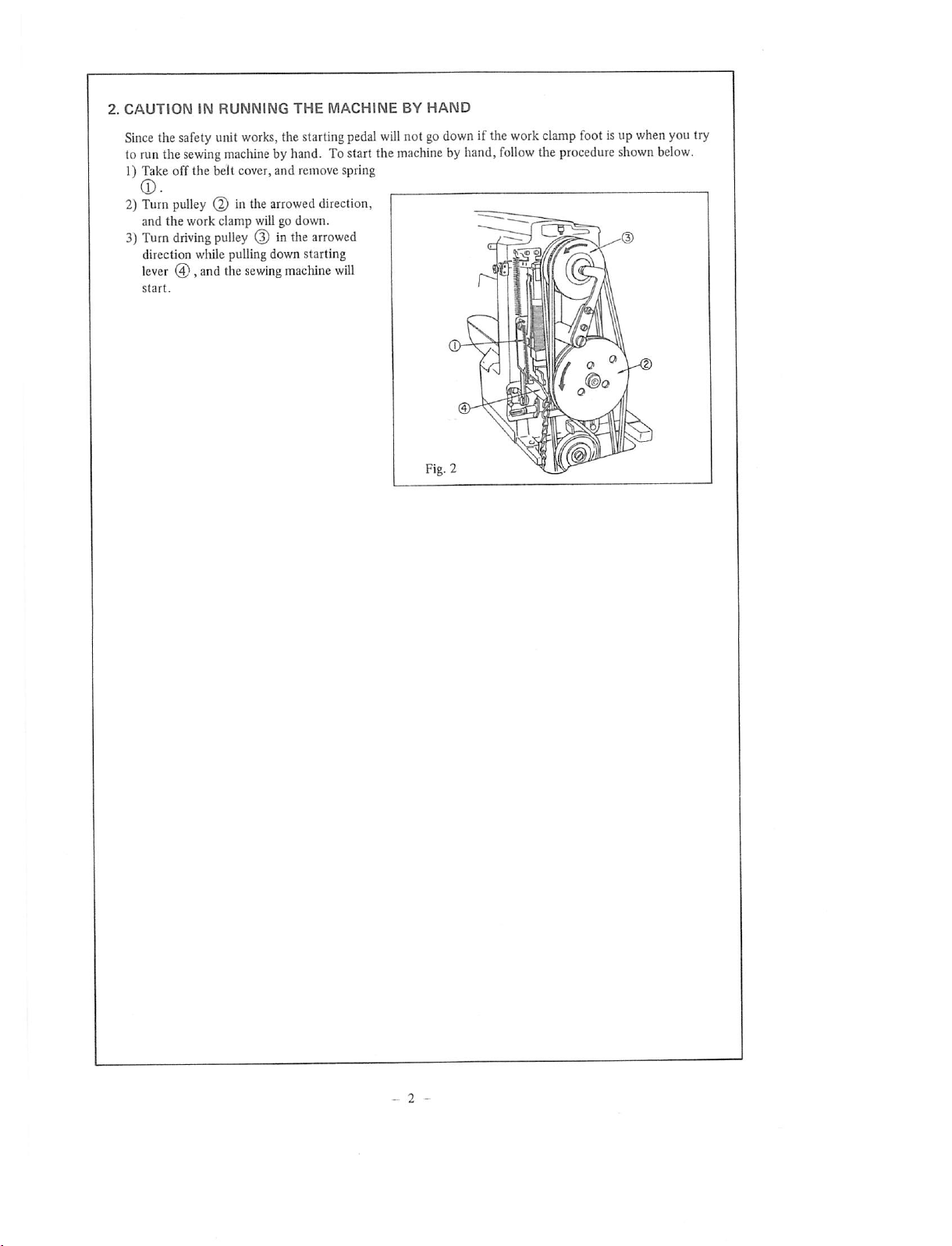
2. CAUTION IN RUNNING THE MACHINE BY HAND 2
3.
STANDARD ADJUSTMENT
4.
STANDARD
(1)
Height
(2) Adjustment of the feed cam 3
(3) Position of the stop-motion hook 5
(4) Stop-motion timing 5
(5) Adjustment of the changing pulley pressingplate 7
(6) Adjustment of the starting leverstopper 7
(7) Adjustment of the safety plate g
(8)
Position
(9)
Height
(10)
Position
(11)
Adjustment
(12)
Positionofthe
(13)
Adjustmentofthe
1)
2)
3)
4)
5)
(14)
Lateral
(15)
Adjustmentofthe
(16)
Positionofthe
(17)
Height of
(18)
Tiltofthe
(19)
Adjustmentofthe
(20)
Adjustmentofthe
(21)
Adjustmentofthe
(22)
Adjustmentofthe
5.
OTHER
(1)
Configurationofthe
(2)
Howtoremove
(3)
Howtoremove
(4)
Howtoremove
(5) How to remove
6. DISASSEMBLING & ASSEMBLING
(1)
Disassembling
(2)
Disassembling
(3)
Disassembling
(4)
Disassembling
(5)
Disassembling
(6)
Disassembling
(7)
Assembling
7. PARTS TO BE FIXED
8. PARTS TO BE FILLED
9.
EXPENDABLE
(1)
General
(2) Expendable PartsTo Be
(3) Parts
10. PARTS FOR
(1) Parts For
(2)
Special
(3) Modifying The Standard
11,
TROUBLES
ADJUSTMENT
of the
needle
ofthe work
ofthe
work
ofthe
ofthe
Timingofthe
Timingofthe
Clearance
Clearance
Clearance
between
between
between
positionofthe
the
moving knife and
counter
PRECAUTIONS
the
the
the
the
the
the
the
PARTS
ExpendableParts
Likely
To Be LostOr
SUBCLASS
Changing
Partsand
AND
CORRECTIVE
wiper
shuttle
moving
the
the
the
the
pedal pressure decreasing unit
FLOWCHART
bar 3
clamp
foot g
clamp
foot
tension
timing
needle
release
race
between
bar
spring
bar
the
needle
and
the
shuttle
shuttle
the
needle
and
the
shuttle
driver
the
needle
and
the
pointofthe
the
needle
and
the
shuttle
work
clamp
foot
auxiliary knife driving
knife
and
the
the
knife
blade
lengthofthread
thread
take-up
belt
tension
bobbin
winder
shuttle
race
ring
backlashofthe
backlashofthe
backlash
backlash of
shuttle
main shaft
speed reducer
high speed pulley (asm)
changing pulley •
low-speed pulley
WITH
WITH
MACHINES
The Numberof Stitches
Devices
between
the
PROCEDURES
driver
shaft
LOCKTITE
GREASE
Replaced
Damaged
Machine
To Subclass
cam
counter
counter
knife
knife
remainingonthe
spring
shuttle
feed bracket
Infrequently
main
the
During
driver
shaft
worm
Repair
Machine
shuttle
race
needle
shaft
and
the
AND
PRECAUTIONS
worm
gear
MEASURES
41
42
44
44
44
44
45
45
45
46
47
@
11
H
13
13
1g
1g
1g
1g
1g
15
iy
ig
19
2i
2i
23
23
25
25
25
25
27
27
29
2g
29
31
33
33
33
35
1
3
Page 4
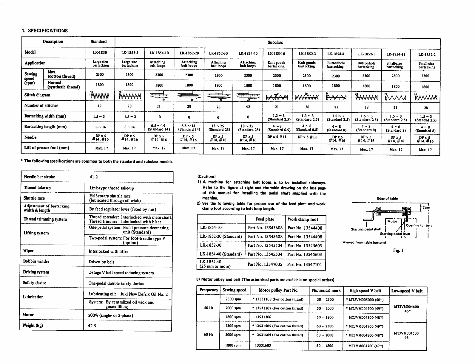
1.
SPECIFICATIONS
Description
Model
AppUcation
Sewing
speed
(spm)
Max.
(cotton thread)
Normal
(synthetic thread)
Stitch diagram
Numberofstitches
Bartacking
mdth
(mm)
Bartacking length (mm)
Needle
lift
of piesserfoot (mm)
* The following specifications are
NeetOe
bar
stroke
Thread take-up
Shuttle
race
Adjustmentof bartacking
width & length
Thread trimmingsystem
Liftingsystem
Wiper
Bobbin
winder
Drivingsystem
Safety device
Lubrication
Motor
Weight(kg)
Standard
LK-1850
Laig(>size
bartacking
2300
1800
LK-1852-5
Large-size
bartacking
2300
1800
LK-1854-10
Attaching
belt
'wmm
42
1.5
~3
8~I6
DPx5
#14.
#16
Max.
17
commontoboth
41.2
link-type thread take-up
Half-rotary shuttle race
(lubricatedthroughoilwick)
Byfeedregulator lever(fixed by nut)
Threadspreader: Interlocked with main shaft,
Thread
trimmer:
One-pedal
Two-pedal
system: Pedal
system:
Interlocked
Driven by belt
2-stage
Vbelt speed reducingsystem
One-pedaldouble safety device
Lubricating oil: Juki New Defrix Oil No. 2
System: By centralized oil wick and
greasefilling
2()0W
(single-or 3-phase)
42.5
28
1.5-3
8-16
DPx5
#14,#16
Max.
17
the
standard
Interlocked
pressure
unit (Standard)
Forfoot-treadle type P
(option)
with
lifter
and
6.5~14
(Standard
#14.
subclass
with
decreasing
2300
1800
DPx5
Max.
lifter
loops
21
0
#16
17
models.
14)
LK-1852-20
Attaching
belt
2300
1800
28
0
6.5
~ 14
(Standard
DPx5
#14,#16
Max.
Subclass
LK-185
loops
28
17
14)
Attaching
belt loops
2300
1800
28
0
13-25
(Standard
DPx5
#14.#16
Max.
2-30
17
25)
LK-1854-40
Attaching
belt
loops
2300
1800
1
42
42
0
18-35
(Standard
DPx5
#14.
Max.
#16
LK-1854-6
Knit
goods
bartacking
2300
1800
21
1.3-3
(Standard
2.5)
25)
17
4-8
(Standard
DP X5
Max.
6.5)
#11
17
(Cautions)
1) A
madiina
for attaching belt loops is to be installed
Refer to the figure at right and the table drawing on the last page
of this manual for installing the pedal shaft supplied with the
machine.
2) See the
3) Motorpulleyand belt (Theasterisked partsare
clamp
foot
LK-1854-10
following
table for proper use of the feed plate and work
according to belt loop length.
LK-1852-20 (Standard)
LK-1852-30
LK-l 854-40 (Standard)
LK-185440
(25 mm or more)
Frequency Sewingspeed
2300 spm *
50
Hz
2000 spm
1800 spm
2300 spm
60
Hz
2000 ispm
1800
spm
Part
Part
Part
Part
Part
*
*
*
Feed plate
No.
13543608
No.
13543608
No.
13545504
No.
13545504
No.
13547005
Motorpulley
13531108
13531207
13531306
13531405
13531504
13531603
(For
(For
(For
(For
Part
cotton
cotton
cotton
cotton
Work
Part
Part
Part
Part
Part
available
No.
thread)
thread)
thread)
thread)
LK-1852-3
Knit
goods
bartacking
2300
1800
28
1.3-3
(Standard
2.5)
4-8
(Standard
6.5)
DP X5
#11
Max.
17
sideways.
damp
foot
No.
13544408
No.
13544408
No.
13545603
No.
13545603
No.
13547104
on specialorders)
Numerical
m A A A 4
"i V V V vx
(Standard
(Standard
50-2300
50-2000
50-1800
60-2300
60-2000
60
1800
LK-1854-4
Buttonhole
bartacking
2300
1800
21
1.5-3
4-8
DPx5
#14.#16
Max.
mark
WWWV^
2.5)
(Standard
8)
17
Starting
(Viewed
from
High-speedV belt
• MTJVM005000
* MTJVM004900
MTJVM004800
•
MTJVM004900
•
MTJVM004800
MTJVM004700
LK-1852-1
Buttonhole
bartacking
2300
1800
28
1.5
4-8
(Standard
DPx
#14,
Max.
pedal
table
- 3
#16
5
17
2.5)
8)
Edge of
shaft
Starting
bottom)
(50")
(49")
(48")
(49")
(48")
(47")
LK-1854-11
Small-size
bartacking
2300
1800
21
TA
A A A S
kwwi
21
1.5-3
(Standard
4-8
(Standard
DPx
#14.#16
Max.
table
Motor
,
|
pedal
Fig. I
Low-speed V
MTJVM004600
MTJVM004600
2.5)
8)
5
17
in
Opening
/'
[ ' |
lever
46"
46"
LK-1852-2
Small-size
bartacking
2300
1800
bUUUUUVAl
riVVVVVV^
28
1.5-3
(Standrd
2.5)
4-8
(Standard
8)
DPx
5
#14.#16
Max.
17
forbelt
J |
belt
Page 5
Page 6
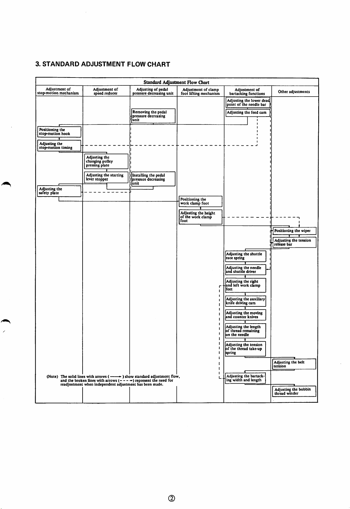
3.
STANDARD
Adjustment
stop-motion
Positioning the
stop-motion
Adjusting
stop-motion
Adjusting the
safety plate
(Note)
ADJUSTMENT
FLOW
CHART
Standard Adjustment Flow Chart
of
mechanism
hook
the
timing
The
solid
and the broken lines with arrows ( -•) represent the need for
readjustment
Adjusting
chan^ng pulley
pressing
Adjusting
lever stopper
lines
with
when
Adjustment
speed reducer
arrows
independent
of
the
plate
the
starting
( , ,
adjustment
Adjustingofpedal
pressure decreasing
Removing the pedal
pressure
unit
Installing the pedal
pressure decreasing
unit
) show
standard
has
decreasing
adjustment flow.
been
made.
Adjustmentofclamp
unit
foot lifting mechanism
Positioning the
work
Adjusting the height
of
the
foot
clamp
work
foot
clamp
Adjustment
bartacking functions
Adjusting the lower deat
pointofthe
Adjusting the feed cam
Adjusting the
race
spring
Adjusting
the
and
shuttle
driver
Adjusting the right
and left work clamp
feet
Adjusting
the
knife driving cam
Adjusting the moving
and
counter
Adjusting the
of thread remaining
on
the
needle
Adjusting
the
of the thread take-up
spring
Adjusting the
U.
ing width and length
needle
shuttle
needle
auxiliary
knives
length
tension
bartack
of
bar
Other
adjustments
t-
Positioning
Adjusting
release
Adjusting the belt
tension
Adjusting the bobbin
thread
bar
winder
the
the
wiper
teiuion
@
Page 7
4.
STANDARD
ADJUSTMENT
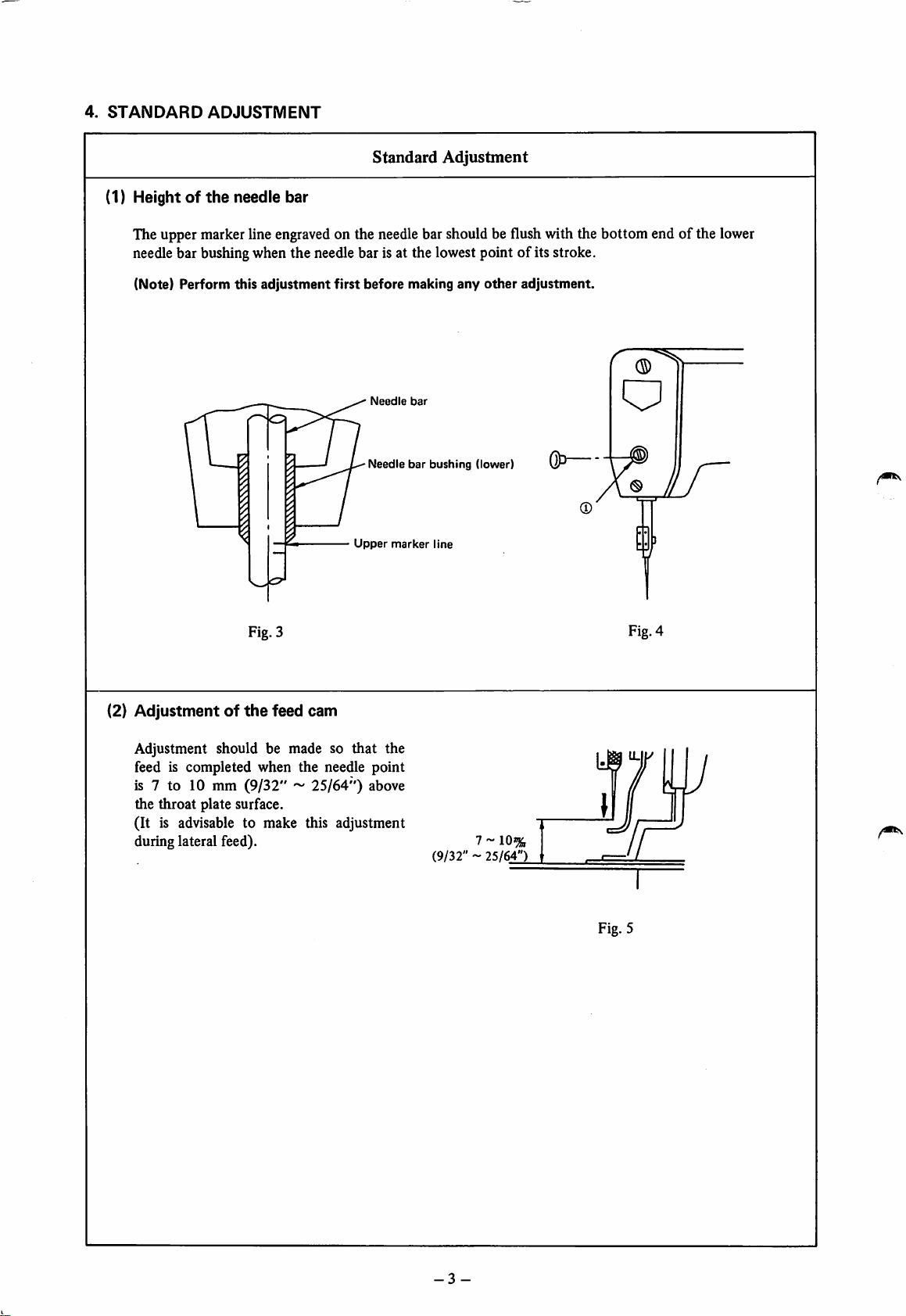
(1) Heightofthe
Standard
needle bar
Adjustment
The upper marker lineengraved on the needle bar should be flush with the bottom end of the lower
needle bar bushing when the needle bar is at the lowest point of its stroke.
(Note) Perform this
adjustment
first
before
Needle
Needle
Upper
making
bar
bar
marker
any
bushing
line
other
(lower)
adjustment.
&>—
E3
Fig. 3
(2)
Adjustmentofthe
Adjustment should be made so
feed cam
that
the
feed is completed when the needle point
is 7 to 10 mm
the
throat
(9/32"~25/64")
plate surface.
above
(It is advisable to make this adjustment
during lateral feed). ^ ~ 10%
(9/32"~25/64")
Fig. 4
Fig. 5
-3-
Page 8
HowtoAdjust
EffectsofAdjustment
1) Turn the drivingpulley by hand until the needle bar reaches the
lowest point of its stroke.
2) Remove the rubber plug from the face plate.
3)
Loosen
make the adjustment.
4)
After
setscrew
adjustment,
(T),and
securely
move
tighten
the
needle
setscrew
barupor
(T)
.
down
to
• Improper adjustment willcause
stitch skipping or thread breakage.
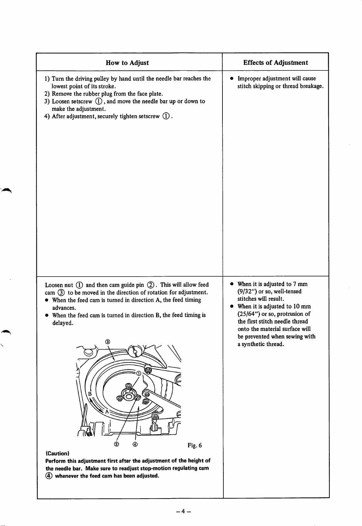
Loosen
nut
(T)
andthen cam
guide
pin .
This
will
allow
feed
cam (3) to be movedin the direction of rotation for adjustment.
• When the feed cam is turned in direction A, the feed timing
advances.
• When the feed cam is
delayed.
turned
in direction B, the feed timing is
%
(Caution)
Perform this adjustment first after
the
needle bar. Make suretoreadjust
whenever
the
feed
cam
has
been
®
the
adjustment of
stop-motion
adjusted.
Fig.
6
the
height of
regulating cam
Whenit is adjusted to 7 mm
(9/32")
stitches
Whenit is adjusted to 10 mm
(25/64") or so, protrusion of
the
onto
be prevented when sewing
a synthetic thread.
or so, well-tensed
will
result.
first
stitch
needle
the
material
thread
surface
will
with
-4-
Page 9
(Note)
Strictly follow
the
orderofadjustment
Standard
Adjustment
for (3) through (6) shown below.
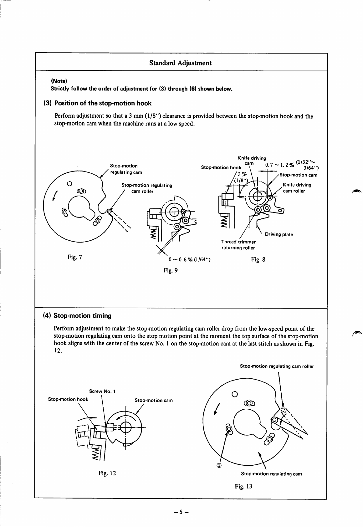
(3) Positionofthe
stop-motion
hook
Perfonn adjustment so that a 3 mm (1/8") clearanceis provided between the stop-motion hook and the
stop-motion cam when the machine runs at a low speed.
Knife
driving
Stop-motion
regulating
Stop-motion
cam
cam
roller
regulating
Stop-motion
hook
'Wl
cam
'3
0.7
~ 1. 2 %
Stop-motion
,Knife driving
cam
%
Driving
plate
Thread
trimmer
Fig, 7
0-0.
Fig. 9
5%
returning
(1/64")
roller
Fig. 8
3/64")
cam
roller
(4) Stop-motion timing
Performadjustment to make the stop-motion regulating cam rollerdrop from the low-speed point of the
stop-motion regulatingcamonto the stop motion point at the moment the top surface of the stop-motion
hook
aligns
withthe centerofthe
12.
Screw
No.
1
Stop-motion hook Stop-motion cam
screw
No.
1on the
stop-motion
cam
at the laststitchas
Stop-motion
showninFig.
regulating
cam
£
Fig. 12
Stop-motion
Fig. 13
regulating
roller
cam
-5
-
Page 10
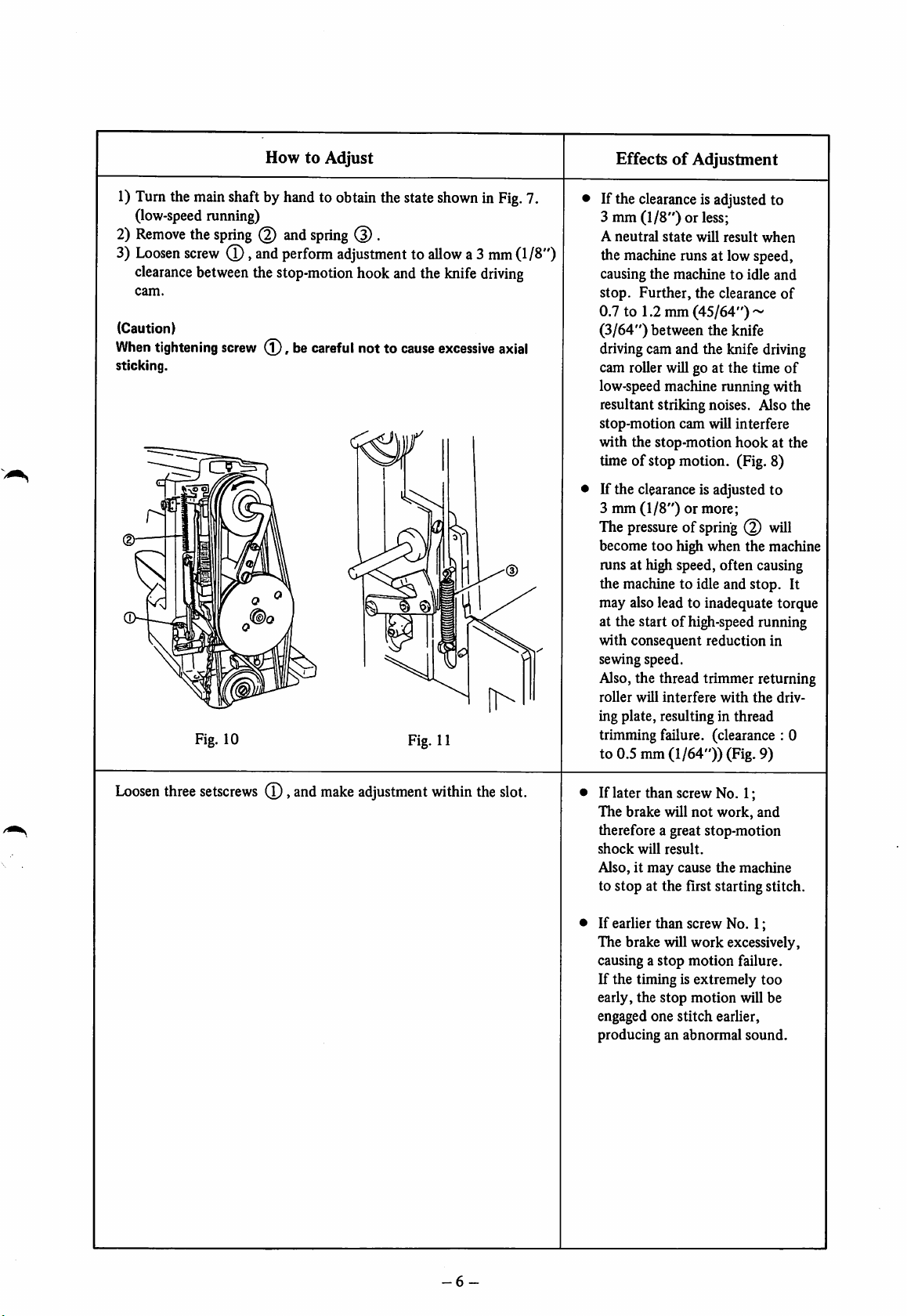
1)
Turn
the
main
(low-speed running)
2)
Remove
3)
Loosen
clearance
cam.
(Caution)
When
sticking.
the
screw
between
tightening
Fig. 10
HowtoAdjust
shaftbyhandto obtainthestate
spring
(2)
and
spring
(D .
(T),
and
perform
adjustmenttoallowa3mm
thestop-motion hook andthe
screw
(l),becareful
not to
showninFig.
cause
Fig. 11
knife
driving
excessive
(1/8")
axial
7.
EffectsofAdjustment
If the clearanceis adjusted to
3 mm (1/8") or less;
A
neutral
the machine runs at low speed,
causing the machine to idle and
stop.
state
Further,
will
result
when
the clearance
of
0.7 to 1.2 mm(45/64") ~
(3/64")
drivingcam and the knife driving
cam roller willgo at the time of
low-speedmachine running with
resultant striking noises. Also the
stop-motion
with the stop-motion
time of stop motion. (Fig. 8)
between the knife
cam
will interfere
hook
at the
If the clearanceis adjusted to
3 mm
(1/8")
or more;
The pressure of spring will
become too high when the machine
mns at high speed, often causing
the machine to idle and stop. It
may alsolead to inadequate torque
at the start of high-speedrunning
with consequent reduction in
sewing speed.
Also,the thread trimmer returning
roller
will
interfere
ing plate, resulting in thread
trimming failure, (clearance : 0
to 0.5 mm
(1/64"))
with
(Fig. 9)
the
driv
Loosen
three
setscrews
(D,
and
make
adjustment
within
the
slot.
• If later than screw No. 1;
The brake will
therefore a great stop-motion
shock
will
Also, it may cause
to stop at the first starting stitch.
• If earlier than screw No. 1;
The brake will work excessively,
causing a
If the timing is extremely
early, the stop motion will be
engaged one stitch earlier,
producing an abnormal sound.
result.
stop
not
work,
the
motion
machine
failure.
and
too
-6
Page 11
Standard
Adjustment
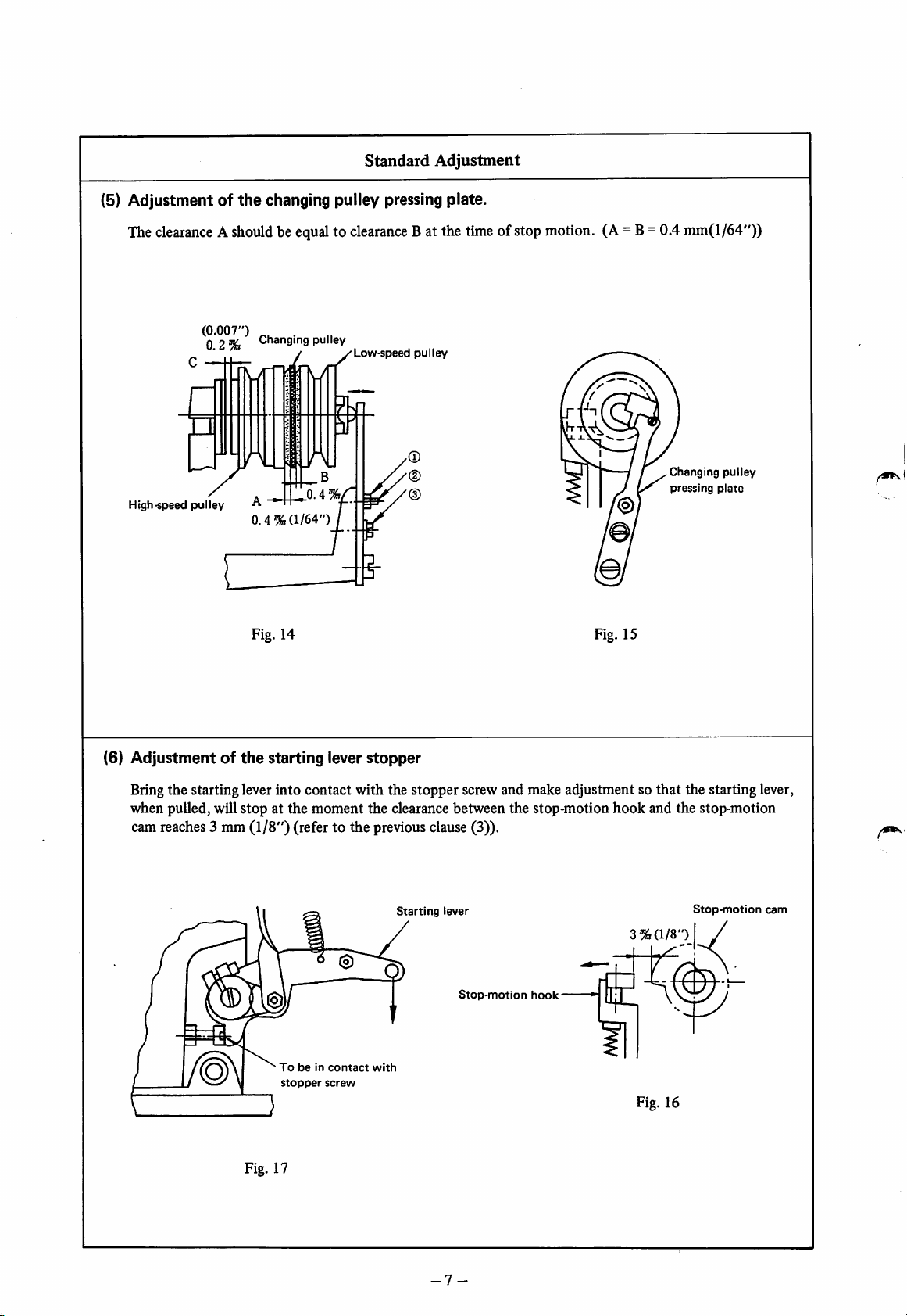
(5) Adjustment of
The
clearanceAshouldbeequaltoclearance
(0.007")
0 2%
High-speed
pulley
the
changing pulley pressing plate.
Changing
fKTT
.
j
pulley
Low-speed
Bat the
pulley
time
ofstop
motion.
r\
B
^
0.4%
Fig. 14 Fig. 15
0.4'
(1/64")
(A=B=0.4mm(l/64"))
Changing
pressing
pulley
plate
(6)
Adjustmentofthe
starting lever
stopper
Bring the starting lever into contact with the stopper screw and make adjustment so that the starting lever,
hook
when pulled, will stop at the moment the clearance between the stop-motion
and the stop-motion
cam reaches3 mm (1/8") (refer to the previous clause(3)).
(1/8")
Stop-inotion
I /
Tobein
stopper
contact
screw
with
Starting
lever
Stop-motion
hook-
3%
tn
Fig. 16
Fig. 17
cam
-7-
Page 12
HowtoAdjust
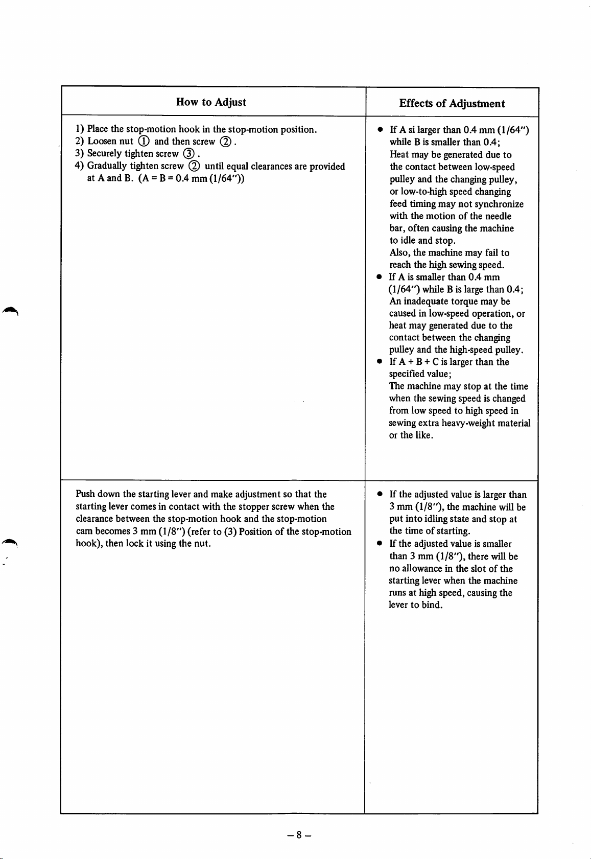
1)
Place
the stop-motion hook in the stop-motion position.
2)
Loosen
3)
Securely
Gradually
4)
nut
tighten
tighten
(T)
and
screw
screw
then
screw
(3).
untilequal
at A and B. (A = B= 0.4 mm (1/64"))
Q).
clearances
are
provided
EffectsofAdjustment
If A si larger than 0.4 mm
while B is smaller
Heat may be generated due to
than
the contact between low-speed
(1/64")
0.4;
pulley and the changing pulley,
or low-to-highspeed changing
feed timing may
with
the
motionofthe
bar, often causing the machine
to idle and stop.
Also, the machine may fail to
not
synchronize
needle
reach the high sewingspeed.
If
A is
smaller
than
0.4
mm
(1/64") while B is large than 0.4;
An inadequate torque may be
caused in low-speed operation, or
heat may generated due to the
contact between the changing
pulley and the high-speed pulley.
If A + B + C is larger than the
specified value;
The machine may stop at the time
when the sewing speed is changed
from low speed to high speed in
sewing extra heavy-weight material
or
the
like.
Push down the starting lever and make adjustment so that the
starting lever comes in contact with the stopper screw when the
clearance between the stop-motion
hook
and the stop-motion
cambecomes3 mm (1/8")(refer to (3) Position of the stop-motion
hook), then lock it using the nut.
If the adjusted value is larger than
3 mm (1/8"), the machine will be
put into idling state and stop at
the timeofstarting.
If the adjusted value is smaller
than 3 mm (1/8"), there will be
no
allowanceinthe
starting lever when the machine
runs at high speed, causing the
levertobind.
slotofthe
-8-
Page 13
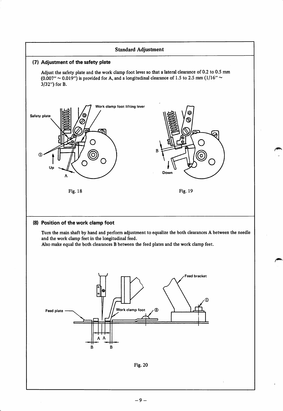
(7)
Adjustmentofthe
Adjust
the
(0.007"
3/32")
for B.
Safety
plate
safety
plate
~ 0.019")is
safety
andthe
provided
Work
Standard
plate
work
clamp
forA,anda
clamp
foot
Adjustment
foot
lever
longitudinal
lifting
lever
sothat a
lateral
clearanceof1.5
Down
clearance
to 2.5
@
!S!
of0.2 to 0.5
mm
(1/16"~
mm
Fig. 18
(8) Positionofthe
work
clamp
foot
Fig. 19
Tum the main shaft by hand and perform adjustment to equalize the both clearancesA between the needle
and the work clamp feet in the longitudinal feed.
Alsomake equal the both clearancesB between the feed plates and the work clamp feet.
Feed
bracket
Work
clamp
Feed
plate
foot
B B
Fig. 20
-9-
Page 14
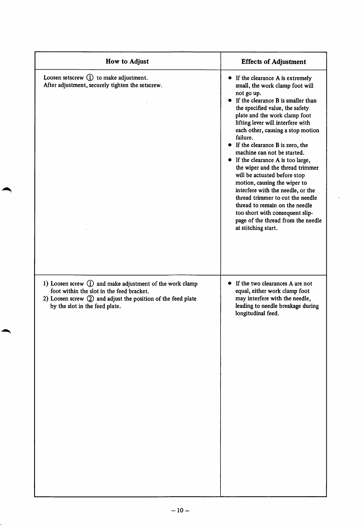
HowtoAdjust
EffectsofAdjustment
Loosen
setscrew
(T)tomake
adjustment.
After adjustment, securely tighten the setscrew.
If the clearance A is extremely
small, the work clamp foot will
notgoup.
If
the
clearance
B is
smaller
than
the specified value, the safety
plate and the work clamp foot
lifting lever will interfere with
each other, causing a stop motion
failure.
If
the
machine
clearance B is
can
zero,
notbestarted.
the
If the clearance Ais too large,
the wiper and the thread trimmer
willbe actuated before stop
motion, causing the wiper to
interfere
thread
threadtoremainonthe
with
the
needle,orthe
trimmertocut
the
needle
needle
too short with consequent slip
pageofthe thread from the needle
at stitching start.
1)
Loosen
foot
2)
Loosen
screw0and
within
the
screw0and
slotinthe
by the slot in the feed plate.
make
adjustmentofthe
feed
bracket.
adjust
the
position
ofthe
work
feed
clamp
plate
If
the
two
clearancesAare
not
equal, either work clamp foot
may
interfere
with
the
needle,
leading to needle breakage during
longitudinal feed.
-10-
Page 15
Standard
Adjustment
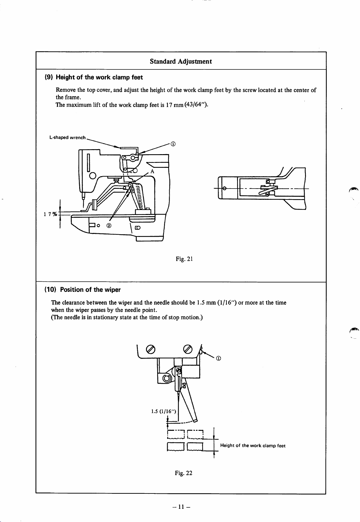
(9) Heightofthe
work
clamp
feet
Remove the top cover, and adjust the height of the work clamp feet by the screw located at the center of
the
frame.
The
L-shaped
maximum
wrench
lift ofthe work
clamp
feetis 17mm(43/64").
j/r^
r\
1 7
A
Fig. 21
(10) Positionofthe
wiper
The clearance between the wiper and the needle should be 1.5 mm (1/16") or more at the time
when the wiper passes by the needle point.
(The needleis in stationary state at the time of stop motion.)
o
1.5
(1/16")
j
;!
1
•czi
Fig. 22
-11
Height of
-
the
work
clamp
feet
Page 16
HowtoAdjust
EffectsofAdjustment
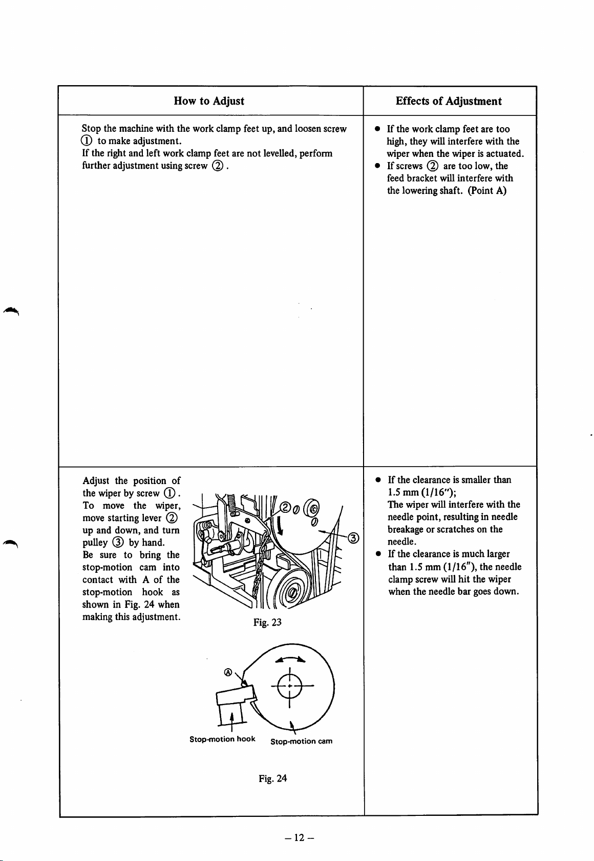
Stop the machine with the work clamp feet up, and loosen screw
(D to
make
adjustment.
If the right and left work clamp feet are
further
adjustment
using
screw
@ .
not
levelled, perform
If the work clamp feet are too
high, they will interfere with the
wiper when the wiper is actuated.
If
screws
feed
bracket
@ aretoo
will
low,
interfere
the
with
the loweringshaft. (Point A)
Adjust the position of
the
wiperbyscrew
To move the wiper,
move
starting
up and down, and
pulley
(3) by
Be sure to bring the
stop-motion cam
contact
stop-motion
shown in Fig. 24 when
making this adjustment.
withAof
lever
hand.
hook
(T)
(2)
turn
into
the
.
as
Stop-motion
Fig. 23
hook stop-motion
cam
If
the
clearanceissmaller
than
1.5nun (1/16");
The wiper will interfere
needle point, resulting in needle
breakage or scratches on the
needle.
If the clearance is
much
with
larger
the
than 1.5 mm(1/16"), the needle
clamp screw will hit the wiper
when
the
needle bar goes down.
Fig. 24
-12-
Page 17
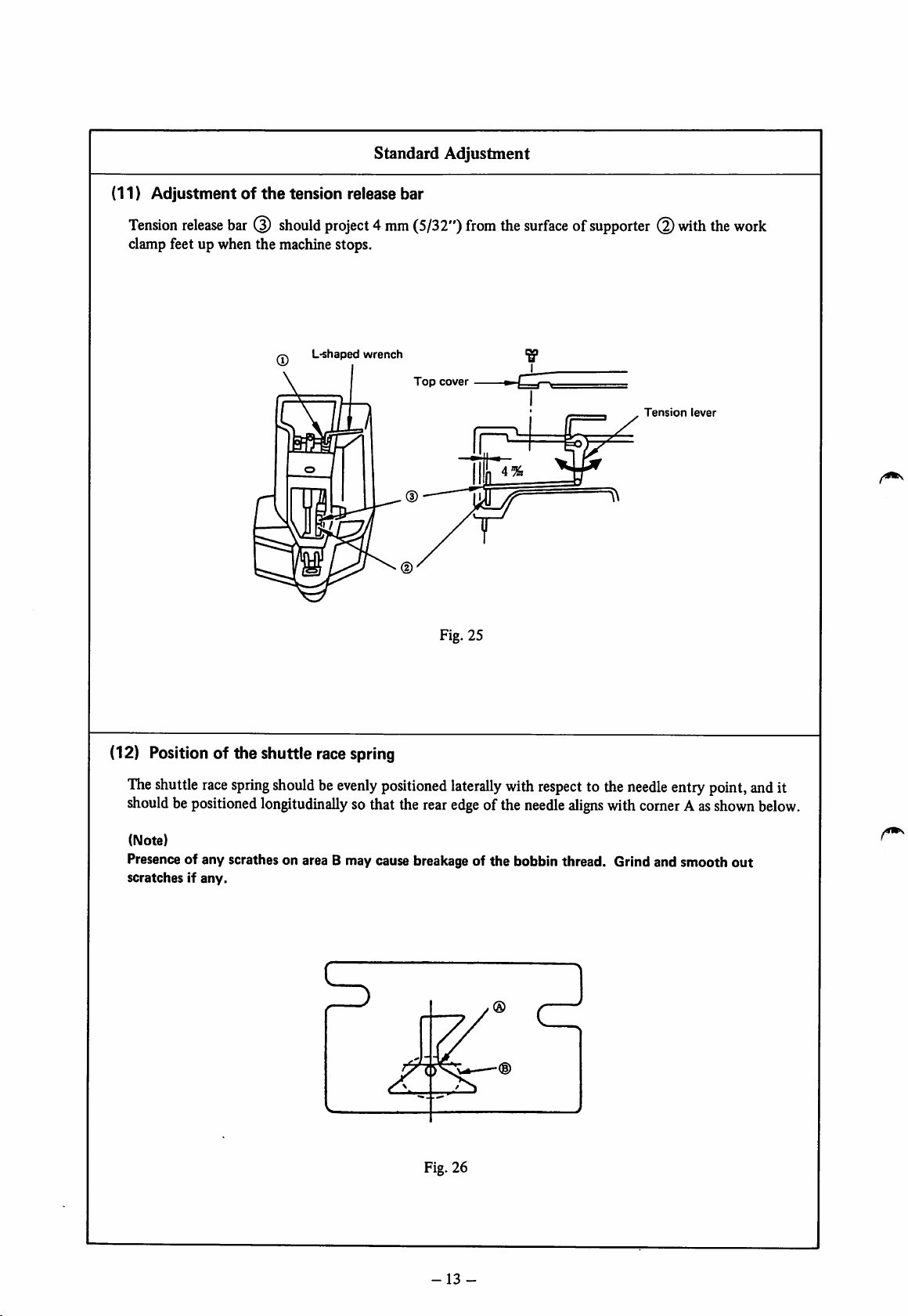
(11)
Adjustmentofthe
tension
Standard
release
Adjustment
bar
Tension
clamp feet up when the machine stops.
release
bar
(3)
should
L-shapedwrench
project4mm
(5/32")
Fig. 25
from
the
surfaceofsupporter
"g"
Tension
with
lever
the
work
(12) Position of the shuttle race spring
The
shuttle
shouldbepositioned
(Note)
Presence of any scrathes on area B may cause breakage of the bobbin thread. Grind and smooth
scratchesIfany.
race
spring
shouldbeevenly
longitudinally
positioned
sothat the
laterally
rear
edge
Fig. 26
with
ofthe
respect
needle
to the
aUgns
with
needle
corner
entry
Aas
point,
shown
out
and
below.
it
-
13
-
Page 18
HowtoAdjust
EffectsofAdjustment
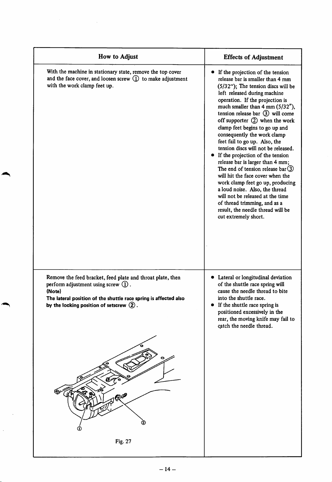
Withthe machine in stationary state, remove the top cover
and
the
face
cover,
and
loosen
screw
(T)tomake
adjustment
with the work clamp feet up.
If the projection of the tension
release
barissmaller
than4mm
(5/32"); The tension discswill be
left released during machine
operation. If the projection is
muchsmallerthan 4 mm (5/32"),
tension
off
release
bar (3) will come
supporter when the work
clamp feet begins to go up and
consequently the work clamp
feet fail to go up. Also, the
tension
discs
will
notbereleased.
If the projection of the tension
release bar is larger than 4 mm;
The end of tension
will
hit
the
face
cover
release
when
bar(3)
the
work clamp feet go up, producing
a
loud
noise. Also,
will
notbereleasedatthe
the
thread
time
of thread trimming, and as a
result,
the
needle
thread
will be
cut
extremely short.
Removethe feed bracket, feed plate and throat plate, then
perform
(Note)
The
bythe
adjustment
lateral
locking
using
positionofthe
positionofsetscrew
screw
shuttle
Fig. 27
(T)
.
race spring is
(^.
affected
also
Lateral or longitudinal deviation
of the shuttle race spring will
cause
the
needle
threadtobite
into
the
shuttle
race.
If the shuttle race spring is
positioned excessively in the
rear, the moving knife may fail to
catch
the
needle
thread.
-14-
Page 19

Standard
Adjustment
(13) Adjustment of
1) Timingofthe
Theneedle bargoesup from the lowestpoint of its stroke until the lowermarker line
the
needle
timing between
bar
the
needle and
the
shuttle
engraved
needlebar is flush with the bottom end of the needle bar bushing(lower). (Fig. 28)
2) Timing of
the
shuttle
Whenthe state is as described in the above 1), the center of the needle coincides with the point of the
shuttle at A. (Fig. 29)
3)
Clearance
between
the
needle
and
the
shuttle
driver
Whenthe state is as described in the above 2), there should be no clearance between the needle and the
shuttle driver. (Fig. 30)
4) Clearance between
the
needle and
the
pointofthe
shuttle
Whenthe state is asdescribed in 2), the clearance Bbetween the needle and the point of the shuttle
should
5)
Clearance
be0.05 to 0.1 mm(0.001" ~ 0.004")-
between
the
needle
arid
the
shuttle
(Fig-
race
31)
The clearance between the side face of the needle and the shuttle race should be 7.5 mm(19/64"). (Fig. 32)
1) Timing of
the
needle bar 2) Timing of
Shuttle
Needle
bar
Needle
bar
bushing
(lower)
the
shuttle
'0
Lower
marker
Fig. 28
line
on the
Fig. 29
3)
Clearance
the
Shuttle
Fig.
5)
shuttle
driver
30
Clearance
and
the
between
driver
between
shuttle
the
race
needle
the
7.5 %
needle
(19/64")
and
Shuttle
race
4)
Clearance
the
between
pointofthe
CD
©
shuttle
(D
the
needle
Fig. 31
0.3-0.5%
(0.011"-0.019")
and
0.0
5-0.1%
(0.001"-0.003")
Fig. 32
15-
Page 20

HowtoAdjust
1)
Referring
to Standard Adjustment (1)
Height
of the
needle
make the lower marker line engravedon the needle bar flush
with the bottom end of the bushing.
2)
and3)Loosen
setscrew
0 of
the
shuttle
driver,
and
adjust
the rotational and longitudinal directions of the shuttle driver.
(Caution)
Ensuretoturn
Fig.29when
the
shuttleinthe
adjusting
the
timingofthe
arrowed
directionasshown
shuttle.
4) Loosensetscrew (4) of the shuttle race, and turn eccentric
shaft
(D to
make
adjustment.
5)
Loosen
setscrew
0 to
perform
adjustment.
Enoughcare should be exercised whenperforming the
adjustmentdescribed in 4),
namely
the adjustmentof the
clearancebetween the needle and the point of the shuttle.
(Note)
The
clearanceinthe
and
the
shuttle
0.019") as shown in Fig. 29.
Strike
points
After
adjustment,
vertically
with
rotational
driver
shouldbe0.3
C or D
respecttothe
check
for
that
direction
mmto0.5
adjustment.
point
C is evenly spaced
shuttle.
between
mm
the
shuttle
(0.011
bar,
in
EffectsofAdjustment
1) and2)
Slightly
reduce
the height
of the needlebar (upper marker
line) for floppy material, and on
the contrary, slightly increase the
height for heavy-weight material
to adjust the timingofthe
shuttle.
(For prevention of stitch skipping)
3) If the clearance is more than 0
mm,
the
needle
will be
bent
the direction of the shuttle point,
causing scratches on
point
and
the
contrary,
contact
however, excessive
between
the shuttle driver may cause
the
shuttle
needle. On the
the
needle
stitch skipping.
4) If the clearanceis greater than
0.05 to 0.1 mm (0.001 ~ 0.003"),
stitch skipping will occur. If it is
smaller than the specifled values,
the needle strikes the shuttle point
and scratches occur, leading to
thread breakage or fine splits of
thread.
5) If the clearance is smaller than
7.5 mm(19/64") the needle
thread will
not
be fully spread,
often causing the needle thread
to
bite
into
the
shuttle.
in
and
Fig. 33
•Ifthe
shuttle
greater
clearance
drive
than
between
and
the
shuttle
0.3to0.5 mm
(0.011" ~ 0.019"), the shuttle
noise
willbelouder.
contrary,ifthe
enough, poorly tensed stitches
will result when sewing with a
thick
thread.
On
clearance is
the
is
the
not
-16-
Page 21

Standard
Adjustment
(14) Lateral positionofthe
The center of the work clamp foot should lie at the
the 18th stitch for 28-stitch large size bartacking.
Fig. 34
work
clamp
26th
stitch
(for
42-stitch
bartacking)
18th
stitch
(for 28-stitch large size
bartacking)
large size
foot
26th
stitch for 42-stitch large sizebartacking, and at
Fig. 35
(15) Adjustment of
The
clearance
(0.0H"~
between
0.019")
the
auxiliary knife driving cam
the
when
Changing
endofthe
roller©fits
pulley
auxiliary
inthe
knife
recess
driving
ofthe
<S)
cam
knife
Knife
and
roller(Dshouldbe0.3to0.5
driving
cam.
driving
cam
Auxiliary knife driving cam
Roller (2)
Roller
@
0.3-0.5%(0.0110.019")
(D
mm
Fig. 36
-17-
Page 22

HowtoAdjust
EffectsofAdjustment
Loosen
shaft in the arrowed directions for adjustment.
To conect slight deviation, loosen the lateral feed adjusting nut and
push the work clamp foot to the right or left to perform adjustment.
locknut
(T)
ofthe
feed
cam
roller
shaft,and
move
the
roller
• Improperly positioned center
the work clamp foot would cause
the needle to hit the work clamp
foot, leading to breakageofthe
needle.
of
1) Push down the starting lever, and manually turn the driving
pulley to lower the work clamp foot.
2) Further push down the starting lever,and turn the changing
pulley in the arrowed direction until roller fits in the recess
of
the knife driving cam.
3) Loosenthe setscrews,and make adjustment so that a clearance
of 0.3 to 0.5 mm (0.011"~ 0.019") is provided between the
end
ofthe
auxiliary
roller fits in the recess of the knife driving cam.
knife
driving
cam
and
roller
(3)
when
If
the
clearance is extremely
large, the thread trimming timing
will be delayed, resulting in
thread trimming failure.
Ifnoclearanceisallowed
the endofthe auxiliary knife
driving
trimming action will be inter
rupted at the timeofthread
spreading with resultant thread
cam
and
trimming failure.
roller
(3),
between
thread
-18-
Page 23

Standard
Adjustment
(16) Positionofthe
Positionofthe
Positionofthe moving knife
counter
moving knife
knife
The clearance between the counter knife and the needle hole guide
should be 0.5 mm (0.019")-
The needle hole in the needle hole guide should meet the hole in the
movingknife at the time of stop motion (before the work clamp foot
goesup).
Counter
Needle
guide
Moving
and
0.5%
(1/2")
hole
knife
the
knife
counter
knife
Moving
knife
link
(17) Height of
Moving
Counter
(18)
The
and bobbin thread).
knife : Engagement of the needlehole guidewith the
knife:Difference
Tiltofthe
counter
the
moving knife and the counter knife
between
the
needle
0.1 to 0.15 mm (0.003"~0.005")
Counter knife Moving knife
0.1-0.1
(0.003"-0.005'
5%
®
counter
knife
blade
knife
surface
blade
shouldbetilted
Counter
Fig. 37
hole
guide
f
r-w
ylT')Tv
Needle
hole Throatplate
guide
Fig. 38
by0.2mmto
knife
\ ® ©
moving
knifeblade 0.15 mm(0.005")
andthe counter
1
u.i
• m
(0.005")
evenly
cut thetwo
knife
bladeinheight
threads
(needle
thread
0.5% -T
(1/2")
t
Fig. 39
-19-
-r-0.2%
t (0.007")
Page 24

HowtoAdjust
1) Positioning the counter knife
Loosen
knife.
setscrew
(T),
and
adjust
2) Positioning the movingknife
Loosen
knife.
(Note)
The
knife passes by
by
normal
A.
setscrew
operationofthe
the
@ ,
Inside of
and
adjust
the
positionofthe
the
position
knives Is
the
needle hole guide as shown
such
that
ofthe
the
counter
moving
moving
EffectsofAdjustment
If
the
clearanceissmaller
than
0.5 mm (0.019"), the thread will
be trimmed by the blade point
of
the
counter
knife
when
the
moving knife pulls the threads
and
bobbin
too
therefore
short.
threads
the
needle
willbetrimmed
and
If the clearance is greater than
0.5 mm (0.019"), the thread
remaining on the fabric after
thread trimming will be longer.
If the moving knife is deflected
to
the
counter
trimmer
knife,
the
thread
willbeactuatedatthe
timeofstop motion, or the thread
spreader will fail to work properly,
resulting in thread trimming
failure.
If the moving knife is spaced too
much
from
the
counter
knife,
the
thread trimming mechanism will
stick, causing thread trimming
failure, or
the
needle will
strike
the moving knife, leading to
needle breakage.
1) Adjusting the heightof the
moving
knife
Adjust the height of the movingknife accordingto the thickness
of
washer
(3) of
Fig.
37. If properadjustment of the
moving
knife cannot be obtained, select and use one of the following
parts.
Part
B242328000A
B242328000B
B242328000C
B242328000D
No.
.
Description
Moving
Moving
Moving
Moving
knife
knife
knife
knife
washer
washer
washer
washer
Thickness
0.4
m/m
0.5
m/m
m/m
0.6
0.7
m/m
2) Adjusting the height of the counter knife
Wrench
portion
@
usingascrewdriver
orthe
liketomake
adjustment.
Shave
side
side
© ifthe
(Caution)
Make
degree
© ifthe
suretoform
when
threadonside
threadonside
either
shaving
sides
(g) isnot
© isnot
side Into an angle smaller
© or
©.
JZL-O,
trimmed,orshave
trimmed.
than
90
2
Acute
angle
Insufficient
differenceinlevel
(specifiedvalue: 0.25 to 0.3 mm)
(0.009"~
moving
0.011") between the
knife and the counter knife
will lead to thread trimming failure.
Excessive
differenceinlevel
(specifiedvalue: 0.1 to 0.15 mm)
(0.0030.005")
between the
needle hole guide and the counter
knife will cause the blade point
the
counter
knifetotrim
of
the
threads when the moving knife
pulls the threads, and as a result,
the
needle
and
willbetrimmed
If
the
tiltissmaller
(0.007"),
will
the
notbetrimmed.
bobbin
threadonside
too
short.
than
threads
0.2
mm
©
If the tilt is larger than 0.2 mm
(0.007")
will
the
threadonside
notbetrimmed.
©
-20-
Page 25

Standard
Adjustment
(19) Adjustment of
Thelengthofthe thread
1-37/64") from the needleeye.
In caseof a synthetic thread, the remainingneedlethread should be longerthan that of cotton thread.
the
remaining
length of
N
the
remaining needle thread
on the
needle
after thread
trimming
shouldbe35 to 40 mm (1-3/8'
Tension
controller
No.
1
(20) Adjustment of the thread take-up spring
Stroke:
Tension:Make
Should
the horizontal of the L-shaped thread guide.
(The
sewing operation.)
be adjusted so that the thread
adjustment
proper
while
checking
tensionissuch
thatthe
the stitch performance.
thread
take-up
Thread
a
spring
take-up
take-up
moves
spring
spring
Fig. 40
approx.8 mm(5/16") from
moves
for
the
full
strokeinactual
Fig. 41
-21
-
Page 26

HowtoAdjust
EffectsofAdjustment
Perform adjustment by the tension controller No. 1.
• As the tension controller No. 1 is turned in direction A, the
length of the remainingneedle thread willbe reduced.
• Asthe tension controller No. 1 is turned in direction B, the
length will be increased.
(Caution)
Take care
thread
too
RefertoStandard
trimming,
short.
nottomake
otherwise
Adjustment
the
thread release timing
the
needle
(11).
thread
too
will be
late for
trimmed
Insufficient lengthofthe remain
ing thread will cause the thread
to slip off the needleat
start.
sewing
If the remaining thread is too
long, the needle thread will
protrude
onto
the material, or
clumsy wrong sideofmaterial
will
result.
1) Adjustingthe stroke.
Loosening
controller
setscrew
No.
(T),
2 (2)to tum it for
insertascrewdriver
adjustment.
into
tension
2) Adjustingthe tension
First securely tighten the setscrew, then insert a screwdriver
into tension controller No. 2 to turn it for adjustment.
If the stroke is greater than 8 mm
(5/16"), the thread remaining on
the needle will be
the thread will slip
at sewing start.
too
off
short,
and
the needle
-22-
Page 27

(21)
Adjustmentofthe
belt
tension
Standard
Adjustment
Boththe
high-speed
belt and
low-speed
belt shouldslackabout 10mm(25/64") whenthe
middle
of the belts (the point shown by arrow) is pushed by a finger under an approx. 1 kg pressure.
i
Idler
puller
Motor
pulley
Fig.
42
Fig. 43
Driving pulley
(22)
Adjustmentofthe
bobbin
winder
The clearance between the bobbin windingwheeland the V belt shouldbe about 3 mm (1/8") when
the wheel is
not
winding a bobbin.
Brake
1
(D
Vbelt
3%
/
Winding
,
Bobbin
presser
0
boss
belt
support.
_rj
:±]
III—i
Fig. 44
(1/8")
Fig. 45
-23
-
Fig. 46
Page 28

HowtoAdjust
EffectsofAdjustment
1) Adjusting the high-speed belt tension
Adjust the tension of the high-speed belt first.
Loosen
themotor
belt tension has been obtained, tighten the screwand nut.
2) Adjusting the
Loosen
and
When
screws.
fixing
screw
(l)
and
nut ,
mounting
screws
move
the idlerpulleyto the rightandleft to makeadjustment.
basetomake
low-speed
Q) in
belt tension
the
holes
and
move
adjustment.
(three)ofthe
upor
When
driving
properbelt tensionhasbeen obtained, tighten the three
down
proper
pulley,
Excessive tension of the high
speed belt will prevent
mnofthe high-speedpulley with
consequent reduction in high
speed operation.
Inadequate tension will increase
idlingvibration, and prevent the
machine from reachinghighspeed,
causing the machine to idle and
stop.
smooth
1) Adjust the position of the V belt by
motor pulley.
2)
Perform
comesin light contact with the edge of the belt while a bobbin is
being wound.
3) Ifa
bobbin winder to the right or left.
adjustmentbyscrew@so
bobbiniswound
unevenly,
Bendtothe
loosen
left.
moving
that
Tobein
screw
the motor or the
the
winding
light
contact
0 and
bend
Bendtothe
belt
support
the
M
4) To adjust the amount of thread to be wound round a bobbin,
loosen
nut (2) and
to make adjustment.
move
backor forth the bobbin
presser
boss
right.
If
the
clearance
than 3 mm
touch the winding wheel and
wear
out.
If the belt support fails to come
in light contact with the belt, the
winding speed will be low.
allowedissmaller
(1/8"),
the belt will
-24-
Page 29

5.
OTHER
(1)
PRECAUTIONS
Configurationofthe
shuttle
race
Precautions
ring
If the shuttle point has been found worn
severely, remove the shuttle race ring and check
whether the hatched portion on the rear side
measures
(2)
Howtoremove
0.2 mm(0.007") x 8 mm (5/16").
the
backlashofthe
Shuttle
driver
out
shuttle
shaft
driver
shaft
0.2%
(0.007")
8%
* n r
Fig. 47
(5/16")
(3)
Howtoremove
Gear
connection
the
backlashofthe
Screwdriver
^ 1 ^
Fig. 48
main
shaft
-t
0 Thrust collar
Fig. 49
-25-
Page 30

Procedures
If the hatched portion does not measure0.2 mm (0.007") x
8 mm(5/16"), correct it usingan oilstone.
Removing the axial backlash
Loosen
while pushing the shuttle driver shaft in the directionofarrow.
Removing the rotational backlash
Replace
among the followings.
o 13508353 Shuttle drivershaft gearconnection (Y)
two
setscrews
the gearconnection by an appropriate one selected
(T)ofthe
thrust
collar,
and
tighten
them
(0.2 smallerindia.)
o 13509054 Shuttle drivershaft gearconnection (Z)
(0.1 smallerin dia.)
o 13509153 Shuttle driver shaft gear connection (A)
(Standard)
o 13509252 Shuttle driver shaft gearconnection (B)
(0.1 larger in dia.)
o 13509351 Shuttle driver shaft gear connection (C)
(0.2 larger in dia.)
Remarks
•
Tighten
in the direction of arrow using ascrewdriver or the like.
Setscrew
the fiat partofthe main shaft.
thrust
(T)isthe
setscrews
first
(T)
and
setscrew.
while
twisting
Tightenitso
thatit
the
crank
fits
to
•
An
axial
backlashonthe
shaft would adversely affect the
speed reducer and the feed timing.
• The properplayis0.01 to 0.04mm.(0.0003"~ 0.0015").
(Note)
Make suretocheck
motion
cam
after
the
timingofthe
removing
the
feed
backlash.
cam
and
-26-
the
stop-
main
Page 31

Precautions
(4)
Howtoremove
the
backlash
Cam
between
shaft
the
Worm
worm
and
worm
Worm
gear
(D Crank rod
gear.
Fig. 50
(5)
Howtoremove
the
backlashofthe
feed
bracket
Backlash of the feed cam roller(Fig. 74) or feed slideblock (Figs.73 and 74) would lead to lateral or
longitudinal backlash of the feed bracket.
-27-
Page 32

Procedure
Remarks
1) Remove the top cover.
2)
Loosen
four
screws
(T)
•
3) Holdingthe cam shaft, turn the worm in the direction of arrow
with care taken not to disturb the timing between the main
shaft
and
the
cam
shaft.
This
will
make
the
worm
advance
toward the rear bushing of the main shaft, removing the
backlash.
4)
After
(Note)
If
been
cam.
removing
the
timing
disturbed,
the
between
readjust
backlash,
the
main
the
securely
shaft
stop
motion
tighten
and
timing
the
four
cam
screws
shaft
and
the
(X).
has
feed
1) Replace the feed cam roller by one of the followings.
(69
B250228000A
B250228000B
B250228000C
Feed
Feed
Feed
cam
cam
cam
roller
roller
roller
5
09.5
09.5
+0.005
_o.So5
An
excessive
backlash
would
adversely affect the feed timing.
If no
backlash
worm will get
is allowed,
hot,
and the main
the
shaft torque will increase, causing
stop motion failure or idling stop.
2) Replace the feed slide block by one of the followings.
13516604
13516703
13516802
Feed
Feed
Feed
slide
slide
slide
block
block
block
12 °
-0.009
+0.009
+0.018
+0.009
0
-28-
Page 33

6.
DISASSEMBLING
&
ASSEMBLING
Disassembling & Assembling Procedures
PROCEDURES
AND
PRECAUTIONS
(1) Disassembling
the
shuttle
driver
shaft
1) Remove the pedal pressure
decreasing unit.
2)
Loosen
remove
3) Loosen the two setscrews of
the
4) Loosen and remove the set-
screw
regulating arm B, and take
out
ing arm B down from the
shaft. (See Fig. 72)
5) Draw
shafttothe
* Assemble them by reversingthe above disassembling procedure
(2) Disassembling
setscrew
the
shuttle
thrust
collar.
of
the stop-motion
the stop-motion regulat
out
the shuttle driver
rear.
driver.
the
(T),and
main
shaft
Shuttle
driver
Thrust
Fig. 51
collar
1) Remove the speed reducer.
2) Remove the needle.
3) Remove the stop-motion lever.
4)
Loosen
the counterweight and four
setscrews
5)
Loosen
the
the
6) Loosen and remove two set-
screws
collar.
7) Loosen and remove setscrew
0 of the
bushing.
8)
Remove
two
setscrews
of
the
two
setscrews
crank
rod,
and
crank
rod
cover.
@ of the thrust
main
the
thread
(Dof
worm.
(5) of
remove
shaft
take-up
rear
spring
( (3) in
Fig.
doesnot interfere with the rear end of the bushing.
9)
Applyasbrass
*
Assemble
barto pointA,tap it to
them by
reversing
draw
the abovedisassembling procedure.
11),
out the
and
main
position
shaft
the
knife
together
driving
with
rear
cam
arm
bushing
DO
sothat it
(2).
-29
Page 34

Precautions in disassembly
Precautions in Assembly
• When drawing out the shuttle driver shaft, never remove the
dowel pin from the shuttle drivershaft gear, or else the shuttle
drivershaft needle bearingwillbe damaged.
a
Dowel
pm
• Besure to use a soft metal such as a brass bar when tapping
point
A.
At this time, remember to tap it gradually.
• When reassembling the same
gears,
put
the mating faces
the gears to their original
position to prevent loud gear
noise.
To assemble the main shaft, place
a covering piece on the end
knife
driving
cam
©,
and
it gradually using a brass bar or
the
liketodriveinthe
bushing of the main shaft.
Securely fit the
© into
rear bushingofthe main shaft,
and
the
long
fit
it.
rear
endofsetscrew
groove
ofthe
of
of
tap
-30-
Page 35

Disassembling & Assembling Procedures
(3) Disassembling
1)
Remove
2)
Loosen
3)
Loosen
4)
5)
6)
7)
speed
* Assemble the unit by reversing the above disassembling procedure.
setscrews
setscrews
Remove
Loosen
setscrew
Remove
Loosen
setscrew
pulley
the
the
presser
(D to
(|)toremove
low-speed
A
changing
pulley
0 .
speed
reducer
plateof the
remove
pulley
®,
and
0
,
then
changing
ball
bracket
washers@and
adjusting
then
setscrew
and
low-speed
loosen
and
pulley.
(2)
shim
(5)
B 0
pulley
remove
(Fig.
15)
.
mounting
and
pulley
(tapered
spring
setscrew
(large)
disc
(s)
.
spacer
(8)
.
screw)toremove
© •
O
(tapered
low-speed
pulley
screw)toremove
shaft
high
(Q)
Fig. 53
-31
-
Page 36

Precautions
in Disassembly
Precautions in Assembly
Note that setscrew B is a tapered screws.
Low-speed
loosening the screw, however, it is advisable to remove
the screw for easier assembly.
pulley
shaft
O
canberemoved
only
by
1)
Attach
screw
O
d)
sothat
enters
tapered
tapered
hole
®.
2) Apply grease to the low-speed
pulley springs before attaching
them
to (© .
3)
Attach
screw
(g) in the mainshaft. At this
time,becareful
springs
the
changing pulley, and also
twist the pulley springs.
(Caution)
Take
otherwiseItwouldbedifficult
remove It later. (35 kg-cm)
(Q)
0
0 to
flatheaded
care
notto
sothat
enters
tapered
nottocause
interfere
screwsofthe
overtighten
Screw
tapered
hole
with
not
to
0
to
4) The clearances between low-speed
pulley®,changing
and
high-speed
be about 0.4 mm (0.015") each.
(Tieck
thatacontraction
1 mm is obtained when the
shown by an arrow in the figure
below is pushed forcibly (0.2 mm
-»•
(0.007")
adjustment by increasing or
decreasing the number
shims
thickness).
* As the number
shims is increased,
willgrow larger.
0 mm). Perform this
(2)
(0.1
0.2 %
(0.007")
pulley
pulley
0
of
of
adjusting
© ,
should
about
part
mm (0.003")in
of
the adjusting
the
clearances
uftfU
mmn
WA]
1
%C0.039")
mm
Push
here
JMLI
32-
Page 37

Disassembling & Assembling
Procedures
(4) Disassembling
1)Byremoving
pulley
(2)
(Ball
bearing0has
2)
Remove
3)
Loosen
cluth,
from
4) Stop-motion cam pawl and safety stopper
spring
stop-motion
(Stop-motion
* Assemble the high-speed pulley (asm) by
reversingthe above disassemblingprocedure.
three
and
stop-motion
O
the
high-speed pulley (asm)
bearing
canberemoved
preload
high-speed
snap
been
spring0and
screws
O
clutch
cam
ring(Dfirst,
together
force-fitted.)
and
@
0)
.
canberemovedbydrawing
cam
pin
(0)
.
cam
pin
0
is
force-fitted.)
with
pulley
spacer
© of
the
canberemoved
then
pulley
ball
bearing
0 .
high-speed
out
spacer
snap
<D
ring
and
adjusting
0,
washer0and
shim
(D,
high-speed
ball
bearing
0
(5) Disassembling
1)
Loosen
pulley.
2)
Changing
pulley
(6) Disassembling
1)
Remove
2)
Low-speed
force-fitted.
and
remove
pulley
(2).
ball
bearing
pulley@and
the
changing pulley
setscrew
shaft0comes
the
low-speed pulley
snap
0 of
ring0and
ball
the
changing
off
changing
then
washer
bearing@are
Fig. 55
0
Fig. 56
-33
Page 38

When
remove
ring in
Precautions in Disassembly
taking
ball
bearing®out
snap
ring
{4)
the
directionofarrow.
and
washer
from
(D,
high-speed
then
push
pulley
the
inner
(2),
Precautions in Assembly
1) Apply greaseto stop-motion cam
pin 16 before force-fitting it.
2) Apply a thin coat of greaseto
surface
cam.
® ofthe
stop-motion
3) Adjust the clearancebetween
high-speedclutch and high
speed
pulley
(2)byincreasing
decreasing the numberofadjusting
shim(D(0.1
thickness).
* As the number of the adjusting
shims is increased,
will grow smaller.
mm
(0.003")
the
clearance
in
or
•
Carefully
lock
tite.
remove
0.2
(0.007"
setscrews
±0.05-H
±0.002")
(T)
since
they
are
Adjusting
fixed
by
shim
4)Toinstall
a thin coatofgreasetothe inner
ring, and push the outer ring to
force-fit it into the pulley. At this
time, take care
scratchesonthe
the high-speed pulley.
5) Of the three setscrews for the high
speed
shorter
shorter
cam
Apply lock tite to three setscrews
ball
clutch,
than
screw
O •
bearing®,apply
not
to produce
end
one
the
for
surface
setscrew
rest.
(§)
of
O is
Use
this
stop-motion
©.
When force-fitting the ball bearing,
take care
scratches
the low-speed pulley.
-34-
not
on
to produce any
the
end
surface
of
Page 39

Disassembling & Assembling Procedures
(7) Assembling
1)
Attach
fixthem by nut (5) .
2)
Drive
3)
Fit
clutch
contact with the pinofthe clutch latch.
4)
Attaching
so that the groove of the inner sleeve fits to the pin of the pressure decreasingclutch latch.
5)
Apply
comesincontact
6)
Apply
to the input shaft.
7)
Attach
Attach
8)
through
the
reverse
lowering
spring
screw
Esso
TemprexN3to
Esso
TemprexN3to
input
shaft
outer
sleeve
(0
pedal pressure decreasing
rotation
shaft
and
preventing
collarB0)
(5)
onto
0 to
thrust
with
the
O to
guide
the
assembly
latch@and
into
pressure
outer
endofclutch
input
ball
ring
decreasing
collar®for
sleeve
shaft
bearing
(©toouter
comprising0through
input
sleeve,
Cj).and
spring
O ,
@ ,
sleeve
unit
spring
shaft
clutch
(j).
then
and
(D to
0)
.
latch0so
set
them
attach
itsothat
attach
needle
fixitby
(Q),then
0 .
mounting
onto
snap
install
that
the
inner
the
stopper
bearings
ring
© •
the
base0by
endofthe
sleeve0).
©
assembly
hinge
spring
Then
pinofthe
and
(Q),and
including
screw
comes
install
outer
collar
0,
in
them
sleeve
A O
O
O
-35
-
Page 40

Precuations
in Assembly
1) Pay attention to the attachingdirection when attaching the
reverserotation preventing latch, spring, and hinge screw.
Use
locktite to fixnut (?).
2)
When
driving
end
surfaces
collarB(01
flush
with
each
into
other.
input
Flush
shaft
(Q),make
their
Precautions
in Disassembly
3) Theclutch springshouldbe
screwed
onto the pressure
decreasingclutch latch so that the end of the spring comes
in contact with the stopper pin. However, be careful not to
screw the spring onto the latch excessively, otherwise the
spring will be deformed.
Apply Esso Temprex N3 to the circumferenceofthe screw.
Pay attention to the orientation of the spring.
4)
Fin
Grooveofthe
inner
sleeve
• To remove the clutch spring,
draw it out while wrenching
point
®
driverorthe
forcibly pull
usingasmall
like.
out
screw
Do
not
the spring, or
the spring would be deformed.
Endofthe
spring
5)
Bring the pin
the
outer
sleeveinthe
inner
sleeve.
contact
with
the
endofthe spring, and
directionofarrowtoattachitto
-36-
turn
the
into
Page 41

9)
Install
input
shaft@assemblytopressure
10)
Attach
idler
mounting
11)
Inserting
aligning the tapered holeofthe shaft
with the tapered hole
decreasing
12)
Tighten
pressure
clutch
setscrew
plate
decreasing
of
the pressure
latch
(Fig.
(J).
Disassembling & Assembling Procedures
(3)topressure
shaft
57,
from
©).
decreasing
decreasing
directionB(shownbyarrow),
unit
unit
frame,
frame
(from
(T)bysetscrew
the
directionofarrow
(3).
driveindowel
pin
A)
(^,
13)
14)
15)
Attach
Attach
by
hinge
Using
clamp
spring
upper
screw
setscrew
foot
lifting
suspension
and
lower
(3).
A ®
and
levers
to
work
clamp
work
clamp
foot
lifting
setscrewB(5),attach
(§),
respectively.
foot
(D
lifting
levers
lever
®
lever
(D to
latch
link
work
A ®
(T).
clamp
and
lever
foot
latch
lifting
B @ to
lever
link
work
®
Fig. 59
37-
Page 42

6)
When
frame,
installing
take
care
Precuations in Assembly
theinput
not to
shaft
pinch
to the
reverse
pressure
rotation
decreasing
preventing
unit
latch
Precuations in Disassembly
When
taking out the dowelpin,
be careful not to hit it reversely,
or
else
the
head
wouldbecrashed
and the dowel pin would not come
out.
7) The
8)
9)
dowel
reversely.
Use
lock
Apply
pinis tapered,and thereforedo not
tite to
grease
suspension0onto
fix
setscrews
to thepartsof
which
A 0
andB0.
hinge
screw
the
springishooked.
(3) and
drive
spring
it in
To draw out pressure decreasing
shaft (5), draw out the dowel
pin,
loosen
setscrew
tap the shaft from direction A.
® ,
and
-38-
Page 43

16)
Using
decreasing
17)
Fix
18)
Inserting
19)
Attach
20)
Tighten
hinge
screw
unit
eccentric
stopper
tension
sleeve
(3)
and
frame
0 .
pin0by
screw0into
spring
(8)tothe
thrust
collar
Disassembling & Assembling Procedures
eccentric
setscrew
screw
pin
0,
0.
pressure
work
clamp
((8) of
attach
work
decreasing
Fig.
foot
57).
unit
lifting
clamp
frame
lever.
© @
foot
0 ,
lifting
lever
fixitusing
(asm)
nut
(2)topressure
0 .
Fig. 60
-39-
Page 44

Precuations in Assembly
10)
Apply
greasetohinge
Make
11)
adjustmentbyeccentric
reverse rotation preventing latch comes in contact
with
the
pressure
by 1/4to 3/4
when
lever@touches
Fig. 57).
Outer
12)
When
the
clutch
and the adjustment has been considerablydisturbed,
replace
pressure
The
contact with the pressure decreasing clutch by 1/4 to
3/4 at the point shown below.
the clutchspringor cut the springendon the
decreasing
reverse
rotation preventinglatch should come in
screw
(3)
pin
decreasing
latchAof
the
sleeve preventing latch
spring
clutch
clutch
work
stopperofouter
Reverse
(^ of
latch
Fig.
(® of
and
eccentric
(J)sothat
latch
clamp
sleeve((Q)
rotation
57)
((6) of
foot
has
Fig.
pin
(§).
the
end
of
Fig.
57)
lifting
of
Pressure decreasing
clutch
In
contact
1/4to3/4
been
replaced
57).
Precuations in Disassembly
latch
by
Outer
sleeve
13)
The
clearance
andlatchAof
be 0.5 mm (0.019").
Adjust
14)
Fix the screwofthe pressure decreasing sleevecollar in a
position where it does not touch points A when the outer
sleeve
is turned with latch A of work clamp foot lifting
lever
sleeve.
between
work
clamp
the
clearancebystopper
0.5%
f
(0.019")
in
contact
with
outer
sleeve
foot
lifting
screw
I—
Stopper
the
circumferenceofthe
( O or
lever
©.
screw
Screw
Fig.
(g)
57)
should
outer
-40-
Page 45

7.
PARTS
TO
BE
FIXED
WITH
LOCKTIGHT
Sinceagreat
loosen
Accordingly,
have
number
been
fixed
whenever
ofstartsand
with
lock
stops
tite.
thesepartshavebeen
are
expectedinoperating
disassembled,
this
machine,
clean
themwith thinnerand dry
applying lock tite to them for reassembly.
If it is difficult to remove a screw fixed with lock
tite,
heat
it with a torch lamp or the like.
Theparts using lock tite that are usuallydisassembled are asshownbelow.
(1)
Stop-motion
•
Endofthe
Fig. 61
lever
shaft
lever
shaft
Screwonthe
lever
stop-motion
stud
(2) Stop-motion lever
•
Endofstop
link
^—Stop-motion
i-motion
rod
Setscrewsofchanging
spring
spring adjusting
adjusting
the
screws
(3) Changing pulley
Fig. 63
nut
(large)
nut
(small)
that
well
•
pulley
are
before
Setscrews
likely
to
(4)
Throat
•
Knife
Knife
(Caution)
Lock
else
plate
driving lever
driving
lever
Fig. 64
titeisused
the
functionsofthe
stud
for
stud
many
hinge screws. Be
parts
(5) Work
• Work clamp
Setscrew(B)
Setscrew®
Setscrew@
Fig. 65
very
may be damaged.
Fig. 62
clamp
Work
careful
foot
foot
Work
/
clamp
lifting lever
lifting lever latch
clamp
foot
lever
latch
foot
lifting
nottoallow
lifting
(A)
(6)
lock
titetosticktotheir
Shuttle
•
Gear
Fig. 66
driver
shaft
dowel pin
Dowel
shafts,
gear
pin
or
-41
-
Page 46

8.
PARTS
(1)
(2) Grease to be used
TO
Refill
grease
Lithium-based grease
BE
FILLED
once
every
WITH
other
GREASE
yearorwhen
the
parts
filled
with
grease
have
been
disassembled.
Maker
Esso
Shell
(3) Partsto be
If a
1) Main shaft components
filled
grease
pump isnot available, use a plasticoiler or an injectorwith its needle removed.
1
Bushing
(middle)
with
Fig. 67
Lithen
Clvania
grease
Description
2,
Beacon
Bushing (rear)
.4
2,
11
Use Esso
pressure decreasing
(supplied
2) Pedal pressure decreasing unit compoments
Insideofthe
decreasing
(Temprex
pressure,
shaft
N3)
TemprexN3for
with
the
Hinge
screw
•©
machine)
unit
components,
the
pedal
Hinge
screw
3) Speed reducer
Sliding
Low-speed
partofthe
Fig. 69
Inner
pulley
changing pulley
ringofthe
springs
Insideofthe
main
bearing
4) Feed bracket components
Ball
shaft
Fig. 70
-42-
Page 47

5)
Stop-motion
lever
components
Stop-motion
hook
Insideofgrease
box
6) Lowering lever and stop-motion connecting
lever
components
Hinge
lowering
screw
of
lever
Stop-motion
leaf
Inside
of stop-motion
lever
shaft
7) Longitudinal
spring
lever
(1^
and
lateral feed
j
Fig. 71
components
Feed
regulator
Grooveinfeed
Pivot
Longitudinal
Grooveinlongitudinal
plate
feed
stud
shaft
feed
driving
slide
arm
Hinge
connecting
Lateral
Grooveinlateral
regulator
block
screwsofstop-motion
lever
Insideofthe
feed
slide
block
feed
I
regulating
Fig. 72
Longitudinal
driving
arm
arm
stud
shaft
feed
Lowering
Setscrew
stop-motion
regulating
Feed
of
cam
arm
roller
(B)
roller
Lateral
feed
regulator
stud
Fig. 74
Lateral
feed
driving
arm
shaft
Fig. 73
8) Knife driving cam
components
Knife
Auxiliary
Lowering
driving
link
knife
lever
cam
driving
pin
roller
roller
Fig. 75
-43
-
Page 48

9.
EXPENDABLE
PARTS
(1) General expendable parts
Part
No.
B1818280000
B24222800A0
Description
Needle
Shuttle
Moving
knife
Cautionininstallation
Check
that
the
between the shuttle
clearanceof0.3(0.011")
and
the
shuttle driver. If
to 0.5 mm
not,
(0.019")
correct it in
accordance with the pertinent "Standard Adjustment".
Select a proper washer for the moving
and
knife
the moving knife blade engages with
perform adjustment so
the needle hole guide by 0.15 mm
that
(0.005")
rs^
is provided
o
" o
°
6.
B2424280000
Counter
knife
Perform adjustment to provide a 0.1
to
0.15
mm
between
the needle
Needle
hole
B2426280000
B3112761000
B2303280000
Thread
Tension release
guide
take-up
spring
pin
Replace this part if its needle hole has been scratched or grown
bigger in diameter. Whenever installing a new needle hole guide,
check
the
(2) Expendable parts to be replaced infrequently
Part
No.
13503750
13504402
13504709
B1215280000
B1217280000
13520309
13520408
Description
High-speed
Changing
Low-speed pulley
Stop-motion
Stop-motion
driving spring
(Changing
plate
Driving
clutch
pulley
cam
cam
pulley
plate
disc Refer to 6. Disassembling/assembling procedures for replacement.
latch
latch
pressing
Replace this part when the portion in
depressed, scarcely providing no tilt.
Replace
and
low-speed
sound.
the
this
moving
(0.005")
the
counter
hole
guide.
heightofthe
part
when
knife
operation,
(0.003")
difference
knife
blade
in level
and
moving and counter knives.
Cautionininstallation
contact
point
A has
worn
is allowedtomove
producing tapping
out
in
with
7
the
ball has been
m >
—
o
) fo S
" o
oci
lo
to
o
13522206
13523808
Stop-motion
cam
roller
Qutch
regulating
Whenever replacing
be also
replaced
withanew
the
roller,
one.
the
snap ring
RC0470611KP
spring Refer to 6. Disassembling/assembling grocedures for replacement.
(3) Parts likelytobe lost or damaged during repair
Part
No.
B2549280000
SS1060210TP
B1253980000
Description
Balls
(seven)
bracket
Needle
hole
setscrews
Stop-motion
guide
(two)
for
ball
feed
Apply
installing
Apply
grease to
them.
greasetothe
44-
Cautionininstallation
these
balls to
prevent
ball
before
installing
them
from
it.
f )|
falling
should
when
Page 49

10.
PARTS
FOR
SUBCLASS
MACHINES
(1) Parts
Model
LK-1852
LK-1853
LK-1854
(2) Special
Application
For
lifting
clamp
foot
pedals
For
using
pedals
with
machine
attaching
table
for
changing
No.ofstitches
parts
the
work
by 2
two
a
for
belt
loops
the
numberofstitches
28
14
36
42
21
and devices
Description
Foot-treadle
lifter
(for
Belt
cover
Pedal
shaft
for
P
Worm gear
13510904
13510904
13511100
13510409
13510409
type
P)
for
P
(asm)
Part
No.
13545959
13546809
13547658
Worm
13510805
13510805
13511001
13510300
13510300
Stop-motion regulating cam
13538301
13539002
13538400
13522008
13539200
Remarks
Howtoinstall
Lowering
lever
Slot
groove
For
long
17,DIx3)
thick
or more)
thick
making
angle
shoes)
higher
needle
needle
thread
shuttle
tension
(DPx
For
(#19
For
For
rotation
greater (for sewing
canvas
For
of pressure spring
Needle
bar
Needle
bar
thread
guide
Wiper
Shuttle
Shuttle
race ring
(for
#23
needle)
Needle hole guide
(without
Needle
(with
Thread
spring
Tension
No.
Large oscillating
rock
boss)
2
shaft
boss)
hole
guide
take-up
spring
Spring
D1401L7VV00
D1405L7AM00
D2101L7AM00
D1818282N00
D1817282N00
B242628000B
D2426L7AM00
D3112L4BB00
B3129053000
D1805MLBH00
13519004
Lowering
Removing
the
theslotinthe
lifter
onto
three
the lowering roller, and fix it using
setscrews.
roller
pedal
pressure decreasing
lowering
lever
on the backof the
unit,
fit
-45
-
Page 50

(3) Modifying
the
standard
machinetosubclass
machine
(Follow
the
arrows
shown
below
for
modification.)
Modification
Partstobe
Feed
cam
Feed
plage
clamp
Work
replaced
foot
within
the
same
numberofstitches
Remarks
(right)
Work
clamp
aeft)
0\
foot
Modification
Partstobe
Feed
cam
Feed
plate
Work
clamp
(right)
Work
clamp
Oeft)
Stop-motion
regulating
replaced
foot
foot
cam
within
the
but
with
Comesintwo
types
for
number
stitches
without
same
numberofstitches
division
Remarks
same
of
with
or
division
Refertothe
paragraph
ing
motionreflating
cam.
the
stop-
cover
Modification in
Partstobe
Feed
cam
Feed
plate
Work
clamp
(right)
Work
clamp
(left)
Stop-motion
regulating
Worm
Worm
gear
replaced
foot
foot
cam
which
the
Exclusive
are
available,
depending
number
stitches
Replace
ingtonumber
stitches.
Replace
ingtonumber
of
stitches.
Modified
numberofstitches
Remarks
cams
on
of
accord
accord
of
Refertothe
paragraph
ing
motion
cam.
Refertothe
paragraphs
ing
worm
Refertothe
paragraphs
ing
worm
to
subclass
is changed
the
stop-
reflating
the
worm
gear.
the
worm
gear.
machine
cover
cover
cover
and
and
Modification in which bartacking size is also changed
Condition
; Change
standard
from
machine
Description
Bartacking size :
40mm
20mm
(lateral
feed)
(longitudinal feed)
x
Feed
pressing
plate
Part
No.
13519103
Description
Needle
Shuttle
Needle
Needle
Modification in which the
hole
guide
race
ring
bar
bm:
thread
guide
Part
No.
D2426282C00
B2426280000
B242628000B
B1817280000
D1817282N00
B1401L7W00
B1405L7VV00
countofneedle is also changed
Countofneedle
#11
DPx5
#14~#18
#19
DP X5
or more DP x 5
#ll'-#18DPx5
#19
or more DP x 5
DPxl7
#19ormore
DPx
17
# 19 or more
For
weight
(canton
10 pliesormore
Remarks
Standard
Standard
extra
heavy
material
flannel)
Page 51

11.
TROUBLES
1. Tlie machine stops in the idling area
between losv-specd
operation. (The machine stops at the
second or third stitch (idling area)
after
it is
started.
AND
Trouble
CORRECTIVE
and
high-speed
MEASURES
1
-1)
The pressingplate has been positioned
improperly.
1
-2)
Tlie starting lever is pulled down
excessivelyto the high-speed idling
1
-3)
The
the
—I
1-4)
The
—
1-5)
The tension of the high-speedor
losv-spced
I 6) The stop-motion
positioned improperly.
clearance
pulley
safely
Cause (1)
between
istoo
large.
place
has
beltLsnot
hook
the
stuck.
high
h-asbeen
clutch
enough.
and
Cause
(2)
2) - A Tlic starting leverstopper has been
positioned
improperly.
4)-A
Tlie .safetyplate has stuck against the
pedal
pressure
decreasing
unit.
6) A An
c.xcessive
lietwecn the
the .stop-motion cam
runs
clearance i.sprovided
stop-motion
at low speed.
when
hook
the
and
machine
Corrective
1
Correct
the
positionoftlie
Correct the position of the .startingicvetstopper. (Refer to Standard
Adjustment
Reduce
Assembling
Correctthe
lifting lever. (Refer to Standard Adjustment (7).)
Collect the tensionof the belt. (Referlo StandarilAdjustment(21).)
Correctly
(6).)
the
number
Procedures.)
clearance
positionthe
prctsine
of the
adjusting
between
stop-motion
the
measures
plate.
(RcfciloStandard
shims.
(Referto
Disassembling
safety
plateand the workclampfoot
hook. (Refctto
Standurd
Adjustment
&
AdjuMmcnt
(3).I
(5).)
2. The machinedocs not run at higli
speed.
(Change between low-speed and
high-speed is
the
sewing
3. Tliemachinekeepson runningand
does not stop in continuous sewing.
machine
speed.)
not
does
made,
not
runatnormal
and therefore
I 8) The idling
I 9) Tile machine torque is abnormally
2
-1)
2-2)The
2-3)
2 4) Belt tension is not high enough.
2-5)
3
-1)
3-2)
needle
areaisreached
penetrates
material.
when
large.
The pressingplate has been po.sitioned
improperly.
clearance
between
the
the pulley is not
The machine torque istoo large.
The clutch slips.
The stop-motion lever has stuck.
The pressingplate has worn or is in
wantofgrease.
correct.
clutch
7)-AInwant
the
8) -A The stop-rootion timing iswrong.
19) A
9) C Tlic feed cim roller .sticksagainst the
and
5)-AThe
5) B Tlie clutch has grease on its surface.
The
H
TIic
feedcam
of grease
worm
hasnobacklash.
crank
rod
groove.
clutch
ha.s
ha.<
worn.
.ituck.
Supply grease through the hole in the main shaft. (See "Parts to be rUlcd
with
grease".)
Correctthe
J 1
Provide
] II
Move
Replace the feed cam roller with a proper one. (Refer to Other Precautions
(5).)
Correctly
Correctthe position of the
(RefertoStandard
1
Remove
Correct Iwit tension. (Refer to Standard Adjustment (21).)
Increaseordecrease
Procedures.) If thisdocsnot correct the trouble, replace theclutch.
Gcan
Supplygreaseto the stop-motion lever.
Replace
Mop-motion
the
worm
the
orcilbting
positionthe
slickingofthe
the
clutch
the
pressing
timing. (Refctto Standard
withaproper
rock
shaft
pressing
plate. (Referto
pressing
Adjustment
main
shaft,
the
numberofadjusting
surface.
plateorapply
backlash.
(RefertoOther
laterallytocorrect
Standard
plateandthe starting leverstopper.
(5)and
(6).)
shuttle
driver
shaft,
shims.
grcaaie
to the
pressing
Adjustment
the
sticking.
Adjustment
etc.
(Referto
plate.
(4).)
Precautions
IS).)
Disassembling
(4).)
47
Page 52

Trouble
4. Tlic clutch gets hot.
(The clutch gets hot during idling.)
Cause (1)
41)
The pressing plate has been positioned
improperly.
4
-2)
The high-speedpressingplate has worn
out.
4-3)
Tlie clearance between the
and low-speed tapered clutches is less
than
0.8
mm
4-4)
The clearance at the high-speedflat
clutchismuch
smaller
than
higli-speed
0.2
mm
Cause (2)
Corrective
Correctly position the pressing plate.
(Refer to Standard Adjustment (5).)
Replace the pressing plate.
Increasethe numberof the adjustingshims. (Refer to
Assembling Procedures.)
Decreasethe number of the adjustingshims. (Refer to Disassembling &
Assembling
Procedures.)
measures
Disassembling
&
S.
Abnormal
soundisheard.
6. The stop motion is not engage.
(The machine stops without entering
the
stop
motion.)
7. The
slop
motion is engaged during
liigli-speed operation.
8. Titc work clamp fool will not go up.
(The work clamp foot will not rise
even
though
the
motor
runs.)
4 -5) The inner ting of the high-speed
bearingisinwant of grease.
5 1) The
bearing
has worn
out
scratched.
-]6-1)
Tlie
machine
torqueislarge.
6-2)
The stop-motion is too early, and the
stop motion is engaged one stitch
earlier.
7
-1)
The
changing
pulley
7-2)
Tlie stop-motion timing is too late.
7-3)
The high-speed clutch has grease on
its
surface.
7•-4) The pressing plate has been positioned
improperly.
-| 8-I) nie
belt
slips.
8-2)The
safety
plate
8-3)
Failure with the pedal pressure
decreasingunit.
or
deflects
[-
sticks!"
much.
Apply grease to the inner ring.
1
Replace
the
bearing.
(RefertoDisassembling&Assembling
|
—|
l)-A
The
worm
hasnoback-lash
1) ' B Excessive
|-
—
1)-A
i)
- B The heightofthe work clamp foot is
1)-C
3)-A
torque
of the parts.
The tension of the low-speed belt is not
high
enough.
OTong.
Tlie
work
clamp
withthe wiper.
The reverse rotation preventing latch
does not engage with the pressure
decreasing clutch latch properly.
due to maladjustment
foot
comes in
contact
] 1
Provide
the
worm
withaproper
—I
Check
each
part
for
proper
Correct the stop-motion timing. (Refer to Standard Adjustment (4).)
Replace the
Correct the stop-motion timing. (Refer to Standard Adjustment (4).)
Gean
Correct the position of the pressingplate. (Refer to Standard Adjustment
(5).)
Correct the belt tension. (Refer to Standard Adjustment (21).)
Correct the height of the work clamp foot. (Refer to Standard Adjustment
(9).)
Correct the position of the wiper. (Refer to Standard Adjustment (10).)
Correct the clearance between the safety plate and the work clamp foot
lifting lever. (Refer to Standard Adjustment (7).)
Correct the length of the clutch springor the eccentricshaft, or replacethe
clutch spring. (Refer to Disassembling& AssemblingProcedures.)
part.
the
clutch
surface.
back-lach.
(RefertoOther
adjustmenttoeliminate
such
excessive
Procedures.)
Precautions
(4).)
torque.
|
|
]
3)-B
The stopper .screwof the pressure
decreasing
unit
clutch
input
shaft
-48-
frame
spring
has
has
worn
adjusting improperly.
3)-C
The
3)-D
The
has
been
worn
out.
out.
"] 1
| 1
Correctly adjust the stopper screw. (Refer to
Procedures.)
'
Replace
the
clutch
spring.
(RefertoDisassembling&Assembling
Replace
the
input
shaft.
(RefertoDisassembling
Disassembling&Assembling
Procedures.)
&
Assembling
Procedures.)
|
Page 53

Tk'ouble
Cause
(1)
C^use
(2)
Corrective
measures
9. The work clamp foot will not go down.
(The
work
clamp
foot
though
even
10. The starting lever will not move even
when the pedal is depressed.
11. Abnormal
12. The thread slips
sound
grom
the
pedal
unit.
(The thread slips off the needle at
the
rir.st,
.secondorthird
before
any
stitchisformed.)
will not dcitccnd
the
motor
runa.)
(cimttcring)
pressure decreasing
off
the needle.
stitch
is heard
-| 9-1)
Tlie
safety
plate
sticks.
9-2)
The
tension
release
bar
10-l)The
stop-motion regulating arm sticks.
10 '
2)The
work clamp fool comes down.
but the pedal
to the machinestarting position.
10
3)Thc
maladjusted.
I)The
(chattering).
—\II2ITIic
11 - 3) The reverse
engages
clutch
(chattering)
—III•4)Thc
12 I) Stitch skipping at
12 2) The thread remaining on the needle
isnotlongenough.
cannot
be dcpresitcd
starting lever stopper has been
clutch
spring
is wearing
clutch
spring
slips,
rotation
with
latch
ball
bearinghasscratches.
preventing latch
the
pressure
improperly.
the
first
[
hits
other
part.
out
(chattering)
decreasing
stitch.
)-
2)-AThe
tension
plate.
2) A The safety plate has been adjusted
improperly.
2)-B
The
adjusted
-j2)A
The
~|
3)-A
The
1)—A The timing
the
—I
1)-B
The
2) -A
The
adjustedimproperly.
2)-6
The
maladjusted.
2)- C The stroke of the thread take-up
spring has been maladjusted.
release
starting
lever
improperly.
clutch
spring
clutch
spring
between
shuttleiswrong.
feed
timingiswrong.
tension
controller
tension
release
bar
stopper
has
worn
has
worn
the
bar
hits
the
has
out.
out.
needle
No.1has
has
been
been
and
face
been
Correct the clearance between the safety plate and the work clamp fool
Uftinglever. (Refer to Standard Adjustment (7).)
Correctly adjust the tension release bar. (Refer to Standard Adjustment (11).)
Remove the axial sticking. (Refer to Standard Adjustment (3).)
Correct the clearance between the safety plate and the work clamp foot
lifting lever. (Refer to Standard Adjustment (7|.)
Properly adjust the starting leverstopper. (Refer to Standard Adjustment
(6).)
Correctly adjust the starting lever stopper. (Refer to Standard Adjustment
(6).)
Supply grease to the
| 1
Replace
the
[——|
Replace
the
Correct the eccentric
(Refer to Disassembling & As.semblingProcedurc.s.)
—{
Replace
the
Correct
the
Adjustment
Correct the timing of the feed cam. (Refer to Standard Adjustment (2).)
Correct
the
Adjustment
Correctly adjust the tension release bar. (Refer to Standard Adjustment
(11).)
Correct the strokeofthe thread take-up spring. (Refer to Standard
Adjustment
clutch
spring.
clutch
spring.
bearing.
timing
and
(13).)
tension
(19).)
(20).)
clutch
spring.
(RefertoDisas-scmbliiig&Assembling
(RefertoDisassembling&A.sseinbling
sluft
or the length of the elulch spring.
~|
the
clearance
between
them.
(RefertoStandard
of the
tension
controller
No. I.
(RefertoStandard
ftocedures.)
Procedures.)
]
[
2)-DTire
differenceinlevel
counter knife and the moving knife
is
not
correct.
12 -3)Tlic bobbin thread is not long
enough.
12 4) The bobbin thread protrudes due to
racingof the bobbin.
—I
3)
- A
3)-B
3)-C
The
differenceinlevel
counter
knife
is
not
correct.
The
shuttle
The
bobbin
high.
49-
and
race
thread
between
between
tlic
moving
spring
has
tensionistoo
the
the
knife
scratches.
Correct
the height of the moving knife and the
Standard
Adjustment
Correct the height of the moving knife and
Standard
Adjustment
) 1
Remove
the
Correct
the
Replace the bobbin case and the bobbin with tho.seexclusively used for
LK-1850.
scratches.
bobbin
thread
(17).)
(17).)
the
|
tension.
counter
counter
knife. (Refer to
knife.
(Refer
to
Page 54

13.
Needle
!4.
Stitch skipping
15.
Thread
btcakage
breakage
Trouble
13-1)
The
driver needle
is
not
—I13-2)
—I
—I143)
The
13-3)
The
13-4)
The needle hits the work
foot.
-5)
The
14
-I)
Tlie
die
14-2)
Tltc
attached
point is blunt.
The
14-4)
The
driver
is
not
15I)Scratchesonthe
Cause
(1)
clearance
between
guard
timingisnot
hole
guide
hits
the
between
improperly,
timingisnot
between
guard
shuttle.
and the needle
moving
and
correct.
feed
needle
needle
timing
shuttleiswrong.
needleisbentorhas
feed
clearance
needle
correct.
the
shuttle
correet.
has
scratches.
cbmp
knife.
the needle and
been
or the
needle
correct.
the
shuttle
the
needle
[-
}-
1) A Scratch on
strikingthe shuttle)
Cause
(2)
pointA(duetoneedle
Correct
(RefertoStandard
-|
Correct
Remove
Correct
(8).)
—I
Properly
Correct
Adjustment (13).)
—I
Replaceorproperly
—I
Correct
Correct
(RefertoStandard
Smooth
polisliing
tlic
shuttle.
the
clearance
between
Adjustment
the
feed
cam
timing.
the
scratches,orreplace
the
positionofthe
position
the
moving
the
timing
and
attach
the
feed
cam
timing.
the
clearance
between
Adjustment
out the shuttle
sand
bar or the like.
(RefertoStandard
Corrective
work
clearance
the
point
measures
the
needle
and
the
(13).)
(RefertoStandard
the
needle
clamp
knife.
(RefertoStandard
between
needle.
(RefertoStandard
the
needle
(13).)
with an oil stone, then burnish using a blue
Correct
Adjustment
shuttle
Adjustment
hole
guide.
foot.
(RefertoStandard
them.
(RefertoStandard
|
Adjustment
and
the
shuttle
the clearance between the needle and
(13).)
driver.
(2).)
|
Adjustment
Adjustment
(I6)~
(2).)
driver.
1)-B
Scratch on point B (produced when
the
needle
bendsorbreaks)
1
)-C
Scratch on
point
been
scratchedatthe
removed.)
1
)-D
Scratchonpoint
15-2)
Tlie
thread
bites
into
the
shuttle.
file
shuttle
driver
has
between
the
shuttleisnot
hole
guide
scratehes.
the
shuttle
correct.
has
scratches.
—IIS3)
15
-4)
—I
IS-5)
i
The
driver
The
clearance
and
needle
"{-
2)-A
The shuttle race spring has been
positioned improperly.
2)-B
The
shuttle
rounded.
2)'-C
Tile
shuttle
improperly.
—
2)~D
The
needle
enough.
50
C (The shuttle has
D
blade
point
(———f^"
race has
positioned
thread
tensionLsnot
needle
A has been
when
high
Smoothitout
or
Smoothitout
or
the
Smoothitout
or
the
Correct the position of the shuttle race spring. (Refer to Standard Adju.stmcnt
(12).)
Replace the
Correct the position of the shuttle race. (Refer to Standard Adjustment
(13).)
Correct
1
Remove
Correct
(Refer to Standard Adjustment (13).)
-|
Remove
the
like.
like.
like.
shuttle.
the
needle
the
scratches.
the
clearance
the
scratches,orreplace
svith an oil
with an oil
with
an oil
thread
between
stone,
stone,
stone,
tension.
~]
then
burnish
using a
blue
polislting
then
burnish using a blue polishing sand bar
then
burnish using a blue polishing sand bar
the
shuttle
driver
and
the
shuttle.
the
needle
hole
guide.
|
sand
bar
Page 55

Trouble
Cause (1)
Cause (2)
Corrective
measures
16.
Thread
Irimminj:.
(normal
at
the
threadorIxibbin
)7.
Thread
threadorbobbin
trimmed,orthe
trimmed
upon
brcak.^attimeofthread
thread
trimming
last
stitch,
and
cilhci
tJireadiscut.)
trimming
failure (Ttte needle
threadisnot
needle
extremely
completion
lung or
of bartacking.)
is not dime
needle
thread
short
156)Tlie
15-7)
15- 8) The
—I
15-9)
—I
15-10)
16 1) The tension release timing is not
--|163)
-|163)
16 ~4) The heightofthe
16 5) The thread
16
167)Tlie
17I)The
is
needle
has
clamp
improperly.
stroke
of the
maladjusted.
needle
thread
shuttle
does
moving
shuttle
race
pathofthe
smooth.
needle
thread
knives
are
scratches,orhas
foot
thread
tensionistoo
not
knife
has
spring
counter
tensionistoo
blunt.
bent or attached improperly.
The work
positioned
been
The
Die
correct.
Tlie
Tlie
correct.
surface of the needle hole guide
is
not
-6)
Tlie thread spreading timing of the
movingknife is bad.
has
been
take-up has
rotate
properly.
scratches.
has
.scratche.s.
knife
bottom
[
been
higli.
is not
high.
8)-A
The
strokeofthe
spring is too large.
8) B The tensionofthe thread take-up
spring is too higli.
"|—
10)-A
There
arc
race racing surface.
10)-B
Poor
lubrication
1)-AThreadistiimmcd
tensionisreleased.
[—
4)-A
The thread is cut by the projection
the moving
by the moving
5)AThe
threadiscutbythe
guide.
|—
1> A The moving
have
worn
1
)-B
The moving knife does not engage with
the
counter
Hbrous
knife
knife
out.
knife
thread
wastesonthe
before
before
knife.
or the
propcily.
|
take-up
thread
it is
needle
counter
.shuttle
trimmed
hole
knife
Replaceorproperly
—I
Properly
Correct the stroke. (Refer to Standard Adjustment (30).)
Correct
the tension of the thread take-up spring.
Adjustment
Correct
the
\
Remove
the
)
Lubiieatc
Correctly adjust the tension release bat. (Refer to Standard Adjustment (11).)
Using a blue polishing sand Ikii or the like, burnish the moving knife with
attention
Remove
the
of
Correct the heightofthe moving and
Adjustment
Smooth
out the thread path using a blue polishing sand bur or the like, or
replace the needle hole guide.
Properly position the auxiliary knife driving cam and the moving knife.
(RefertoStandard
Correct
the
I
Replace
the
Collect
the heightofthe moving and
Adjustment
position
(30).)
needle
.shuttle,
the
shuttle
paidtothe
scratches.
(17).)
needle
moving
(17).)
attach
the
needle.
the
work
clump
thread
tension.
and
remove
.rssembly,
blade.
Adjustment
thread
(15)
tension.
knifeorcounter
foot.
(RefertoStandard
the
fibioiis
~|
counter
and
(16).)
knife.
counter
(RefertoStandard
wastes.
|
knives.
(Refer
|
knives.
(RefertoStandard
Adjustment
to Standard
(8).)
I) -C Tltc moving knife has an improper
vertical
backlash.
I
)-D
The
tiltofthe
eountci
knifeisnot
A of llic moving knife has
trimmedinimproper
).
17 3)
ribrous
wastes remain in the cylinder
«m
cap.
correct.
3)-
A The
portion
a
buir.
(Thread is
shape
and
thread
waste
remains.)
-51
-
Tltc backlash should be 0.05
moving knife. Replace the hinge screw or the moving knife.
Correct
the
Adjustment
Buriiushfile moving knife using a blue polisliiiig .sand bar or the like with care
taken to the hladc, or replace the moving knife.
tillofthe blade
(18).)
(0.001")
pointofthe
to 0.1 mm
counter
(0.003")
knife.
(RefertoStandard
at the end of the
Page 56

Trouble
18. Inrcrior stitch tishtncs.s
19. Stitching failure in bartacking with
a
synthetic
thread
Cause
(1)
17 3) The moving knife docs not spread the
threads.
-| 17-4)
The
last
stitchisskipped.
-|181)
The
feed
timingisbad.
18-2)
The
tension
controller
No.2has
controller
No.
thread
stitches
duetoheat
finely.
stitchisloose.
18-3)Tlie
18-4)
19
—I
19-2)
-\193)
maladjusted.
released.
The
with
-1)
Thread
Tlireadissplit
Tire
tension
needle
each
otherasillustrated
breaks
starting
2)-B
3)-A
—I
3)-B
—]
3)-C
3) D The shuttle race spring has been
|—
4) A The timing between the needle and
]
been
2 Is
intersect
below.
generated.
2) A The needle thread tension isnot high
vwvw
|—•—|1)A
1)-BThe
L[
| 12)A
|
3)-A
Cause (2)
The shuttle race spring has a scratch.
(Thread is trimmed in improper
shape , and
remains).
The moving knife has been positioned
improperly.
The
moving
Stop-motion
positioned
the
shuttleisbad.
enough.
The
sewing
needleistoo
The
thread
flic
feed timing is bad.
thread
knife
hasawrong
failure.
improperly.
speedistoo
thick.
paths
are
high
not
smooth.
waste
path.
|
[
Corrective
Remove
the
~r
Correctly position the movingknife. (Refer to Standard Adjustment (16).)
Replace
(16).)
Refer
Correct the position of the shuttle race spring. (Referto Standard Adjustment
(12).)
Correct
(Refer to Standard Adjustment (131.)
Correct the feed cam timing. (Refer to Standard Adjustment (2).)
Increase
--L
1
Correctly
Orient the needle to the left by 5 to 10degree.
Replace the
>—[
Replaceitwithathinner
Use
[-
Burnish the thread path of each part usinga blue polishingsand bar or the
like.
Correct the feedcam timing. (Refer to Standard Adjustment (2).)
(Adjust it to 10 mm
scratch.
the
moving
to6of
Troubles
the timing and clearance
the
tension.
install
the
motor
pulley
sillcone
lubricant.
(35/64")
knifeor the throat plate. (Refer to Standard
and
Corrective
tension
controller
with
needleorSUPl-lR
one
or so.)
between
for
Measures.
No.
synthetic
measures
[
the needle and the
2 |
thread.
needle
for
shuttle.
synthetic
thread.
Adjustment
]
-52-
Page 57

Model
LK-1850
30(1
A)
Funnel
'
mounting
(Make
time of
stopper
hole
this hole at
setup)
Series
Dimensions
30
(1 A •
(Make
is
used.)
of
table
(For
standard)
Four leg mounting holes
(Maketheseholes at timesetup.)
4—8.5(2
)hole
26'
1A 'Spot facing depth
hole
this
hole
onlywhenPtype
5.5i»
30<1A)
hole
51'?
A )spot facingdepth 5(a
Mounting
hole
\
for oil
564 (Makethisholeat timeofsetup)
i?7a
drain
Table
part
No.
13534102
I200<471)
800
(31 i )
funnel
72(28
(2
r
172
(62
)
130 (B 4
•)
108(41)(C)
)
3—8'•A
)hole
(4U)
20
(c)
hole
Full
periphery
2 (A ) Full
(1J
)
periphery
(Note) All
dimensions
arein
millimeter.
(Not
scale)
sod
ft '
10(8)
Page 58

For Sewing Machine for Attaching Belt Loops
Four
leg
mounting
holes
holesattime
setup.)
30(1
51
(?..
Mounting
(Make
ibore
(spot facing
hole
this
holeattimeofsetup).)\^
ru
(Make
these
for
oil
3—8('.ihole
4—8.5(«
26'.
depth
drain
1ispot
5(i;
funnel
)bore
facing
1200(471
depth55(;
SlOCil!;
i
)
)
30(1.'.
)hole
(Make
this
P
typeisused.)
hole
only
(3!
)
when
\(S
) 20(!! ) 20
20
oa)
90(32)
(C )
I P '
v17(2)bore
Table
30.
s'-'
part
No.
13545207
>Full140_j2(.^
peripheryX^
Top
of
Table
' (il")
)Full
periphery
Funnel
stopper
mounting
;
(2in
(Make
this
hole
at time of
hole
setup.)
171.
L
20
3 )
246
o:;)
2(.'.)
k
(i)
•0(2)
-4
-
(Note) All dlmsnsions are millimeter. (Not scale)
Page 59

c
r.
TOKYO
Address
Cable
Telex
Phone
JDKI
23-3.
Tokyo
JUKI
J22967,
03
INOOSTRiAL
Kabuki-cho'1-chome.
160,Japan
TOKYO
232-2301
(205)1188,1189,1190
CO..
Shinjuku-ku,
LTO
JULY
1983
Printed in Japan(T)
 Loading...