

No.OO
BE5150SOBOA
CONTENTS
I.
GENERAL DESCRIPTION
l.
Remarkable features
2.
Specifications
II. INSTALLATION AND
l.
Installation............................................................................................................... 3
2.
Motor pulley and belt
3.
Preparation for operation
III.
HOW
TO OPERATE THE MACHINE
I. Lubrication.............................................................................................................. 5
2.
Lubrication
3.
Attaching the needles
4.
Twist
of
5.
Passing the needle thread
6.
Passing the bobbin thread
7.
Adjusting the thread tension
8. Adjusting the stitch length
9.
Reverse feed (LH-515)
IV.
HOW
TO ADJUST THE MACHINE
l.
Timing
2.
Adjusting
3.
Movement
4.
Adjusting
the blade
5.
Detaching and attaching the sewing hook
6.
Adjusting the height of feed dog
7.
Adjusting the needle bar frame
8.
Adjusting the maximum stitch length (LH-515)
9.
Replacing the timing belt
10. Adjusting the position
V.
HOW
TO OBTAIN IDEAL SEWING CONDITIONS
Standard sewing conditions
Troubles and corrective measures
.........................................................................................................
OPERATION
.......................................................................................
.................................................................................
of
the sewing hook
.......................................................................................
thread
......................................................................................................
........................................................................................
of
the bobbin case opening motion
the
bobbin case opening mechanism
of
the needle and the sewing hook
the
clearance between the needle and
point
of
sewing hook
of
.....................................................................
.................................................................................
.................................................................................
...........................................................................
..............................................................................
.............................................
.......................................
..........................................
...............................................................
................................................
..................................................................
.....................................................................
.......................................
.................................................................................
the timing belt
....................................................................................
........................................................................
...................................................
2
3
4
6
6
6
7
8
8
10
I 0
11
11
12
13
14
14
15
16
16
17
18
19
I.
GENERAL DESCRIPTION
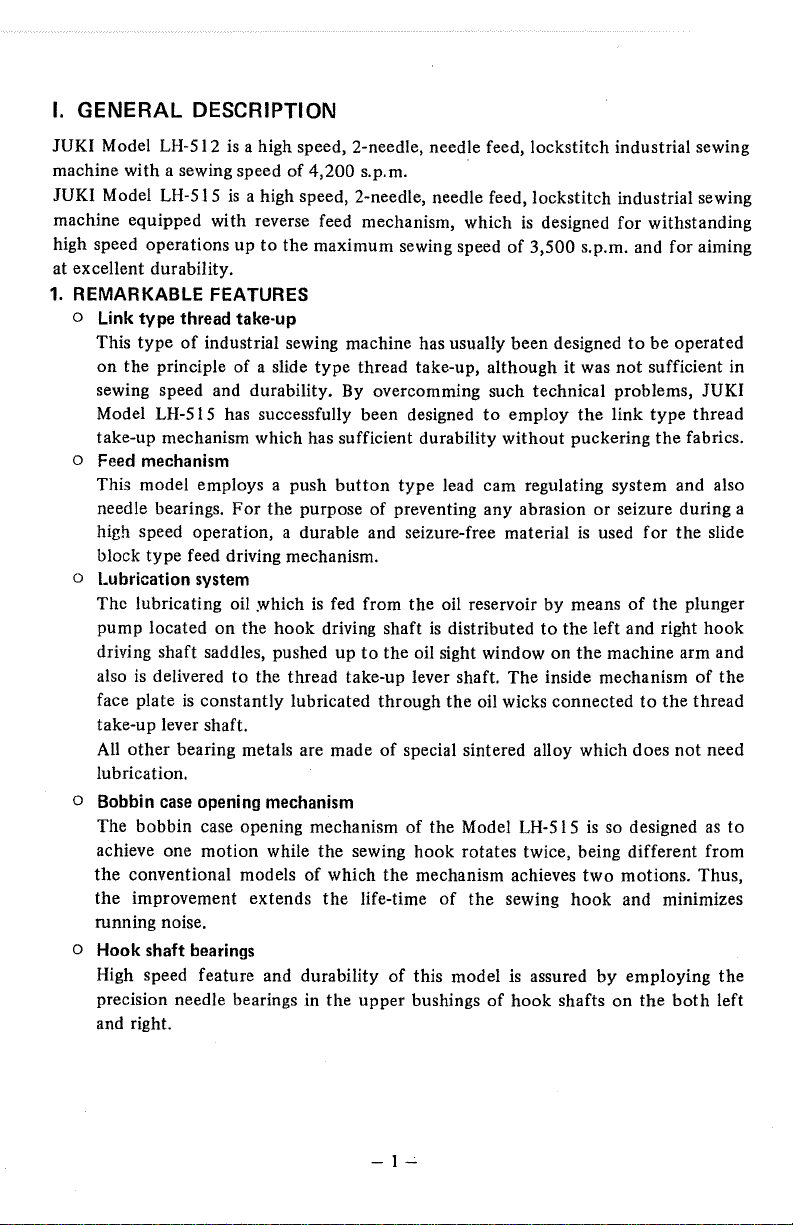
JUKI Model LH-512
machine with a sewing speed
JUKI Model LH-515
machine equipped with reverse feed mechanism, which
high speed operations
at excellent durability.
1.
REMARKABLE FEATURES
is
a high speed, 2-needle, needle feed, lockstitch industrial sewing
of
4,200
s.p.m.
is
a high speed, 2-needle, needle feed, lockstitch industrial sewing
is
designed for withstanding
up
to
the
maximum sewing speed
of
3,500
s.p.m. and for aiming
o Link type thread take·up
This
type
of
industrial sewing machine has usually been designed
on
the
principle of a slide
sewing speed and durability. By overcomming such technical problems,
Model LH-515 has successfully been designed
take-up mechanism which has sufficient durability
type
thread take-up, although it was
to
employ
without
the
puckering
o Feed mechanism
This model employs a push
For
needle bearings.
high speed operation, a durable and seizure-free material is used
block
type
feed driving mechanism.
the
button
purpose
type
lead cam regulating system and also
of
preventing any abrasion
o Lubrication system
The lubricating oil y.rhich
pump
located on
driving shaft saddles, pushed
also
is
delivered
face plate
take-up lever shaft.
All
other
bearing metals are made
lubrication.
to
is
constantly
the
is
fed from
hook
driving shaft
up
the
thread take-up lever shaft.
lubricated through
the
to
the
oil sight window
of
special sintered alloy which does
oil reservoir by means
is
distributed
the
oil wicks connected
to
the
on
the
The
inside mechanism
o Bobbin case opening mechanism
The
bobbin
achieve one
the
conventional models
the
improvement extends
running noise.
case opening mechanism
motion
while
of
the
which
the
sewing
the
life-time
of
the
Model LH-515
hook
rotates twice, being different from
mechanism achieves
of
the
sewing
is
two
hook
o Hook shaft bearings
High speed feature and durability
precision needle bearings in
and right.
the
of
upper
this model
bushings
of
is
assured
hook
shafts
to
be operated
not
sufficient in
JUKI
link
type
thread
the
fabrics.
or
seizure during a
for
the
of
the
plunger
left and right
machine arm and
to
so designed as
motions. Thus,
and minimizes
by
employing
on
the
the
not
both
hook
of
thread
slide
the
need
to
the
left
-1-'-
2.
SPECIFICATIONS
LH·515
Sewing
type
.......................... 2-needle, lockstitch, needle feed, with reverse feed
(by
mechanism
feed control lever).
Application ........................... Light and medium heavy weight materials. (Men's
shirts cuffs, front flies, attaching pockets
uniforms, felling trousers, attaching tapes
to
working
to
materials and sewing side face and waist inside
men's jackets, etc.)
Sewing speed ......................... Max.
Thread take-up ...................... Link
Needle bar stroke ..................
Needles .................................
Presser lifting amount ...........
3,500 s.p.m.
type
thread take-up
33.4mm
DP
DP
( 1-5/ 16")
x 7, No.I I,
x 5, No.I I,
7mm(9/32")
No.l4,
No.l4,
No.l6
No.l6
or
by hand lifter, 10mm(25/64")
by
lifter.
Feed mechanism ...................
Stitch length ......................... Max.
Stitch
length regulator .......... Feed eccentric adjustment system (by push
Needle gauge .........................
Bottom
4mm(5/32")
11
3/32
, 1/8
3/8",
l/2",
1-3/8",
feed and needle feed.
11
11
,5/32
,
3/16",
5/8",
3/4",
7/8",
1-l/2''
7/32",
I",
1/4",
1-l/8",
button).
9/32",
l-l/4",
Sewing hook ........................ Horizontally arranged automatic lubricating hooks for
high speed operation.
Lubrication system .............. Automatic lubricating system
by
means
of
pump and lead pump.
Driving
Table .................................. Table for model
motor
...................... 3-phase 400W
0/2HP)
LH-5
clutch mtor.
l 5
tricot
of
knee
5/16",
plunger
LH-512
Sewing type ........................ 2-needle, needle feed, lock stitch
Sewing speed .......................
other
(All
specifications are same
Up
to
4,200
as
LH-515)
s.p.m.
-2-
II.
INSTALLATION AND OPERATION
1.
INSTALLATION
The
following procedure will simplify
(1) Hinges
First
of
all,
you
must fix
the
accessory
Make suitable recessions on
width
their
positions
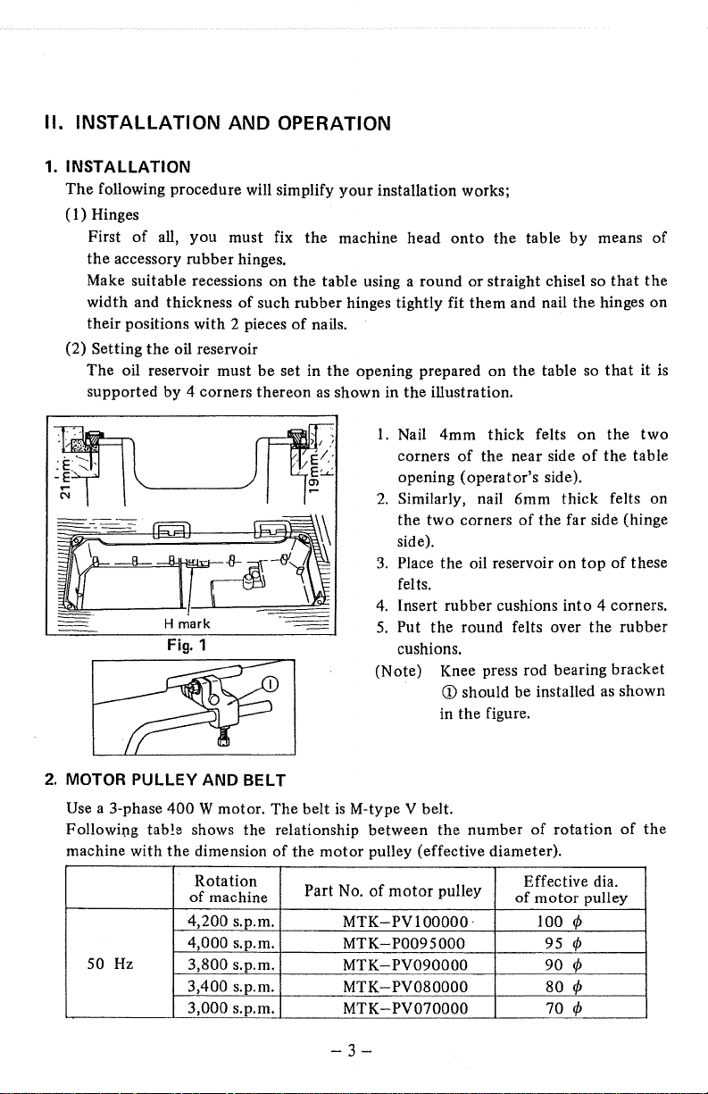
(2) Setting
The oil reservoir must
supported by 4 corners
---
rubber
and thickness
with
the
oil reservoir
hinges.
of
such
2 pieces
be
thereon
~
set
~~F~
~
Hmark
Fig.
-~
1
your
installation works;
the
machine head
the
table using a round
rubber
hinges tightly fit
of
nails.
in
the
opening prepared on
as
shown in
1.
2.
3.
4.
5.
(Note) Knee press rod bearing
the
Nail
corners
opening
Similarly, nail
the
side).
Place
felts.
Insert rubber cushions
Put
cushions.
onto
the
table
or
straight chisel so
them
and nail
the
illustration.
4mm
thick felts
of
the
near side
(operator's
6mm
two
corners
the
the
round felts over
CD
should be installed as
in
the
of
oil reservoir on
figure.
by
means
the
hinges on
table so
on
of
side).
thick
the
far side (hinge
top
into
4 corners.
the
that
the
that
it
the
two
the
table
felts on
of
these
rubber
bracket
shown
of
is
~I
2.
MOTOR PULLEY AND BELT
Use a 3-phase
Following tab!e shows the relationship between
machine
50
Hz
with
400
W motor. The belt
the
dimension
Rotation
of
machine
4,200 s.p.m.
4,000 s.p.m.
3,800 s.p.m.
3,400 s.p.m.
3,000
s.p.m.
of
is
M-type V belt.
the
motor
Part No.
MTKMTK-P0095000
MTK-PV090000
MTK-PV080000
MTK-PV070000
-3-
the
number
pulley (effective diameter).
of
motor
pulley
PV 1
00000
· 100
of
Effective dia.
of
motor
95
90
80
70
rotation
pulley
rp
rp
rp
rp
rp
of
the
Rotation
of
machine
4,200
s.p.m.
4,
000
s.
p.m.
60Hz
(Note)
3.
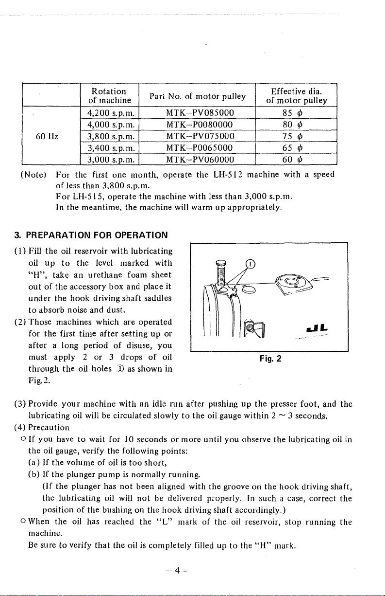
PREPARATION
(I)
(2)
For
of
For
In the meantime, the machine will warm
Fill the oil reservoir with lubricating
oil
up
"H",
take
out
of
the accessory box and place
under
the
to
absorb noise and dust.
Those machines which are
for the first time
after
a long period
must apply 2
through
Fig.2.
3,800
s.p.m.
3,400 s.p.m.
3,000
s.p.m.
the first one
less than
LH-515, operate
to
hook
the oil holes
3,800
FOR
the level marked
an
urethane
driving
after
or 3 drops
month,
s.p.m.
OPERATION
foam sheet
shaft
setting
of
disuse,
j)
as shown in
Part
No. of
motor
MTK-PV085000
MTK-P0080000
MTK-PV075000
MTK-P0065000
MTK-
PV060000
operate
the
machine with less than
with
it
saddles
operated
up
or
you
of
oil
the
3,000
Fig.
Effective dia.
of
motor
pulley
85 ¢
80 ¢
¢
75
¢
65
¢
60
s.p.m.
2
pulley
LH-512 machine with a speed
up
appropriately.
(3)
Provide
lubricating oil will be circulated slowly
(4)
Precaution
o If
the oil gauge, verify the following points:
(a)
(b)
o When the oil has reached the
machine.
Be
your
machine with
you
have
to
If
the volume
If
the
plunger
(If
the plunger has
the
lubricating oil will
position
sure
to
of
verify
an
idle
wait for 10 seconds
of
oil
is
too
short,
pump
is
normally running.
not
been aligned with the groove on the
not
be delivered pl·operly. In such a case, correct the
the bushing on the
"L"
that
the oil is completely filled
run
after
pushing
to
the
oil gauge
or
more until
hook
driving shaft accordingly.)
mark
of
you
the
oil reservoir,
up
to
up
the
within
observe
the
"H"
presser
2 ~ 3 seconds.
foot,
the
lubricating oil in
hook
driving shaft,
stop
running the
mark.
and
the
-4-
Ill.
HOW TO OPERATE THE MACHINE
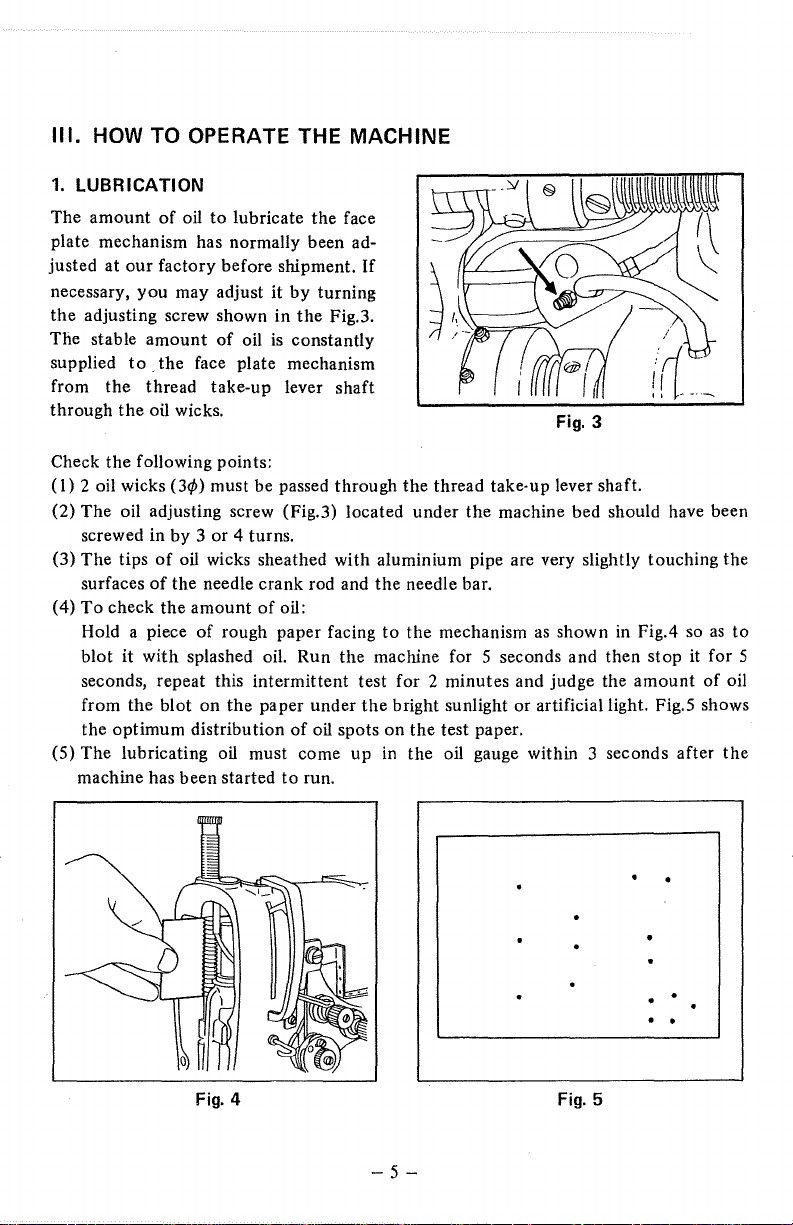
1.
LUBRICATION
The
amount
plate mechanism has normally been ad-
justed at
necessary, you may adjust it
the
adjusting screw shown in
The stable
supplied
from
through
Check the following points:
(I)
2 oil wicks
The
(2)
screwed in
(3)
The
surfaces
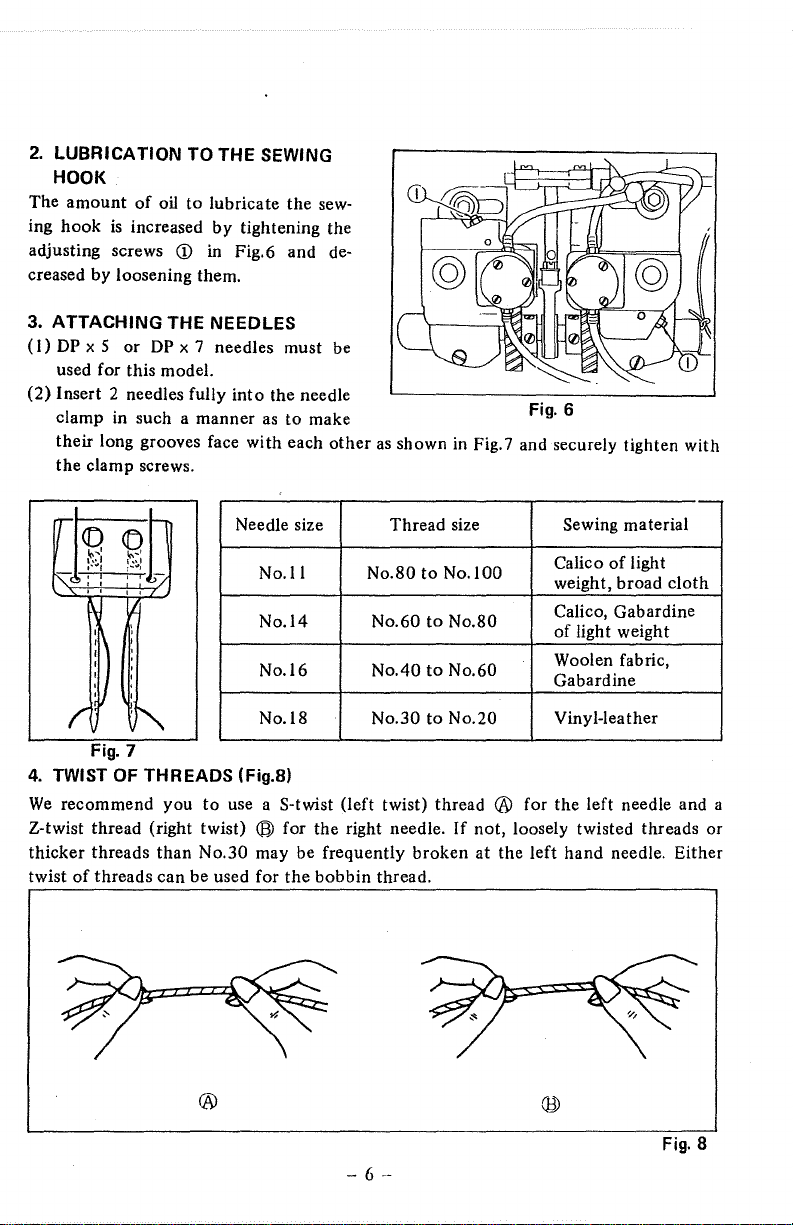
(4)
To
Hold a piece of rough paper facing
blot
seconds, repeat this intermittent test for 2 minutes and judge the amount of oil
from the blot on
the optimum distribution
(5) The lubricating oil must come up in the oil gauge within 3 seconds after
machine has been started
of
oil
to
lubricate
our
factory before shipment.
amount
to
. the face plate mechanism
the
thread take-up lever shaft
the
oil wicks.
oil adjusting screw (Fig.3) located under the machine bed should have been
tips
of
of
check the amount
it
with
of
oil
(3c/>)
must be passed through
by
3 or 4 turns.
oil wicks sheathed with aluminium pipe are very slightly touching the
the needle crank rod and
splashed
the
the
face
If
by
turning
the
Fig.3.
is
constantly
Fig.
3
the
thread take-up lever shaft.
the
needle bar.
of
oil:
to
the mechanism
oiL
Run the machine for 5 seconds and then stop it for 5
paper under
of
to
the
bright sunlight or artificial light. Fig.5 shows
oil spots on the test paper.
run.
as
shown
in
Fig.4 so
as
to
the
• •
Fig.
4
Fig.
5
-5-
2.
LUBRICATION TO THE SEWING
HOOK
The
amount
ing
hook
adjusting screws
of
is
increased
oil
to
<D
lubricate
by
in
tightening the
Fig.6 and de-
creased by loosening them.
ATTACHING THE NEEDLES
3.
(I)
DP
x 5
or
DP
x 7 needles must be
used for this model.
(2) Insert 2 needles fully
clamp in such a manner
into
as
their long grooves face with each
the
clamp screws.
rT
<f)
<D
...
I
"''I
,,.J
i•"
,~
...
,
:
.....
,
)/
: I
'
'
!'C
Y.
: H
I I :
I '
I 1
I
I
I
Fig.
of
threads
·~
7
than
can
r
4.
TWIST OF THREADS (Fig.8)
We
recommend you
Z-twist thread (right twist)
thicker threads
twist
Needle size Thread size
No.I I
No.l4
No.16
No.l8
to
use a S-twist (left twist) thread ® for the left needle and a
® for the right needle. If not, loosely twisted threads or
No.30 may be frequently broken
be used for
the
sew-
the needle
to make
other
the
bobbin thread.
as
shown
No.80
No.60
No.40
No.30
in
Fig. 7 and securely tighten with
Sewing material
to
No.lOO
to
No.80
to
No.60
to
No.20
at
Calico
weight, broad
Calico, Gabardine
of
light weight
Woolen fabric,
Gabardine
Vinyl-leather
the left hand needle. Either
of
--
light
cloth
®
Fig.
8
- 6
--

5.
PASSING THE NEEDLE THREADS
Pass the needle thread in the order shown in Fig.9.
The needle thread
operators' side) must be passed in the order
thread take-up lever upper hole
in the order
-+
hole
right needle).
to
of ® to
be passed through
-+left
the
of
needle). The right
® (Right thread tension disc
left hand needle (seeing from the
<D
to
® (Left thread tension disc
hand
needle
must
be passed
-+
thread take-up lever lower
-+
Fig. 9
-7-

6.
PASSING THE BOBBIN THREAD
When
you
pull
out
the
bobbin
through the bobbin case holder, verify
that
the thread
notched
shown
7.
(1)
(2) Bobbin thread tension.
part
in
Fig.l
ADJUSTING THE THREAD
TENSION
Needle thread tension.
For
obtaining optimum needle thread
tension, turn the thread tension post
nut
<D
needle thread and
left
hand needle thread. The thread tension will be increased by clockwise turn and
decreased by counterclockwise turn.
For
adjusting the bobbin thread tension, turn the adjusting screws
the
left and right bobbin case holders. Clockwise
clockwise
is
passed through the
<D
of
thereof
0.
Fig.ll
turn
without
for the right hand
the
nut
decreased the bobbin thread tension.
thread
fail,
as
® for the
Fig.
10
<D
turn
increases and counter-
of
Fig.l2
on
Fig.
11
- 8 --
Fig.11

(3) Tension
For
spring stud
by
tension post
ahout
of
thread take-up spring.
adjusting
the
tension
(['
of
Fig.l3. The tension
of
the thread take-up spring,
counterclockwise turn. After adjustment, lock
nut ® of
20
g.
and the stroke
Fig.l3.
is
Normally, the tension
7mm(9/32")
light fabric or a synthetic fiber material,
increase it's stroke.
To
change the stroke
and slide the stopper ®
Fig.
13
of
the thread take-up spring, loosen the screw
to
the right for increasing and
is
increased
to
you
turn
the thread take-up
by
clockwise
it
of
the thread take-up spring
10mm(i3/32
turn
and decreased
by
tightening
11
).
When you sew a very
the
thread
must lessen the spring tension and
<D
of
Fig.l4
to
the left for decreasing.
Fig.
14
is
-9-

8.
ADJUSTING THE STITCH LENGTH (Fig.15)
As
you
keep on pressing
wheel
® manually. When
stitch length, which is indicated
pointer®
down
the
button
the
·button·is engaged with a groove, adjust a desirable
by
CD
the
graduations
Kl
on
the machine bed, rotate the hand
on
the handwheel,
!
to
the
Fig.15
9.
REVERSE FEED (LH-515)
To
produce
limited by the stopper. The reverse feed is
the
reverse stitches, press down the feed lever
kept
as long
Fig.
CD
as
you press it.
16
Fig.l6
fully until
it
is
-10-

IV. HOW TO ADJUST THE MACHINE
1.
TIMING
When the
bottom
bar has gone
engraved marks located od the pivot
with each
OF
upper
surface
up
other
THE BOBBIN
line engraved
of
the needle bar frame ( ® of
by 0.2 ~ 0.3mm(l/l28" ~ 3/256")
as
shown in Fig.l8.
CASE
OPENING MECHANISM
on
the needle
of
the bobbin case opening lever link must aligned
bar
(CD
Fig.l7),
from
of
Fig.l7)
in other word, when the needle
it's
coincides with the
bottom
dead point,
two
Fig. 17
2.
ADJUSTING THE BOBBIN
Adjust the position
bobbin case holder allowing the thread
of
such thread
surface
of
throat
( ® of Fig.20),
careful
may make a high noise and shorten
not
to
of
the bobbin case opening lever
at
the moment when
plate
as
obtain
a correct position and finally tighten
allow it
Fig.
to
19
CASE
OPENING MECHANISM
the
shown in
open the bobbin case holder
Fig.l9.
it's
Fig.18
(CD
of
Fig.20) so
to
pass through depending
needle thread
To adjust the said lever, loosen
lifetime.
-
11-
is
pulled
the
too
much, or the sewing
Fig.
as
to
open the
upon
the thickness
up
along
the
bottom
the
screw
screw. You must be
hook
20

3.
MOVEMENT
OF
THE NEEDLE AND THE SEWING HOOK
(1 I Timing
Set
o When the needle has gone
0 When
o The
of the needle
the
feed
amount
timing
of
the needle and
the
points
their needles,
0.05mm
of
2mm
as shown in Fig.21B.
hook
point must point
needle eye as shown in Fig.21A.
Fig.
and
the sewing hook (Fig.21A &
to
2mm(5/64"),
the
of
left and right sewing hooks coincide
the
clearance between each
21A
up
sewing
at
a higher level
(Note)
The upper engraved marking line on
surface
The lower engraved line
of
the
needle
bar
frame, when
thereon
will coincide with the
when the needle bar has gone up by
2mm(S/64
and remove
2mm(5/64
hook
the
needle
the
needle bar
the
11
) from it's
is
as shown
hook
by
0.05mm
bar
is
11
) from it's
21
B)
throat
plate.
bottom
in
Fig.
point and
1.2mm(3/64
Fig.
21
with
11
218
dead point,
A.
the
center
the
needle face
)
than
the
will coincide with the
at
the
bottom
bottom
bottom
dead point.
surface
of
dead point.
lines
top
bottom
the
the
of
is
edge
frame,
-12-

(2) Matching
hook
Loosen
the
small gear which drives
driving shaft (small) and adjust
of
ing
In
order
ness,
the
said screw
push down
gear at
4.
ADJUST THE CLEARANCE BETWEEN THE NEEDLE
(Fig.23)
Adjust
way:
(a)
Remove
(b) Tilt
(c)
Loosen 3 screws which fix a
saddle; A', B' screws are for
(d)
Tap
(e)
Tighten
the
timing
of
the
set screw ( Q)
sewing hook.
to
eliminate any vertical loose-
after
adjustment,
with
the
the
same time.
the
clearance
the
the
machine head backwards.
the
hook
the
you
such a
hook
and
by
presser foot and the
driving shaft saddle gently
screws A(A') and B(B') and finally fix
the
sewing
of
Fig.22) on
the
the
must tighten
manner
to
pull
up
correcting
hook
the
hook
tim-
as
to
the
the
sewing
throat
driving shaft saddle (A, B screws
left saddle.)
plate.
to
correct
hook
AND
THE HOOK POINT
position according
it's
position.
the
saddle.
are
to
following
for
the
right
A
Fig. 23
-13-

5.
DETACHING
THE SEWING HOOK
(1) Detaching the sewing hook.
(a)
Open the bed slide
(b) Bring up
remove
the
AND
ATTACHING
..
the
presser foot and
throat
plate.
(c) Loosen 2 hexagon socket head
screws
(CD
of
Fig.24), which fix
a sewing
by
hook
to
it's driving shaft,
using a hexagonal spanner
stored in the accessory box.
at
it's
(d) Bring up the needle
dead point
the
handwheel and take out
by
manually rotating
top
the
sewing hook upwards.
(2) Attaching the sewing hook
(a)
Reverse the procedures mentioned in
(b) Before attaching the
that
the protruding part thereof agrees with the groove on the
6.
ADJUSTING THE HEIGHT OF
THE FEED
DOG
The standard height
measuring from the
throat plate
in
Fig.25. Adjust it,
is
0.8mm(l/32"),
throat
of
the
top
surface
if
necessary, by
plate, manually rotate the bobbin case holder so
feed dog
of
the
as
shown
loosening 2 screws which set the feed
dog.
(1
Fig.
24
).
throat
plate.
Fig.
25
-
14-

7.
ADJUSTING THE NEEDLE BAR
FRAME
The
correct clearance between
surfaces
ser
bottom
ing when
to
The correctly adjusted feed movement
constantly follows
center
For
( ®
needle bar so
dog and re-tighten the clamp screw.
If
clamp screw
screw
screw
the
holes on the feed dog as mentioned before.
of
the needle bar and the pres-
foot
is
14mm(35/64")
surface
Omm,
of
adjusting
of
Fig.27) on
the rock shaft driving
(CD
(CD
presser bar becomes
of
the
presser bar bush-
the
stitch length has been set
as
illustrated in Fig.26
up
the
the needle hole on the feed dog.
the
longitudinal position
the
needle bar rock shaft driving rod crank
that
the needles are pointed
(CD
of
Fig.28)
of
Fig.27), pull the driving rod crank fully towards you, re-tighten
of
Fig.28) at the point where
the
measuring
movement
rod
( ®
on
the
16.
5mm(21/32"),
outer
of
of
of
Fig.27) hits
rock shaft driving arm (rear) before tightening the
is
proved by the motion
the feed dog and
the
needle
bar
frame, loosen
at
the
center
of
the
the
surface
the
said clearance between
and finally align
the
Fig.
26
of
the
needle which
is
always pointing at
the
clamp screw
(CD
of
Fig.27), adjust the
needle hole
of
the arm, loosen the
needles with
on
the
needle bar and
the
the
the
clamp
needle
the
feed
Fig.
27
-IS-
Fig.
28

8.
ADJUSTING THE MAXIMUM STITCH LENGTH(LH-515)
When
you can
position of the feed limiting plate (
machine bed.
If the maximum stitch length
backwards, loosen 2 screws (
plate upwards.
downwards and re-tighten the screws firmly. After adjustment you must measure the
maximum stitch length for the distance
stitches on a piece
The maximum stitch length
of
the feed limiting plate using the adjusting screw
(@
of
Fig.29) and turn the screw clockwise for increasing the stitch length or counter-
clockwise for decreasing.
9.
REPLACING THE TIMING BELT
Firstly, you must remove
feed control lever shaft. Tilt
head backwards and loosen 2 screws
which set the arm
shaft. And remove the end screw which
is
located on
feed lever and take
shaft as they are assembled together
the
from
right hand side.
(l)
Disengage the timing belt from
sprocket wheels.
(2) Take
with the built-in bearing.
Pull
(3)
opening made by
belt for replacement with care not
give
not
get the maximum stitch length, you can adjust it
of
®
of
If
the
stitch length is
of
paper.
of
the reverse feed can be adjusted by changing the height
the
the
machine
to
the
control lever
the
opposite side
out
the
lever and
machine head towards the
out
the
handwheel together
out
the timing belt from the
® and insert new
any sharp
bentto
the
new belt.
by
changing the
d)
of
Fig.29) located on the back side
the
normal feed
Fig.29) clamping the feed limiting plate and slip the
too
reverse
of
the
it's
the
to
is
not enough, tilt the machine head
long, on the contrary, slip the said plate
of
II
stitches by manually forming such
(@
of
Fig.29). Loosen the lock nut
Fig.
29
of
the
-
16-

10.
ADJUSTING THE POSITION OF THE TIMING BELT
After
replacing
position
shaft with each other.
Rotate
same level as
hook
wheel (
belt
on
the
driving shaft
®
at this position.
or
of
it so as
main shaft in
the
of
Fig.31)
Fig.
disengaging
to
match
the
top
surface
in
the
normal direction
is
aligned
30
the
timing belt from
the
movements
normal direction
of
the
throat
plate as shown
until
with
the
timing mark ( ®
of
until
the
sprockets,
the main shaft and
the
needle has
in
Fig.30, then,
the
first screw
of
on
Fig.3l)
Fig.
you
must adjust
the
come
the
and
31
hook
down
lower
put
driving
to
rotate
sprocket
the
timing
the
the
the
-17-

V.
HOW
TO OBTAIN THE IDEAL SEWING CONDITIONS
o STANDARD SEWING CONDITIONS
Thickness
of
thread
Sewing
material
Needle
Needle
thread
tension
Bobbin
thread 15 to
tension
Thread
take-up
tension
Thread
take-up
stroke
Sewing
speed.
(s.p.m.)
Tetoron
No.
Tetoron
broadcloth
2 sheets
DPx
No.I I
12mm 12mm
(15/32")
SO
7 DP X 7
20g
20g,
15g.
3,500
Nylon
No.60 No.
Tetoron
broadcloth gabardine gabardine
2 sheets 2 sheets 2 sheets 2 sheets
No.l4
25
to
30g. 45 to 50g. 50 to 60g. 80 to
15
to
20g. 25 to 30g.
15g. 25g.
(15/32")
3,500
Cotton Cotton
SO
Cotton Cotton
DPx
7
No.l4
lOmm lOmm 12mm
(25/64") (25/64") (15/32")
3,500 3,500 3,500
No.
SO
DPx
7
No.l4
25
to 30g. 30 to 40g.
25g.
Vinyl on
No.30
Vinylleather
DP
X 7
No.l8
lOOg.
30g.
-18-

o TROUBLES
AND
CORRECTIVE MEASURES
Trouble
A.
Thread breakage.
1.
Thread
is
or worn
2.
out
Needle thread
snapped remaining a length
to
3cm (about
1") on the bot-
tom
surface
sewing material.
ravelling
is
of
2
of
Cause
{1)
There are scratches
surface
of
thread paths,
pointed end
hook point or on the rear groove the throat plate groove.
of
the throat plate
the bobbin case holder.
(2) Needle thread tension
high.
(3) Bobbin case opening mecha-
nism actuates too much. bobbin case opening mechanism
(4) Needle contacts with the o Tap the hook driving shaft
sewing hook.
(5) Lubricating oil fed
sewing hook
{1)
Needle thread tension
low.
(2) Thread take-up spring has
high tension and small stroke.
(3)
Needles are attached incor- o The cross-section view of 2
rectly.
(especially synthetic fiber thread top.
is
used.)
of
is
on
the o
on
the
the needle, on the for the hook
to
positioning
is
too
to
too short.
the
is
too
Corrective measures
Make
those surfaces smooth by
of
to
111-7.
of
~
~
@
point
of
thread take-up
111-7-(3)).
as
a fine sand-paper
or a buff for
to
the sewing
sewing hook.
of
oil fed to
is
affected
20g. and bobbin
is
15g. in the case
viewed from their
~
§
@
making use
o Refer
"Adjusting the thread tension".
o Loosen the set screw on the
and bring it closer
hook. (see IV-2).
saddle gently to adjust the clearance between the needle and the
blade point
(see IV-4)
o Adjust the amount
the sewing hook. (see III-2).
o Synthetic fiber thread
significantly. Suitable needle
thread tension is
thread tension
of Synthetic fiber thread.
(see III-7).
o Decrease the tension and increase
the stroke
spring. (see
needle eyes
a.
Not good for synthetic fiber
thread.
b.
Standard.
c.
In some cases good for synthe-
tic fiber thread.
-
19-

Trouble
Cause
Corrective measures
B.
Skip-stitching.
(4) Motions
needle are
nized with each other. (see IV-3-(l)).
(5) Timing
motion
(l)
Clearance between the hook
point and needle
(2) Motions
the needle are not synchronized
correctly with each other.
(3)
Presser foot
(Pressing force
(4) Needles are positioned
incorrectly.
(5) Height of the needle bar
correct.
of
sewing hook and the o Adjust the timing between the
not
properly synchro- needle and the hook.
of
bobbin case opening o Adjust the timing
is
not
correct. opening motion. (see IV-1).
is
too much.
of
sewing hook and
is
not
functioning.
is
too small).
o Correct the clearance. (see IV-4)
o Correct their timing. (see IV-3-(1))
o Tighten the presser spring
regulatr.
is
not
~
o Correct their position.
(see above A-2-(3))
o Upper marking line on the needle
bar must coincide with the
bottom surface
frame when the bar
be:·,,~
of
bobbin
--~~
of
needle bar
is
at
the
1
C.
Irregular stitches.
(1) Bobbin thread
through the notched part of
tension spring on the bobbin
case.
Outer rim
(2)
smooth enough to rotate freely .
of
is
not
bobbin
....;_
20-
passed
is
not
~-l_\~E-..-,-ll...lt---
UJ
o
Pass
the bobbin thread through
the notched part. (see III-6).
o Replace the bobbin or polish it
with a fine sandpaper.

Trouble Cause
Corrective measures
1.
Irregular stitches
are f orrned
sewing speed varies.
D.
Puckering
sewing material
occurs very
frequently
as
of
(1)
Tension
the spring
(2) Bobbin case opening mechanism does
(3) Bobbin thread tension
low. (see III-7-(2)).
( 4) Surface
smooth.
(5) Sewing hook
the
(1)
tensions are too high.
(2) Bobbin thread
tight in the bobbin. again more softly
(This
synthetic fiber thread.)
(3) Pressing force applied by the o Loosen the presser spring
presser foot
( 4) Bottom surface
foot is
(5)
of
the thread take-up
is
too low. (see
not
work timingly.
is
of
thread paths is
is
faulty.
Both needle and bobbin thread
is
wound too o Take out the bobbin and wind
is
usually happened in the
is
too
strong. regulator. (see the above B-(3)).
of
presser
not
smooth.
Level
of
feed dog is too low.
o Correct the tension.
Ill·
7·(3)).
o Adjust the timing. (see IV-1).
too o Tighten the tension spring.
not
o Polish such surface with a fine
sandpaper.
o Replace
o Correct such thread tension.
(see III-
7).
the thread tension regulator (A).
.
~
it
o Make
o Adjust
smooth by making use
a fine sandpaper.
it
level. But,
0.15mm on it's way back
about
measuring
of
throat plate.
it
with new sewing hook.
by
loosening
~
to
a little more high
it
must be lowered by
froll] the top surface
it
of
E.
Needle thread
hops up and
down during
sewing.
(1)
Bobbin case opening mecha- o Correct the timing
not
nism does
(2) Tension
spring is too low. (see III-7-(3)).
function timingly. case opening mechanism
the bobbin thread
pulled
out
of the bobbin.
(see IV-I and 2.)
of
thread take-up o Increase the tension.
of
bobbin
is
regularly
so
that
-21-

To mder
()(
a.IUI<I
JUKI
CORPORATION
HEAD OFFICE
8·2·
i KOKURYO-CHO.
CHOFU-CITY,
BUSINESS OFFICE
1·23·3
SHINJUKU-KU,
PHONE: 03(3205)1188.
FAX:
TELEX:
TOKYO
182, JAPAN
KABUKI-CHO
TOKYO
160. JAPAN
03t3203)8260. (3205)9131
J22967.
1189,
232-2301
1190
Please
*The
*This
for further information, please contact :
do
not hesitate
to
description coVered in this instruction manual is subject
commodity without notioo.
instruction manual is edited and printed in accordance with the product specifications as of
September,
contact our distributors
1991.
or
agents in your area
lor
further informations when necessary.
to
change for improvement
of
the
 Loading...