


ENGLISH
INSTRUCTION MANUAL

CONTENTS
1. SPECIFICATIONS ............................................................................................................ 1
2. NAME OF EACH COMPONENT .....................................................................................3
3. INSTALLATION ................................................................................................................ 4
3-1. Caution at the time of set-up ................................................................................................................................ 4
3-2. Installation of the sewing machine ...................................................................................................................... 5
3-3. Adjusting the height of the knee lifter ................................................................................................................. 7
3-4. Installation of thread stand ................................................................................................................................... 7
4. PREPARATION OF THE SEWING MACHINE ................................................................ 8
4-1. Method of lubrication ............................................................................................................................................ 8
4-2. Lubrication to the oil tank ..................................................................................................................................... 9
4-3. Draining of oil from the oil tank ......................................................................................................................... 10
4-4. Adjusting the amount of oil in the hook ............................................................................................................ 10
4-5. Oil in the feed box ............................................................................................................................................... 12
4-6. Applying grease ................................................................................................................................................... 13
4-7. Installing the belt cover and the bobbin thread winder ................................................................................... 16
4-8. Attaching the needles .........................................................................................................................................16
4-9. How to take out the bobbin case ....................................................................................................................... 17
4-10. Insertlng a bobbin in a bobbin case ................................................................................................................17
4-11. Threading the machine head ............................................................................................................................ 18
4-12. Thread tension ................................................................................................................................................... 19
4-13. Thread take-up spring ....................................................................................................................................... 20
4-14. Adjusting the stitch length ...............................................................................................................................21
4-15. Needle-to-hook relation .................................................................................................................................... 21
4-16. Adjusting the needle stop position .................................................................................................................. 23
4-17. Pedal pressure and pedal stroke ..................................................................................................................... 24
4-18. Adjustment of the pedal .................................................................................................................................... 24
5. OPERATION OF THE SEWING MACHINE ..................................................................25
5-1. Pedal Operation ................................................................................................................................................... 25
5-2. Hand lifter ............................................................................................................................................................. 25
5-3. Adjusting the pressure of the presser foot ....................................................................................................... 26
5-4. Micro-lifter ............................................................................................................................................................ 26
5-5. Thread tension release changeover when using the knee lifter ..................................................................... 27
5-6. One-touch manual reverse feed (One-touch reverse feed type) ..................................................................... 27
6. MAINTENANCE ............................................................................................................. 28
6-1. Changing procedure to bottom feed and the adjustment (for LH-3528 only) ................................................ 28
6-2. Changing procedure to needle feed and the adjustment (for LH-3528 only) ................................................. 29
6-3. Adjusting the hook needle guard ....................................................................................................................... 30
6-4. Adjusting the inner hook guide .......................................................................................................................... 30
6-5. Adjusting the height and the inclination of the feed dog ................................................................................31
6-6. Replacing the gauge ........................................................................................................................................... 32
6-7. Adjusting the thread presser spring .................................................................................................................. 33
6-8. Adjusting the position of the moving knife ....................................................................................................... 34
6-9. Position of the wiper ...........................................................................................................................................35
6-10. Caution when installing the attachments ........................................................................................................ 35
6-11. Replacing the bobbin thread slack preventer sprlng (For LH-3568, 3568-7, 3588, 3588-7) ........................ 36
6-12. Stop of the needle bars and angle of corners for corners stitching (For LH-3568, 3568-7, 3588, 3588-7) 36
7. STITCH-TO-ANGLE TABLE BY GAUGE (PITCH AND mm CONVERSION TABLE) .. 37
8. GAUGE SETS ................................................................................................................ 38
9. TROUBLES AND CORRECTIVE MEASURES ............................................................. 45
10. MOTOR PULLEY AND BELT ...................................................................................... 46

1. SPECIFICATIONS
Model name LH-3528
Application
Hook Small hook Small hook
Thread trimmer Not provided Provided
Separately
driven needle bar
mechanism
Max. sewing speed
Needle DP x 5 #9 to #16 (For F,A and S types), DP x 5 #16 to #22 (G type)
Gauge size
Lift of presser foot 13 mm by knee lifter, 7 mm by hand lifter lever
Lubrication JUKI NEW DEFRIX OIL No. 1 or JUKI MACHINE OIL #7
Noise
S type : standard,F type : foundation, A type : light-weight materials, G type : jeans
Not provided Not provided
3/32" to 1-1/2" 1/8" to 1-1/4"
2.4 to 38.1 mm 3.2 to 31.8 mm
For light - and medium - weight materials
3,000 rpm
Workplace-related noise at sewing speed
n = 2,280 min–1 : Lpa ≦84 dB(A)
Noise measurement according to DIN 45635-48-A-1.
(with automatic thread trimmer)
LH-3528-7
Model name
Application
Hook Small hook Small hook
Thread trimmer Not provided Provided
Separately
driven needle bar
mechanism
Max. sewing speed
Needle DP x 5 #9 to #16 (S type), DP x 5 #16 to #22 (G type)
Gauge size
Lift of presser foot 13 mm by knee lifter, 7 mm by hand lifter lever
Lubrication JUKI NEW DEFRIX OIL No. 1 or JUKI MACHINE OIL #7
Noise
(with incorporating corner stitching)
LH-3568
For light- and medium-weight materials
S type : standard, G type : jeans
Provided Provided
3,000 rpm
1/8" to 3/4"
3.2 to 19.1 mm
Workplace-related noise at sewing speed
n = 2,140 min–1 : Lpa ≦84 dB(A)
Noise measurement according to DIN 45635-48-A-1.
(with automatic thread trimmer
incorporating corner stitching)
LH-3568-7
– 1 –

– 2 –
Model name LH-3578
(with automatic thread trimmer)
LH-3578-7
For medium - weight materials
Application
G type : jeans
Hook Large hook Large hook
Thread trimmer Not provided Provided
Separately
driven needle bar
Not provided Not provided
mechanism
Max. sewing speed
3,000 rpm
Needle DP x 5 #16 to #22 (G type)
3/16" to 1-1/12" 3/16" to 3/8"
Gauge size
4.8 to 38.1 mm 4.8 to 9.5 mm
Lift of presser foot 13 mm by knee lifter, 7 mm by hand lifter lever
Lubrication JUKI NEW DEFRIX OIL No. 1 or JUKI MACHINE OIL #7
Workplace-related noise at sewing speed
Noise
n = 1,800 min–1 : Lpa ≦84 dB(A)
Noise measurement according to DIN 45635-48-A-1.
LH-3588-7
Model name
LH-3588
(with incorporating corner stitching)
(with automatic thread trimmer
incorporating corner stitching)
For medium - weight materials
Application
G type : jeans
Hook Large hook Large hook
Thread trimmer Not provided Provided
Separately
driven needle bar
Provided Provided
mechanism
Max. sewing speed
3,000 rpm
Needle DP x 5 #16 to #22 (G type)
3/16" to 3/8"
Gauge size
4.8 to 9.5 mm
Lift of presser foot 13 mm by knee lifter, 7 mm by hand lifter lever
Lubrication JUKI NEW DEFRIX OIL No. 1 or JUKI MACHINE OIL #7
Workplace-related noise at sewing speed
Noise
n = 2,050 min–1 : Lpa ≦84 dB(A)
Noise measurement according to DIN 45635-48-A-1.
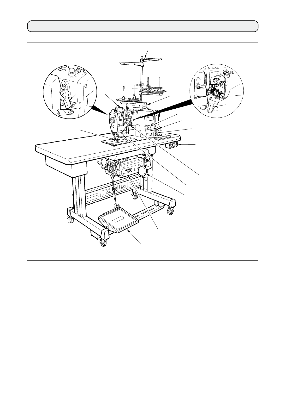
2. NAME OF EACH COMPONENT
!2
!5
3
2
!0
1
!3
!4
!1
8
4
9
7
5
Separately driven needle changeover lever
1
(LH-3568, 3568-7, 3588, 3588-7)
Thread take-up cover
2
Finger guard
3
Thread tension controller
4
Control box
5
Pedal
6
Knee padKnee pad
7
6
Power switch
8
Reverse feed switchReverse feed switch
9
Operation panel
!0
Bobbin winder
!1
Thread stand
!2
Oil supply opening
!3
Reverse feed control lever
!4
Hand lifter lever
!5
– 3 –
– 4 –
3. INSTALLATION
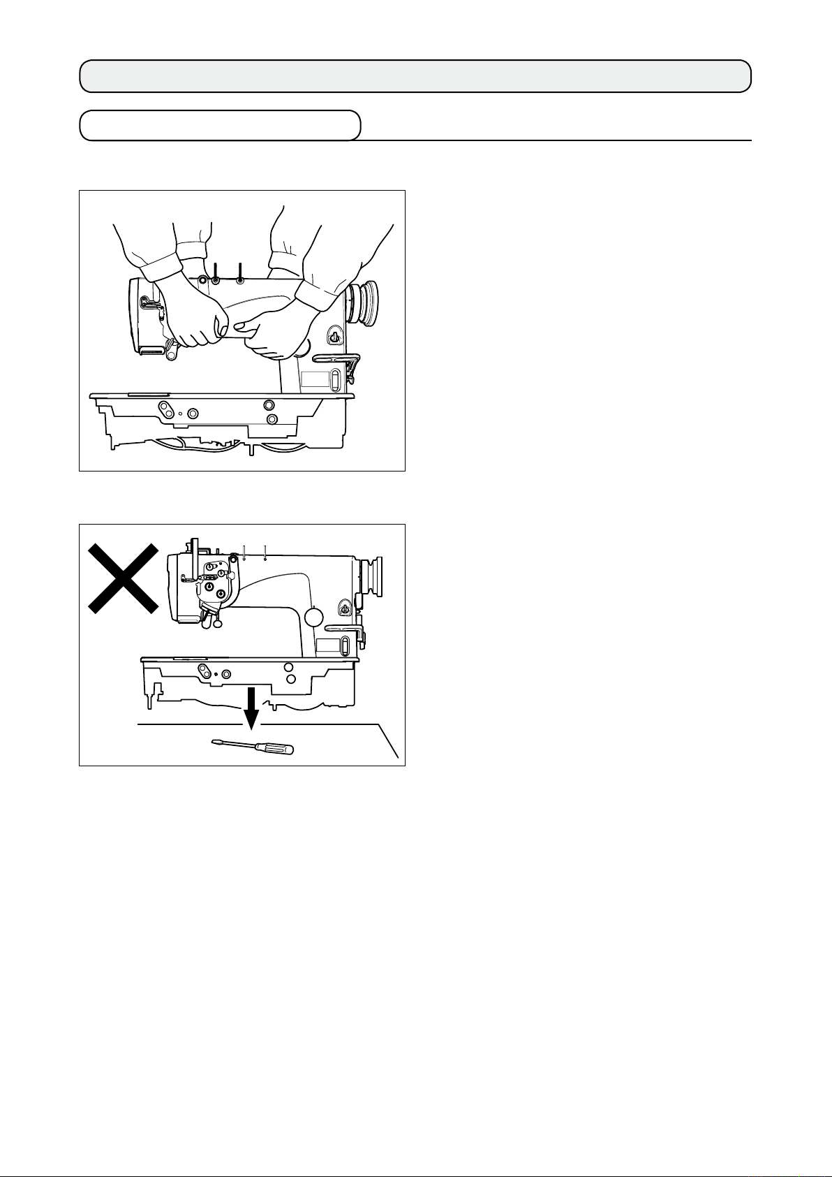
3-1. Caution at the time of set-up
1) Transporting procedure of the sewing machine
Hold and transport the sewing machine with two
persons as shown in the illustration.
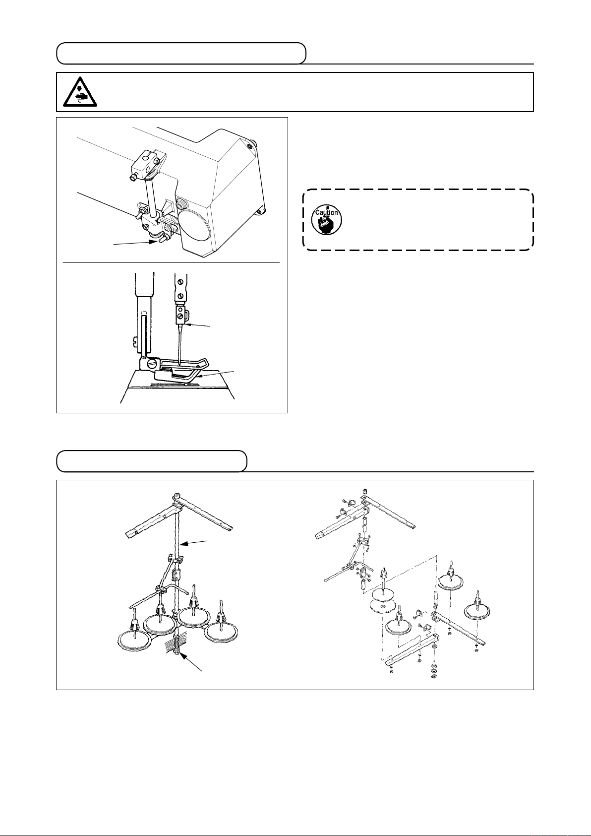
2) Caution when placing the sewing machine
Do not put protruding articles such as the
screwdriver and the like at the location where the
sewing machine is placed.
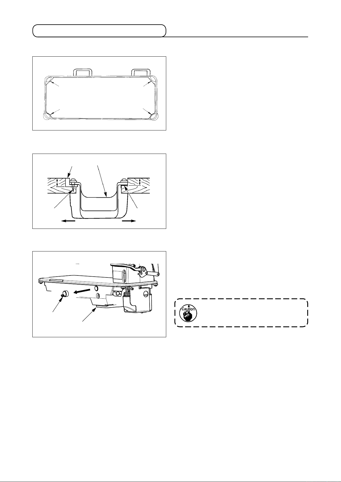
3-2. Installation of the sewing machine
(1) Installing the under cover
1) The under cover should rest on the four
corners of the machine table groove.
22.5 mm
2
3
1
1
A
4
B
3
1
18.5 mm
3
2) Fix two rubber seats 1 on side A (operator’
s side) using nails 2 as illustrated above. Fix
two cushion seats 3 on side B (hinged side)
using a rubber-based adhesive. Then place
under cover 4 on the xed seats.
5
C
3) Remove air vent cap 5 attached to the
machine bed. (Be sure to attach cap 5 when
transporting the machine head in the state
that the machine head is removed from the
machine table.)
If the sewing machine is operated without
removing air vent cap 5, oil leakage from
gear box portion C may occur.
– 5 –
– 6 –
8
7
6
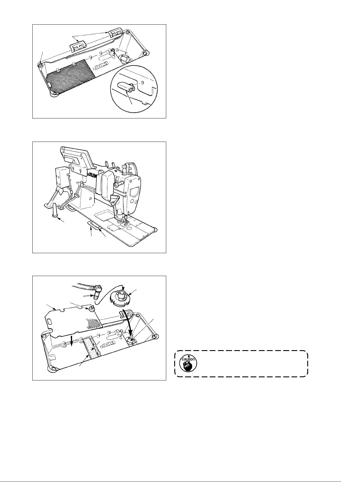
4) Insert hinge 6 into the machine main body.
Fit the machine head to table rubber hinges
and place it on head cushions 8 on the
7
four corners.
5) Attach head support rod 9 to the table.
!3
9
!4
!2
!0
7
E
6
!1
D
6) Remove inlet port !0 for circulation which
is xed to the oil tank installing plate, and
securely insert it into lter !1 until it goes
no further after removing cap !4 which is
attached to the end of the inlet port. Then set
the inlet port to D.
Place urethan lter !2 on E, and place lter
of thin plate type (small mesh plate) on it.
!3
Circulation trouble may occur unless inlet
port !0 for circulation is securely inserted
into ler !1 until it goes no further.
3-3. Adjusting the height of the knee lifter
WARNING :
To protect against possible personal injury due to abrupt start of the machine, be sure to start the
following work after turning the power off and ascertaining that the motor is at rest.
1
2
1) The standard height of the presser foot lifted
using the knee lifter is 12 mm.
2) You can adjust the presser foot lift up to 13
mm using knee lifter adjust screw 1.
Do not operate the sewing machine in the
state that the presser foot 3 is lifted by
12 mm or more since the needle bar 2
comes in contact with the presser foot 3.
3-4. Installation of thread stand
2
3
1
Assemble the thread stand, set it up on the machine table using the installation hole in the table and
tighten nut 1 gently.
When you use power supplied by the overhead power line, pass the power supply cord through hollow
spool rest rod 2.
– 7 –
– 8 –
4. PREPARATION OF THE SEWING MACHINE
4-1. Method of lubrication
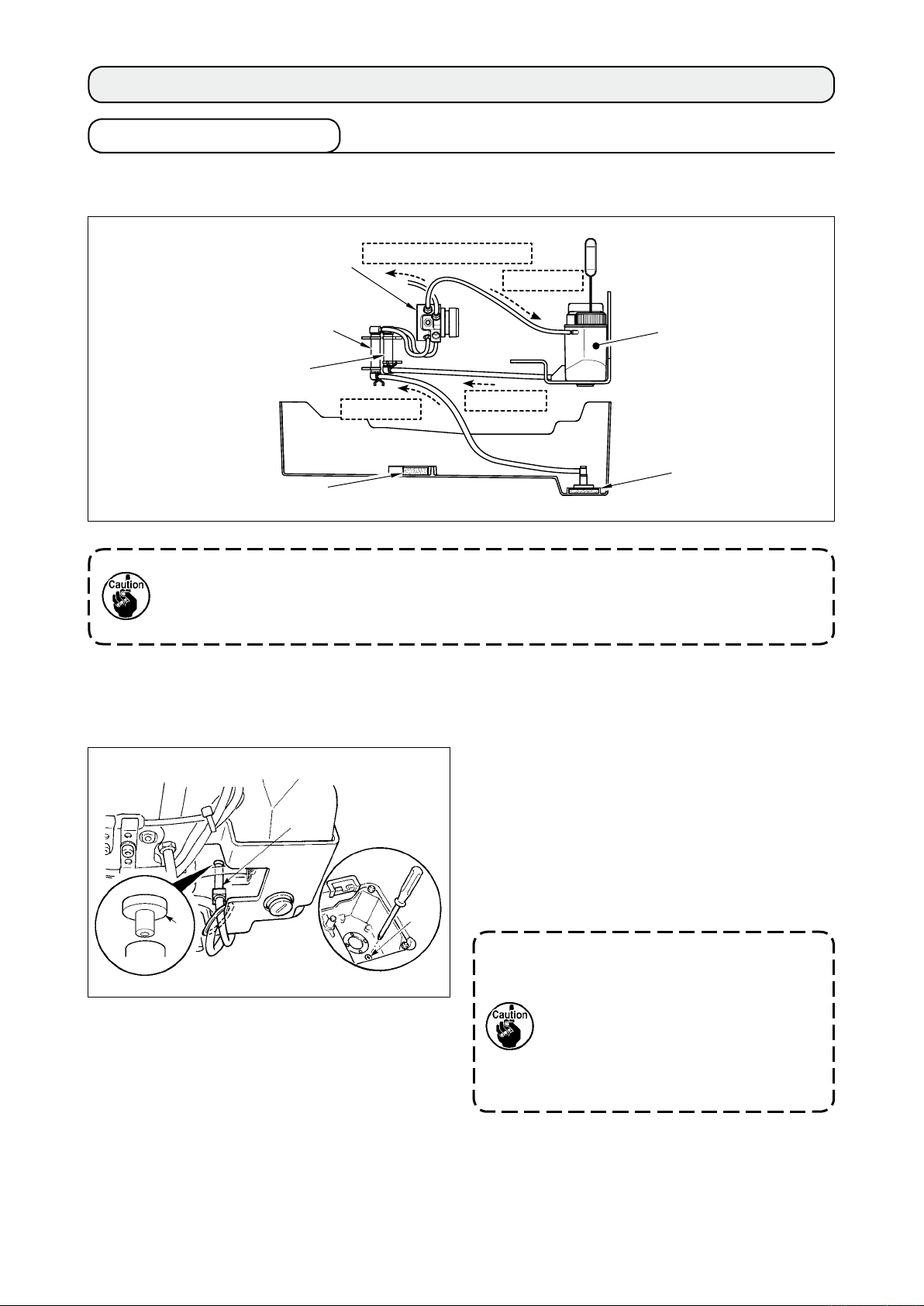
(1) Method of circulating lubrication (when the oil collected in the under cover is reused)
Plunger
Filter for plunger
Filter for plunger 2
Urethan lter
Periodically (approximately once in three months) clean the aforementioned lter sections (four
places) in order to use the machine for a long time. When the lter is clogged, lubrication trouble
will occur and break-down will be caused.
In addition, when the oil becomes dirty, replace the oil gathered in the oil tank and the under cover.
Lubrication to hook side
Circulation
Lubrication
Circulation
Oil tank
Filter for circulation
(2) Method of non-circulation type lubrication (when only the clean oil is always used)
Put cap 3 to inlet port for circulation 1 in the
same state as that at the time of delivery, and
securely x it to the position where it does not
1
come in contact with the moving section.
* Remove drain screw 2 and dump the oil
which has dropped to the under cover.
2
3
2
When inlet port for circulation 1 comes
in contact with the oil surface, oil is
absorbed without passing the lter. As a
result, break-down will be caused.
In addition, when cap 3 is not inserted,
oil leakage from inlet port for circulation
or unstableness of oil amount in the
1
hook may occur.
4-2. Lubrication to the oil tank
WARNING :
1. Do not connect the power plug until the lubrication has been completed so as to prevent
accidents due to abrupt start of the sewing machine,
2. To prevent the occurrence of an inammation or rash, immediately wash the related portions if
oil adheres to your eyes or other parts of your body.
3. If oil is mistakenly swallowed, diarrhea or vomitting may occur. Put oil in a place where children
cannot reach.
Lower
engraved
marker line
3
2
1
Upper
engraved
marker line
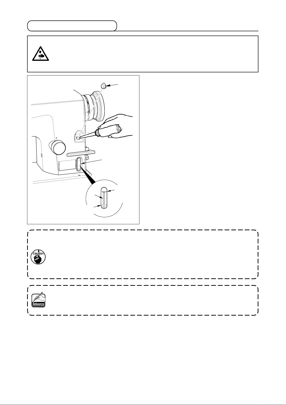
Fill the oil tank with oil for hook lubrication before
operating the sewing machine.
1) Remove oil hole cap 1 and ll the oil tank
with JUKI NEW DEFRIX OIL No.1 (Part No.
: MDFRX1600C0) or JUKI MACHINE OIL #7
(Part No. : MML007600CA) using the oiler
supplied with the machine.
2) Fill the oil tank with the oil until the top end of
oil amount indicating rod 3 comes between
the upper engraved marker line and the lower
engraved marker line of oil amount indicating
window 2.
If the oil is lled excessively, it will leak from
the air vent hole in the oil tank or proper
lubrication will be not performed. So, be
careful.
3) When you operate the sewing machine, rell
oil if the top end of oil amount indicating rod
comes down to the lower engraved marker
3
line of oil amount indicating window 2.
• When lling the oil tank with the oil initially, make sure that the oil amount indicating rod works.
When it does not work at this time, make it work by tilting the sewing machine once.
• When you use a new sewing machine or a sewing machine after an extended period of disuse, use
the sewing machine after performing break-in at 2,000 rpm or less.
• For the oil for hook lubrication, purchase JUKI NEW DEFRIX OIL No. 1 (Part No. : MDFRX1600C0)
or JUKI MACHINE OIL #7 (Part No. : MML007600CA).
• Be sure to lubricate clean oil.
In case of the circulation type lubrication method, when using the sewing machine for the rst time,
the oil amount in the oil tank decreases until the oil has collected in the ler for circulation. When
the top end of oil amount indicating rod is lower than the lower engraved marker line, add the oil to
the oil tank again so that the top end enters between the upper and lower engraved marker lines.
– 9 –
– 10 –
4-3. Draining of oil from the oil tank
WARNING :
1. To prevent accidents caused by abrupt start of the sewing machine, do not connect the power
plug until draining of oil has been completed.
2. To prevent the occurrence of an inammation or rash, immediately wash the related portions if
oil adheres to your eyes or other parts of your body.
3. If oil is mistakenly swallowed, diarrhea or vomitting may occur. Put oil in a place where children
cannot reach.
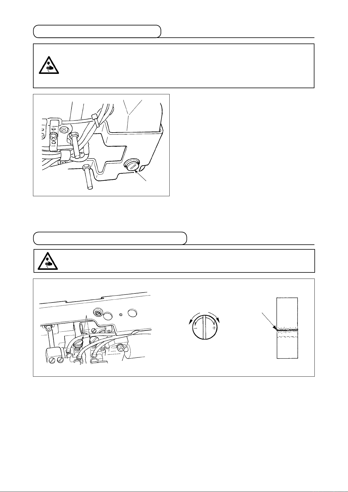
1
When draining oil from the oil tank, loosen drain
screw 1 with the L-shaped screwdriver (Part No.
: B9101490000) supplied as accessories and
remove it.
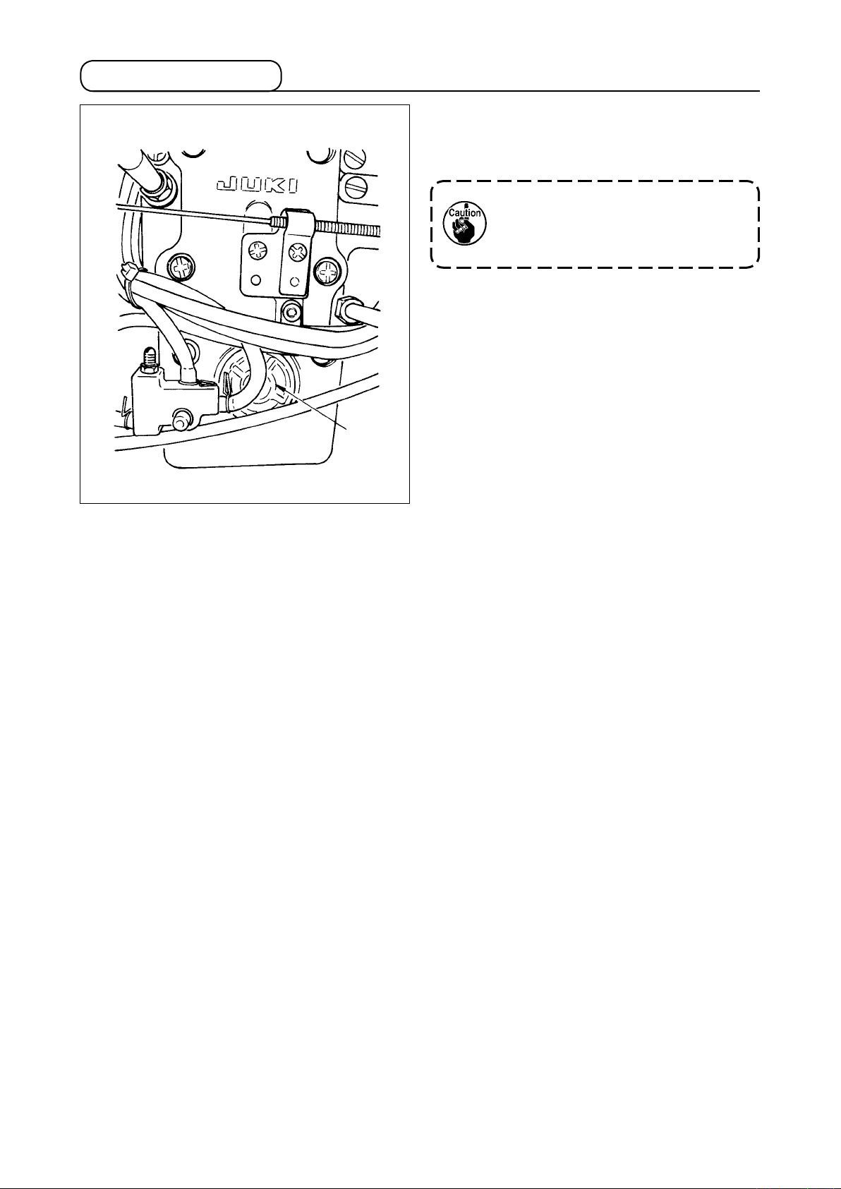
4-4. Adjusting the amount of oil in the hook
WARNING :
To protect against possible personal injury due to abrupt start of the machine, be sure to start the
following work after turning the power off and ascertaining that the motor is at rest.
1
Oil amount
decreases
Adjust the amount oil using adjusting screw 1. Turn screw 1 clockwise to increase the amount of oil
in the hook or counterclockwise to decrease it. Measure the amount of oil in ve seconds. When the
amount of oil is excessively decreased, break-down will be caused. So, be careful.
Oil splashes
Oil amo unt
increases

To use in safety, replace the oil wick of hook section with a new one approximately once a year with
the procedure below.
1
3
4
2
1) Loosen setscrews
(small hook : 2 places,
2
large hook : 3 places) and remove hook gib 1.
2) Remove inner hook
3) Loosen oil plug
4
.
3
with the L-shaped
screwdriver (Part No. : B9101490000) and
remove it.
4) Draw out oil wick
inserted into oil plug 4,
5
and replace it with a new one.
[Part No. of oil wick 5]
Small hook 11015906
Large hook 11404704
When strongly pressing oil wick 5, it may
be broken. Lightly insert it to such an
extent that it is not drawn out.
5
After the replacement, assemble oil plug 4,
inner hook 3 and hook gib 1 to the hook by
reversing the above procedure.
Perform conrming of oil splash.
When loosening/assembling, do not allow
the slit section of oil plug 4 to be burred.
– 11 –
– 12 –
4-5. Oil in the feed box
1
When using the sewing machine, make sure that
the oil is put in the feed box from oil conrming
window
Do not add oil to the feed box since the
.
1
adequate amount of oil which is different
from the hook oil has been put in the feed
box.
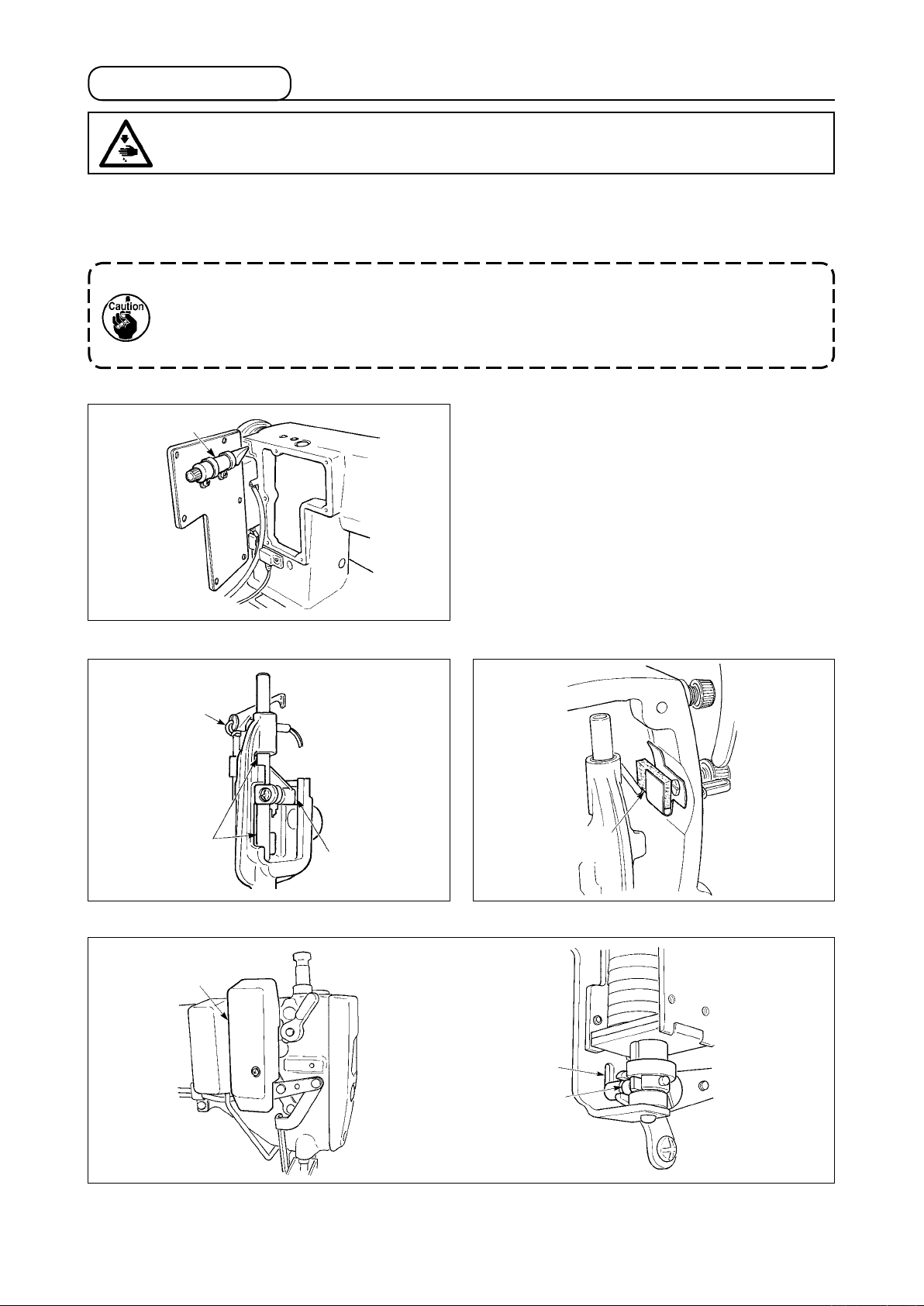
4-6. Applying grease
WARNING :
To protect against possible personal injury due to abrupt start of the machine, be sure to start the
following work after turning the power off and ascertaining that the motor is at rest.
To use the sewing machine in safety, periodically perform grease-up (standard is once in 2 to 3 years)
to the grease applying sections of the respective models with the cotton bar or the like. When using
SC-500, when the time of grease-up comes, the warning alarm sounds. When the alarm sounds,
perform grease-up.
• Never lubricate oil to the grease applying places.
• When grease is applied more than is necessary, there is a fear that grease leaks from the thread
take-up lever cover section or the needle bar. So, be careful.
• Be sure to use the grease contained in JUKI GREASE A TUBE (Part No. : 40006323) supplied with
the machine head as accessories.
[Grease keeping place]
The grease tube is installed on the inside of
A
window plate
A
.
[LH-3528, 3528-7, 3578, 3578-7]
Thread take-up
lever (oil wick)
Needle bar
Square block
[LH-3528-7, 3568-7, 3578-7, 3588-7]
1
Face plate
lubrication felt
2
3
Remove wiper cover 1, and apply grease to slot section 2 of wiper solenoid base and wiper link collar 3.
– 13 –
 Loading...