

Page 1

ENGLISH
LH-3500A Series
INSTRUCTION MANUAL
Page 2

CONTENTS
1. SPECIFICATIONS .......................................................................................................... 1
2. NAME OF EACH COMPONENT
3. INSTALLATION
3-1. Caution at the time of set-up ............................................................................................................................ 4
3-2. Installation of the sewing machine .................................................................................................................. 5
3-3. Adjusting the height of the knee lifter ............................................................................................................. 6
3-4. Installation of thread stand ............................................................................................................................... 6
.............................................................................................................. 4
...................................................................................3
4. PREPARATION OF THE SEWING MACHINE .............................................................. 7
4-1. Method of lubrication ........................................................................................................................................ 7
4-2. Lubrication to the oil tank ................................................................................................................................. 8
4-3. Draining of oil from the oil tank ....................................................................................................................... 9
4-4. Adjusting the amount of oil in the hook .......................................................................................................... 9
4-5. Oil in the feed box ........................................................................................................................................... 10
4-6. Applying grease............................................................................................................................................... 11
4-7. Setting up the SC-920 ..................................................................................................................................... 14
4-8. Installing the belt cover (For LH-3528A, 3568A, 3578A and 3588A) ........................................................... 18
4-9. Attaching the needles ..................................................................................................................................... 18
4-10. How to take out the bobbin case ................................................................................................................... 19
4-11. Inserting a bobbin in a bobbin case .............................................................................................................. 19
4-12. Threading the machine head .......................................................................................................................... 20
4-13. Thread tension ................................................................................................................................................. 23
4-14. Winding the bobbin thread ............................................................................................................................. 24
4-15. Thread take-up spring ..................................................................................................................................... 25
4-16. Adjusting the stitch length ............................................................................................................................. 27
4-17. Needle-to-hook relation .................................................................................................................................. 27
4-18. Pedal pressure and pedal stroke ................................................................................................................... 29
4-19. Adjustment of the pedal .................................................................................................................................. 29
5. OPERATION OF THE SEWING MACHINE ................................................................30
5-1. Pedal Operation ............................................................................................................................................... 30
5-2. Hand lifter ......................................................................................................................................................... 30
5-3. Adjusting the pressure of the presser foot ................................................................................................... 31
5-4. Micro-lifter ........................................................................................................................................................ 31
5-5. Thread tension release changeover when using the knee lifter ................................................................. 32
5-6. One-touch manual reverse feed (One-touch reverse feed type) ................................................................. 32
6. MAINTENANCE ...........................................................................................................33
6-1. Procedure of changing over between bottom feed and needle feed and the adjustment (for LH-3528A
only) .................................................................................................................................................................. 33
6-2. Changing the feed timing ............................................................................................................................... 35
6-3. Adjusting the thread trimming cam ............................................................................................................... 36
6-4. Adjusting the hook needle guard ................................................................................................................... 37
6-5. Adjusting the inner hook guide ...................................................................................................................... 37
6-6. Adjusting the height and the inclination of the feed dog ............................................................................ 38
6-7. Replacing the gauge ....................................................................................................................................... 39
6-8. Adjusting the thread presser spring.............................................................................................................. 39
6-9. Adjusting the position of the moving knife ................................................................................................... 40
6-10. Position of the wiper ....................................................................................................................................... 41
6-11. Caution when installing the attachments ...................................................................................................... 41
6-12. Replacing the bobbin thread slack preventer spring (For LH-3568A, 3568A-7, 3588A and 3588A-7) ..... 42
6-13. Stop of the needle bars and angle of corners for corners stitching (For LH-3568A, 3568A-7, 3588A and
3588A-7)............................................................................................................................................................ 42
7. STITCH-TO-ANGLE TABLE BY GAUGE (PITCH AND mm CONVERSION TABLE) 43
8. GAUGE SETS
..............................................................................................................44
9. TROUBLES AND CORRECTIVE MEASURES
10. MOTOR PULLEY AND BELT
...................................................................................... 55
i
........................................................... 53
Page 3

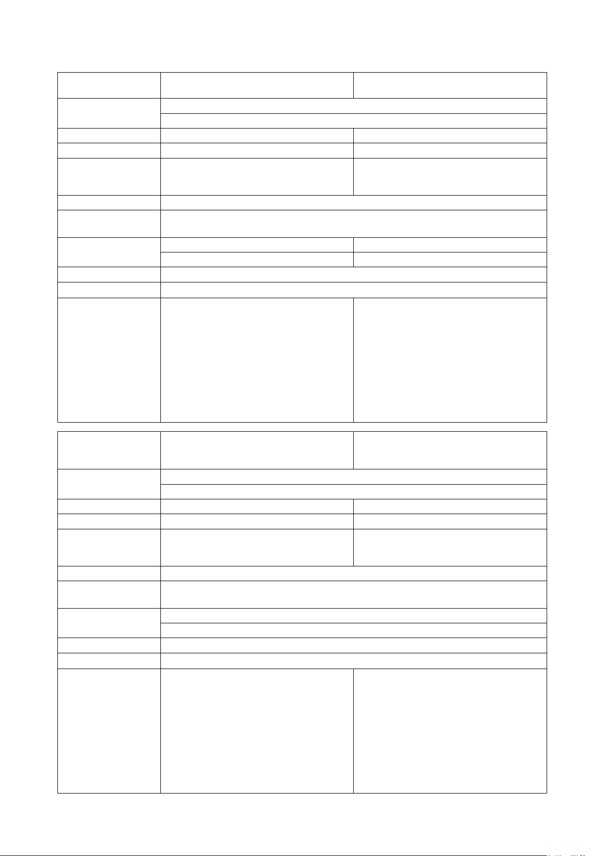
1. SPECIFICATIONS
Model name LH-3528A
Application
S type : standard, F type : foundation, A type : light-weight materials, G type : jeans
For light -, medium - and heavy - weight materials
(with automatic thread trimmer)
LH-3528A-7
Hook Standard hook Standard hook
Thread trimmer Not provided Provided
Separately
driven needle bar
Not provided Not provided
mechanism
Max. sewing speed
Needle
* 1
Gauge size
GROZ-BECKERT 134 Nm9 to Nm16 (For S, F and A types), 134 Nm16 to Nm23 (G type) (For S, F and A types), 134 Nm16 to Nm23 (G type)134 Nm16 to Nm23 (G type) (G type)
ORGAN needle DP x 5 #9 to #16 (For S, F and A types), DP x 5 #16 to #23 (G type)DP x 5 #9 to #16 (For S, F and A types), DP x 5 #16 to #23 (G type)
3/32" to 1-1/2" 1/8" to 1-1/4"
2.4 to 38.1 mm 3.2 to 31.8 mm
3,000 sti/min
Lift of presser foot 13 mm by knee lifter, 7 mm by hand lifter lever
Lubrication JUKI NEW DEFRIX OIL No. 1 or JUKI MACHINE OIL #7
Noise
Declaration
- Equ iva lent c ontinuou s emission so und
pressure level (L
) at the workstation :
pA
A-weighted value of 87.5 dB ; (Includes
K
= 2.5 dB) ; according to ISO 10821-
pA
C.6.2 -ISO 11204 GR2 at 3,000 sti/min.
- Sound power level (LWA) :
A-weighted value of 91.5 dB ; (Includes
KpA = 2.5 dB) ; according to ISO 10821C.6.2 -ISO 3744 GR2 at 3,000 sti/min.
Declaration
- Equ iva lent c ontinuou s emission so und
pressure level (L
) at the workstation :
pA
A-weighted value of 85.5 dB ; (Includes
K
= 2.5 dB) ; according to ISO 10821-
pA
C.6.2 -ISO 11204 GR2 at 3,000 sti/min.
- Sound power level (LWA) :
A-weighted value of 90.5 dB ; (Includes
K
= 2.5 dB) ; according to ISO 10821-
pA
C.6.2 -ISO 3744 GR2 at 3,000 sti/min.
LH-3568A-7
corner stitching)
Model name
Application
LH-3568A
(with incorporating corner stitching)
For light -, medium - and heavy - weight materials
S type : standard, G type : jeans
(with automatic thread trimmer incorporating
Hook Standard hook Standard hook
Thread trimmer Not provided Provided
Separately
driven needle bar
Provided Provided
mechanism
Max. sewing speed
Needle
* 1
Gauge size
GROZ-BECKERT 134 Nm9 to Nm16 (S type), 134 Nm16 to Nm23 (G type) (S type), 134 Nm16 to Nm23 (G type)134 Nm16 to Nm23 (G type) (G type)
ORGAN needle DP x 5 #9 to #16 (S type), DP x 5 #16 to #23 (G type)DP x 5 #9 to #16 (S type), DP x 5 #16 to #23 (G type)
3,000 sti/min
1/8" to 3/4"
3.2 to 19.1 mm
Lift of presser foot 13 mm by knee lifter, 7 mm by hand lifter lever
Lubrication JUKI NEW DEFRIX OIL No. 1 or JUKI MACHINE OIL #7
Declaration
- Equ iva lent c ontinuou s emission so und
pressure level (L
A-weighted value of 83.5 dB ; (Includes
K
= 2.5 dBA) ; according to ISO 10821-
Noise
PA
C.6.2 -ISO 11204 GR2 at 3,000 sti/min.
- Sound power level (LWA) :
A-weighted value of 87.5 dB ; (Includes
K
= 2.5 dBA) ; according to ISO 10821-
pA
C.6.2 -ISO 3744 GR2 at 3,000 sti/min.
* 1
: Needle used depends on the destination.
) at the workstation :
pA
Declaration
- Equ iva lent c ontinuou s emission so und
pressure level (L
) at the workstation :
pA
A-weighted value of 84 dBA ; (Includes
K
= 2.5 dB) ; according to ISO 10821-
PA
C.6.2 -ISO 11204 GR2 at 3,000 sti/min.
- Sound power level (LWA) :
A-weighted value of 88.5 dBA ; (Includes
K
= 2.5 dB) ; according to ISO 10821-
pA
C.6.2 -ISO 3744 GR2 at 3,000 sti/min.
– 1 –
Page 4
Model name LH-3578A
Application
For medium - and heavy - weight materials
(with automatic thread trimmer)
G type : jeans
LH-3578A-7
Hook Large hook Large hook
Thread trimmer Not provided Provided
Separately
driven needle bar
Not provided Not provided
mechanism
Max. sewing speed
Needle
* 1
Gauge size
Lift of presser foot
GROZ-BECKERT 134 Nm16 to Nm23 (G type) (G type)
ORGAN needle DP x 5 #16 to #23 (G type)DP x 5 #16 to #23 (G type)
3/16" to 1-1/12" 3/16" to 3/8"
4.8 to 38.1 mm 4.8 to 9.5 mm
13 mm by knee lifter, 7 mm by hand lifter lever
3,000 sti/min
Lubrication JUKI NEW DEFRIX OIL No. 1 or JUKI MACHINE OIL #7
Noise
Declaration
- Equ iva lent c ontinuou s emission so und
pressure level (L
) at the workstation :
pA
A-weighted value of 87.5 dB ; (Includes
K
= 2.5 dB) ; according to ISO 10821-
pA
C.6.2 -ISO 11204 GR2 at 3,000 sti/min.
- Sound power level (LWA) :
A-weighted value of 91.5 dB ; (Includes
KpA = 2.5 dB) ; according to ISO 10821C.6.2 -ISO 3744 GR2 at 3,000 sti/min.
Declaration
- Equ iva lent c ontinuou s emission so und
pressure level (L
) at the workstation :
pA
A-weighted value of 85.5 dB ; (Includes
K
= 2.5 dB) ; according to ISO 10821-
pA
C.6.2 -ISO 11204 GR2 at 3,000 sti/min.
- Sound power level (LWA) :
A-weighted value of 90.5 dB ; (Includes
K
= 2.5 dB) ; according to ISO 10821-
pA
C.6.2 -ISO 3744 GR2 at 3,000 sti/min.
LH-3588A-7
corner stitching)
Model name
Application
LH-3588A
(with incorporating corner stitching)
For medium - and heavy - weight materials
(with automatic thread trimmer incorporating
G type : jeans
Hook Large hook Large hook
Thread trimmer Not provided Provided
Separately
driven needle bar
Provided Provided
mechanism
Max. sewing speed
Needle
* 1
Gauge size
Lift of presser foot
GROZ-BECKERT 134 Nm16 to Nm23 (G type) (G type)
ORGAN needle DP x 5 #16 to #23 (G type)DP x 5 #16 to #23 (G type)
13 mm by knee lifter, 7 mm by hand lifter lever
3,000 sti/min
3/16" to 3/8"
4.8 to 9.5 mm
Lubrication JUKI NEW DEFRIX OIL No. 1 or JUKI MACHINE OIL #7
Declaration
- Equ iva lent c ontinuou s emission so und
pressure level (L
A-weighted value of 83.5 dB ; (Includes
K
= 2.5 dBA) ; according to ISO 10821-
Noise
PA
C.6.2 -ISO 11204 GR2 at 3,000 sti/min.
- Sound power level (LWA) :
A-weighted value of 87.5 dB ; (Includes
K
= 2.5 dBA) ; according to ISO 10821-
pA
C.6.2 -ISO 3744 GR2 at 3,000 sti/min.
* 1
: Needle used depends on the destination.
) at the workstation :
pA
Declaration
- Equ iva lent c ontinuou s emission so und
pressure level (L
) at the workstation :
pA
A-weighted value of 84 dBA ; (Includes
K
= 2.5 dB) ; according to ISO 10821-
PA
C.6.2 -ISO 11204 GR2 at 3,000 sti/min.
- Sound power level (LWA) :
A-weighted value of 88.5 dBA ; (Includes
K
= 2.5 dB) ; according to ISO 10821-
pA
C.6.2 -ISO 3744 GR2 at 3,000 sti/min.
– 2 –
Page 5
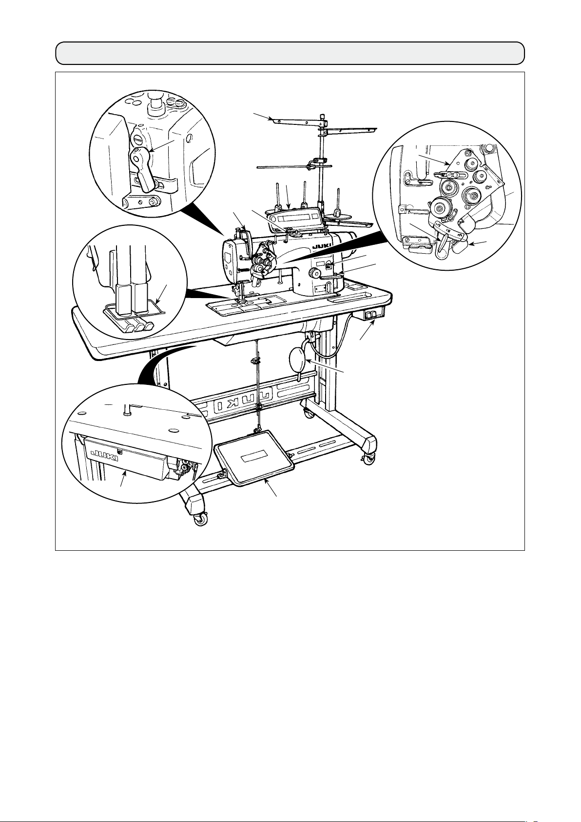
2. NAME OF EACH COMPONENT
!2
!5
!1
2
3
4
!0
1
9
!3
!4
5
Separately driven needle changeover lever
1
(LH-3568A, 3568A-7, 3588A, 3588A-7)
Thread take-up cover
2
Finger guard
3
Thread tension controller
4
Control box
5
Pedal
6
Knee pad
7
8
7
6
Power switch
8
Reverse feed switch
9
(LH-3528A-7, 3568A-7, 3528A (F type), 3578A-7
3588A-7)
Operation panel
!0
Bobbin winder
!1
Thread stand
!2
Oil supply opening
!3
Reverse feed control lever
!4
Hand lifter lever
!5
,
– 3 –
Page 6
3. INSTALLATION
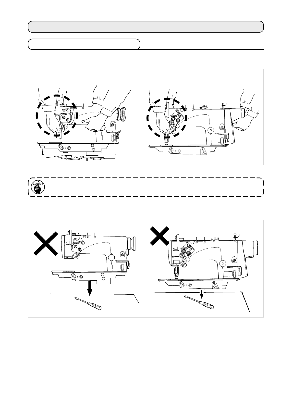
3-1. Caution at the time of set-up
(1) Transporting procedure of the sewing machine
[LH-3528A, 3568A, 3578A, 3588A] [LH-3528A-7, 3568A-7, 3578A-7, 3588A-7]
Hold and transport the sewing machine with two persons as shown in the illustration.
When carrying the sewing machine, take extreme care not to hold the thread tension controllers
by hand. (If you hold the thread tension controllers by hand, they can break.)
(2) Caution when placing the sewing machine
Do not put protruding articles such as the screwdriver and the like at the location where the sewing machine
is placed.
– 4 –
Page 7
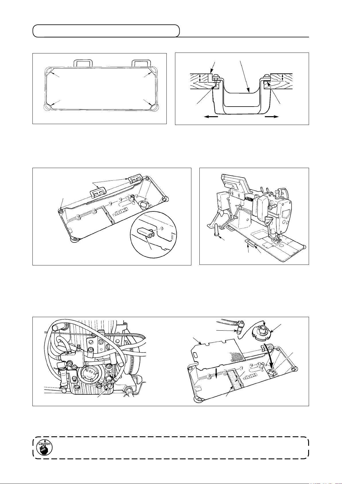
3-2. Installation of the sewing machine
(1) Installing the under cover
3
1
1) The under cover should rest on the four corners
of the machine table groove.
7
8
3
1
A
4
18.5mm
3
B
1
22.5mm
2
2) Fix two rubber seats 1 on side A (operator’s
side) using nails 2 as illustrated above. Fix two
cushion seats 3 on side B (hinged side) using a
rubber-based adhesive. Then place under cover
on the xed seats.
4
6
3) Mount rubber hinge seats 7 on the table and x the
table with nails.
Insert hinge 6 into the machine main body. Engage the hing-
es with rubber hinge seats 7 mounted on the table. Then,
put the machine head down on the machine head cushions
which are located at the four corners of the table.
8
!0
9
6
7
4) Attach head support rod 9 to the table.
!1
!0
!3
D
!2
C
5) Detach inlet port !0 for circulation which is xed on the feed box cover. Insert the inlet port into lter !1
until it will go no further without fail and place them in opening C.
Place urethan lter !2 on D, and place lter !3 of thin plate type (small mesh plate) on it.
Circulation trouble may occur unless inlet port !0 for circulation is securely inserted into ler !1
until it goes no further.
– 5 –
Page 8
3-3. Adjusting the height of the knee lifter
WARNING :
To protect against possible personal injury due to abrupt start of the machine, be sure to start the
following work after turning the power off and ascertaining that the motor is at rest.
2
1
1) The standard height of the presser foot lifted using the knee lifter is 12 mm.
2) You can adjust the presser foot lift up to 13 mm using knee lifter adjust screw 1.
Do not operate the sewing machine in the state that the presser foot 3 is lifted by 12 mm or
more since the needle bar 2 comes in contact with the presser foot 3.
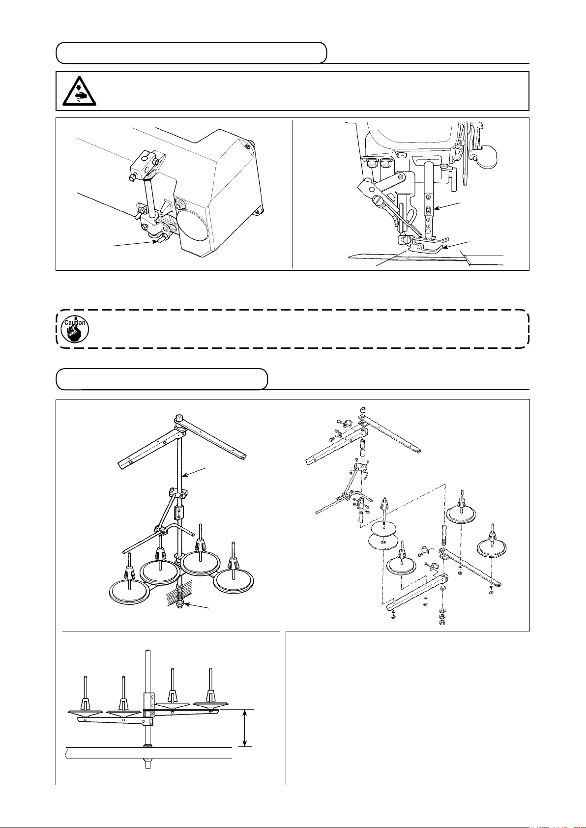
3-4. Installation of thread stand
2
3
1
Assemble the thread stand, set it up on the machine
table using the installation hole in the table and
tighten nut 1 gently.
300 mm from the top
surface of table
When you use power supplied by the overhead
power line, pass the power supply cord through hol-
low spool rest rod 2.
– 6 –
Page 9
4. PREPARATION OF THE SEWING MACHINE
4-1. Method of lubrication
For this sewing machine, one of two different lubricating methods can be selected.
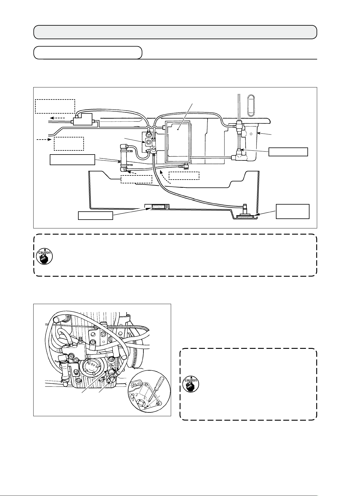
(1) Method of circulating lubrication (when the oil collected in the under cover is reused)
Lubrication to
hook side
Reux oil
from hook
Filter for plunger
To ensure the long service life of the sewing machine, be sure to clean up the aforementioned
lter sections (at four locations) periodically (approximately once three months). When the lter
is clogged, lubrication trouble will occur and break-down will be caused.
In addition, when the oil becomes dirty, replace the oil gathered in the oil tank and the under
cover.
Plunger
Urethan lter
Lubrication
Oil tank
Ball oat case
Oil inlet lter
Circulation
Filter for
circulation
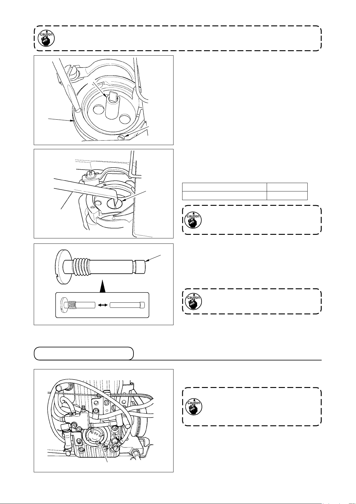
(2) Method of non-circulation type lubrication (when only the clean oil is always used)
Insert inlet port 1 for circulation into section 3 of
the feed box cover until it will go no further to put it
into the state as it has been delivered to your plant.
* Drain oil dropped into the under cover by remov-
ing drain screw 2.
When inlet port for circulation 1 comes
in contact with the oil surface, oil is
absorbed without passing the lter. As a
result, break-down will be caused.
If inlet port 1 for circulation is not insert-
3
1
2
ed into the feed box cover, oil may leak
from inlet port 1 for circulation or the
quantity of oil in the hook may uctuate.
– 7 –
Page 10
4-2. Lubrication to the oil tank
WARNING :
1. Do not connect the power plug until the lubrication has been completed so as to prevent
accidents due to abrupt start of the sewing machine,
2. To prevent the occurrence of an inammation or rash, immediately wash the related portions if
oil adheres to your eyes or other parts of your body.
3. If oil is mistakenly swallowed, diarrhea or vomitting may occur. Put oil in a place where children
cannot reach.
Lower
engraved
marker line
3
2
1
Upper
engraved
marker line
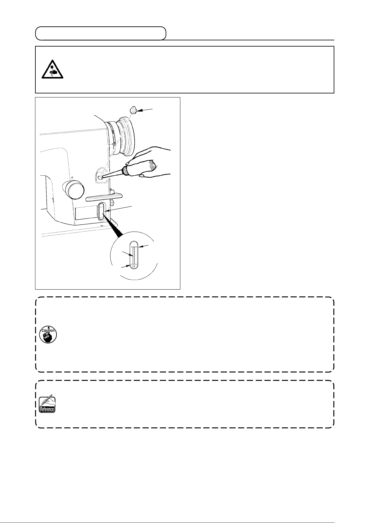
Fill the oil tank with oil for hook lubrication before
operating the sewing machine.
1) Remove oil hole cap 1 and ll the oil tank with
JUKI NEW DEFRIX OIL No.1 (Part No. : MD-
FRX1600C0) or JUKI MACHINE OIL #7 (Part
No. : MML007600CA) using the oiler supplied
with the machine.
2) Add oil until the top end of oil amount indicating
rod 3 does not go above the upper engraved
marker line.
If the oil tank is lled with an excessive amount
of oil, oil will leak from the air vent hole in the ball
oat case or proper lubrication will not be carried
out. So, be careful.
3) When you operate the sewing machine, rell oil if
the top end of oil amount indicating rod 3 comes
down to the lower engraved marker line of oil
amount indicating window 2.
• For the rst time you ll the oil tank with oil, add 280 cc of oil as a guide and check to be sure
that the oil amount indicating rod works. If the oil amount indicating rod does not work, bring it
to the workable state by tiling the sewing machine once.
• When you use a new sewing machine or a sewing machine after an extended period of disuse,
use the sewing machine after performing break-in at 2,000 sti/min or less.
• For the oil for hook lubrication, purchase JUKI NEW DEFRIX OIL No. 1 (Part No. : MD-
FRX1600C0) or JUKI MACHINE OIL #7 (Part No. : MML007600CA).
• Be sure to lubricate clean oil.
In case of the circulation type lubrication method, when using the sewing machine for the rst
time, the oil amount in the oil tank decreases until the oil has collected in the ler for circulation.
When the top end of oil amount indicating rod is lower than the lower engraved marker line, add
the oil to the oil tank again so that the top end enters between the upper and lower engraved
marker lines.
– 8 –
Page 11
4-3. Draining of oil from the oil tank
WARNING :
1. To prevent accidents caused by abrupt start of the sewing machine, do not connect the power
plug until draining of oil has been completed.
2. To prevent the occurrence of an inammation or rash, immediately wash the related portions if
oil adheres to your eyes or other parts of your body.
3. If oil is mistakenly swallowed, diarrhea or vomitting may occur. Put oil in a place where children
cannot reach.
1
When draining oil from the oil tank, loosen and re-
move oil conrming window 1.
Oil may burst out from the oil conrming
window at the time of draining.
It is recommended, in this case, only to
loosen the oil conrming window instead
of removing it. Then, drain oil while con-
trolling the oil amount bursting out from
the oil amount conrming window 1.
4-4. Adjusting the amount of oil in the hook
WARNING :
To protect against possible personal injury due to abrupt start of the machine, be sure to start the
following work after turning the power off and ascertaining that the motor is at rest.
1
Oil amount
decreases
Adjust the amount oil using adjusting screw 1. Turn screw 1 clockwise to increase the amount of oil in the
hook or counterclockwise to decrease it. Measure the amount of oil in ve seconds. When the amount of oil
is excessively decreased, break-down will be caused. So, be careful.
Oil splashes
Oil a mount
increases
– 9 –
Page 12
To use in safety, replace the oil wick of hook section with a new one approximately once a year
with the procedure below.
1
3
4
2
1) Loosen setscrews
large hook : 3 places) and remove hook gib
2) Remove inner hook
(small hook : 2 places,
2
.
3
1
.
3) Loosen oil plug 4 with the L-shaped screwdriver
(Part No. : B9101490000) and remove it.
4) �raw out oil wick 5 inserted into oil plug 4, and
replace it with a new one.
[Part No. of oil wick 5]
Small hook / Large hook/ Large hookLarge hook 11015906
Oil Q’ty in the hook is largish 11404704
When strongly pressing oil wick 5, it may
be broken. Lightly insert it to such an
extent that it is not drawn out.
4-5. Oil in the feed box
5
After the replacement, assemble oil plug
inner hook 3 and hook gib
to the hook by
1
4
,
reversing the above procedure.
Perform conrming of oil splash.
When loosening/assembling, do not allow
the slit section of oil plug 4 to be burred.
When using the sewing machine, make sure that the
oil is put in the feed box from oil conrming window 1.
If you nd abnormal discoloring of oil
or dust in the oil through the oil amount
indicating window, loosen the window to
drain oil and ll the oil tank with new oil.
1
– 10 –
Page 13
4-6. Applying grease
WARNING :
To protect against possible personal injury due to abrupt start of the machine, be sure to start the
following work after turning the power off and ascertaining that the motor is at rest.
To use the sewing machine in safety, periodically perform grease-up (standard is once in 2 to 3 years) to the
grease applying sections of the respective models with the cotton bar or the like. When using SC-920, when
the time of grease-up comes, the warning alarm sounds. When the alarm sounds, perform grease-up.
• Never lubricate oil to the grease applying places.
• When grease is applied more than is necessary, there is a fear that grease leaks from the thread
take-up lever cover section or the needle bar. So, be careful.
• Be sure to use the grease contained in JUKI GREASE A TUBE (Part No. : 40006323) supplied
with the machine head as accessories.
(1) Sections to be applied with grease
[LH-3528A, 3528A-7, 3578A, 3578A-7]
Thread take-up
lever (oil wick)
Needle bar
Square block
Face plate
lubrication felt
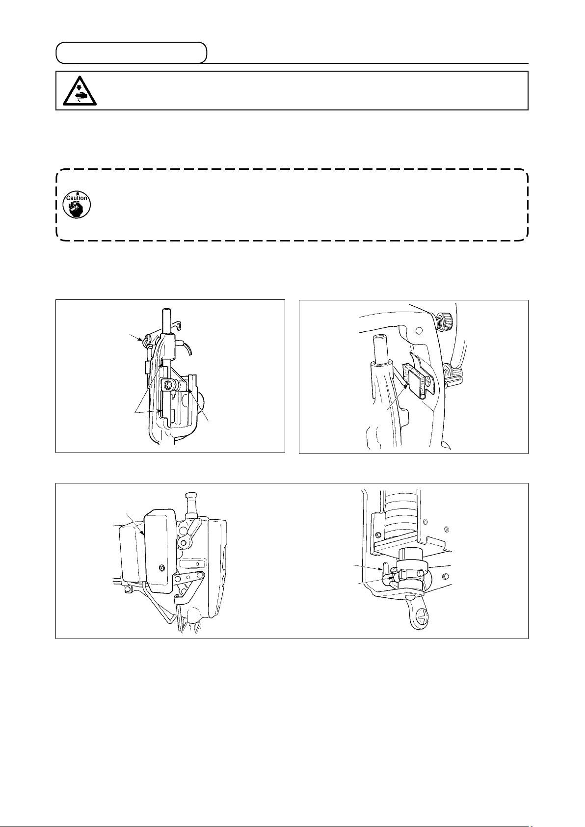
[LH-3528A-7, 3568A-7, 3578A-7, 3588A-7]
1
2
3
Remove wiper cover 1, and apply grease to slot section 2 of wiper solenoid base and wiper link collar 3.
– 11 –
Page 14
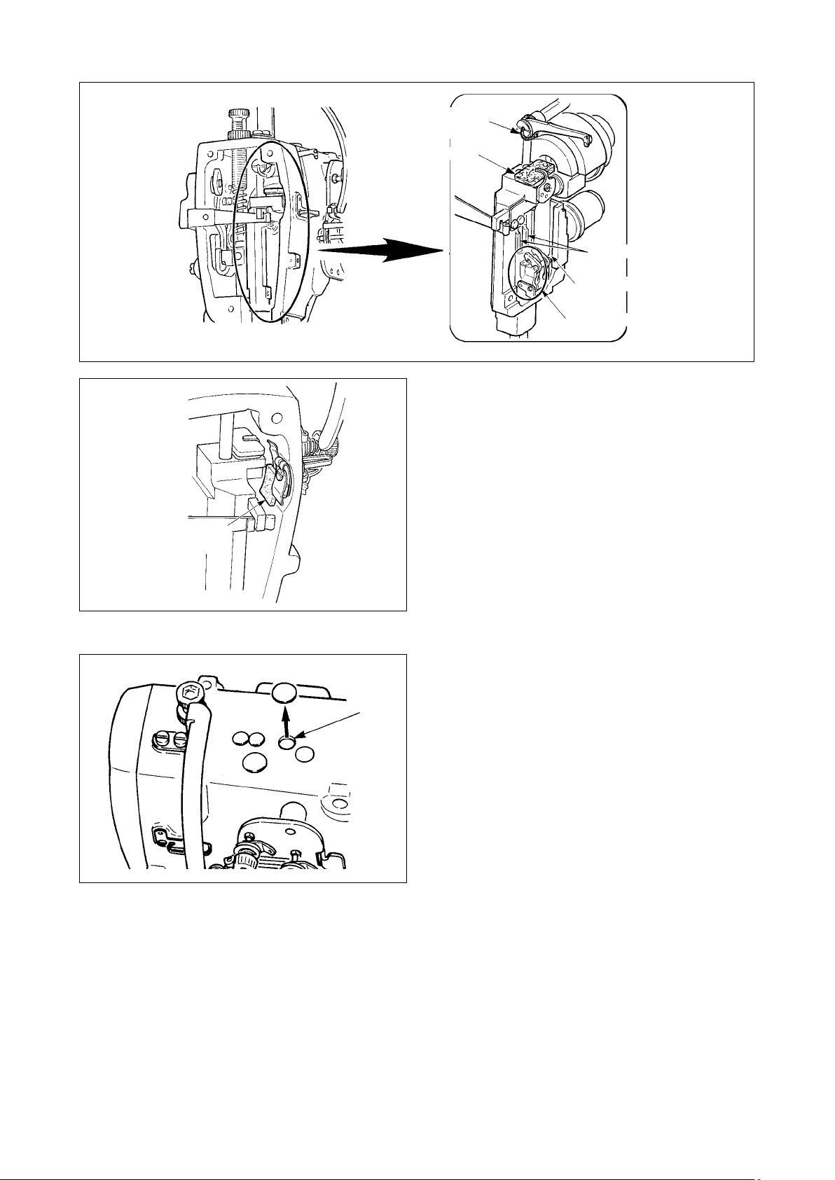
[LH-3568A, 3568A-7, 3588A, 3588A-7]
Thread take-up
lever (oil wick)
Felt
Needle bar
Square block
Needle bar bracket
[Common]
Face plate
lubrication felt
A
Remove the rubber cap, take out the felt in A, pour
new grease in the hole, and put the felt to which
grease has been soaked after removing old grease
adhered to the inside of the hole and the felt.
Further, pour grease above the felt and cover it with
the rubber cap.
– 12 –
Page 15
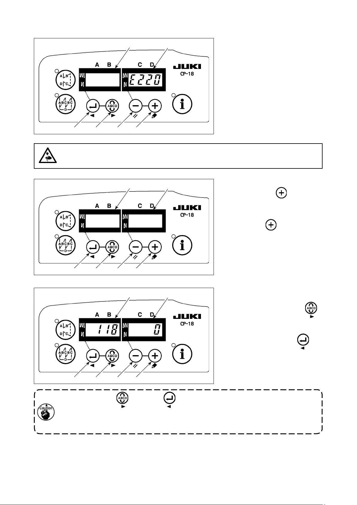
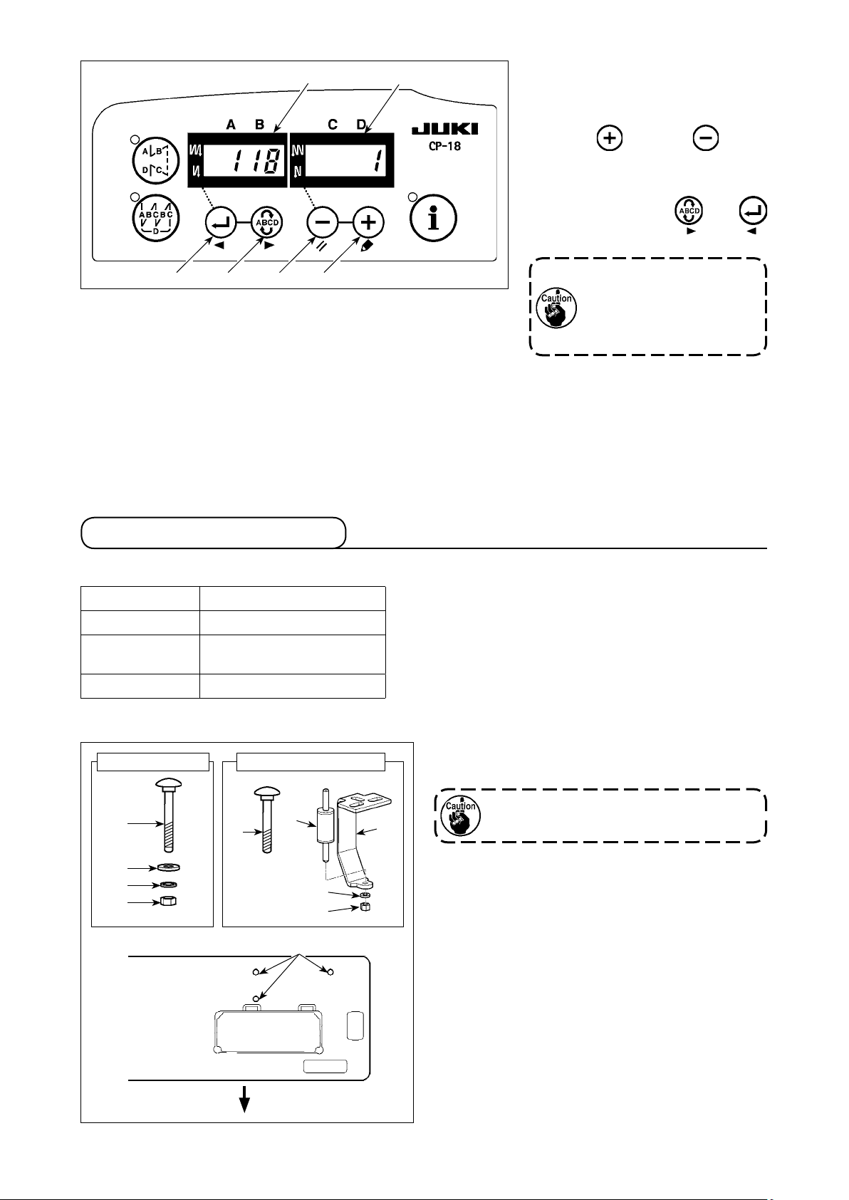
(2) Releasing procedure of the grease-up warning for SC-920
When the time of grease-up has
come, screen display of LED 5 on
the left-hand gure becomes "E220".
After performing grease-up, release
the warning following the procedure
below.
1
6
2 3 4
5
WARNING :
To avoid possible personal injuries caused by movement other than that you desired, do not operate
the switches in the procedure other than those required, as described below, to specify the functions.
6
5
1) Turn OFF the power to the unit.
2) Pressing switch
the power to the unit.
3) When the screen is displayed,
, turn ON
4
1
1
2 3 4
6
2 3 4
5
keep switch
for three seconds until the buzzer
sounds twice.
4) Set the setting No.6 to "118".
When you want to advance the
setting No.6, press switch
to advance the setting No.
2
When you want to return the set-
ting No.6, press switch
to return the setting No.
held pressed
4
6
6
1
Keep pressing switch 2 or switch 1, and the setting No. 6 will advance (return)
continuously. If the setting No. 6 is moved forward (or backward), the previous (or subsequent)
content of the setting is conrmed. Be careful when the content of a setting is changed (when
the up / down switch is touched).
– 13 –
Page 16
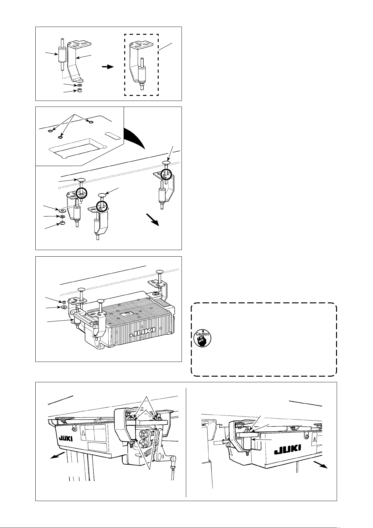
6
5
5) When setting No. 6 is adjusted
to "118", the current set value is
displayed on LED 5. Then Press
switch 4 (switch 3) to
change to "1".
6) When the change has been com-
pleted, press switch 2 or
to specify the changed value.
1
1
2 3 4
After completion of the operation, turn the power OFF and re-turn it
ON to restore the normal operation.
When turning OFF the
power before performing
this work, the contents
which have been changed
are not updated.
(3) Releasing procedure of the grease-up “error” For SC-920
When using the machine for a certain period of time after the display of error No. 220 (continuing using the
machine without performing grease-up at the time of displaying No. 220), error No. 221 is displayed and the
machine stops running.
In this case, apply grease to the specied sections, then reset the error according to the description given in
"(2) Releasing procedure of the grease-up warning for SC-920" p. 13
.
After completion of the operation, turn the power OFF and re-turn it ON to restore the normal operation.
4-7. Setting up the SC-920
(1) Specications
Supply voltage 3-phase 200 to 240V
Frequency 50Hz/60Hz
Operating envi-
ronment
Input 320VA
Temperature : 0 to 40˚C
Humidity : 90% or less
(2) Installing on the table (LH-3528A-7, 3568A-7, 3578A-7 and 3588A-7)
Parts supplied with SC-920
×
8
9
!0
Table
Parts supplied with LH-3500A
6
1
7
4
1
Operator side
3
1) Hammer decoration boltHammer decoration bolt 1 supplied with the LH-
3500A into table.
The decoration bolt supplied with the
SC-920 is not used.
– 14 –
Page 17
6
7
4
3
2
2)
Fix rubber cushion 6 on control-box mounting plate
with nut 4 and spring washer 7. Three sets of
3
are required.
2
Table
8
9
!0
4
1B
1
1A
1B
Operator side
3) Fix control-box mounting plates 2 assembled
in step 2) on the table with decoration bolts 1,
washers 8, spring washers 9 and nuts !0.
Screw
at one location this side as observed
1A
from the operator should be securely tightened,
and two screws
at two locations far side
1B
from the operator should be temporarily tight-
ened.
* Install control-box mounting plate 3 as illustrat-
ed in the gure, carefully checking the installing
direction and the location of holes.
* The washers, spring washers and nuts supplied
with the SC-920 should be used.
4) Place the SC-920 on rubber cushions 6 and x
with nuts 4 and washers 5.
Install the control box while carefully changing the
position of the temporarily-xed control-box mounting
plate (right one as observed from the worker).
5
6
Away from the
operator side
4
5
6
1. If you use the decoration bolt supplied
with the SC-920, the control box cannot
be installed since the bolt interferes with
the control box.
2. If the control-box mounting plates are
xed on the table in a wrong installing
direction or with the hole located at a
wrong position, the control box cannot
be installed.
4
5
6
Away from the
operator side
– 15 –
Page 18
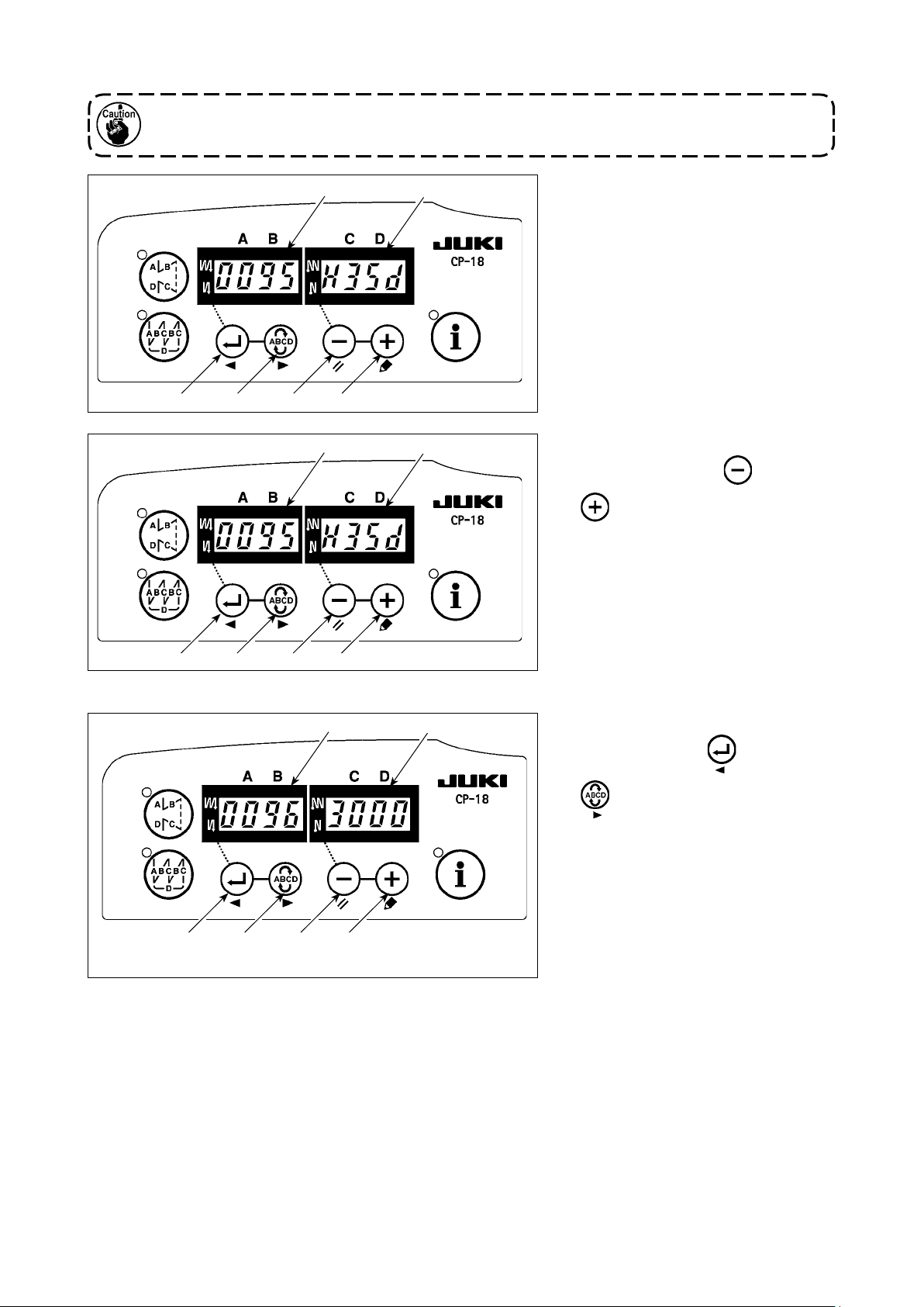
(3) Setting procedure of the machine head
For the operation panel other than CP-18, refer to the Instruction Manual for the operation panel
to be used for the setting procedure of the machine head.
1
1
6
2 3 4
6
2 3 4
5
5
1) Call function setting No. 95 refer-
ring to
SC-920"
"#-6. Setting functions of
in the Instruction Manual
for the SC-920.
2) The type of machine head can be
selected by pressing switch 3 (
switch 4).
* Refer to "CAUTIONS WHEN SET-
TING UP THE SEWING MACHINE"
or "Machine head list" on the sepa-
rate sheet for the types of machine
heads.
1
6
2 3 4
5
3) After selecting the type of machine
head, by pressing switch 1 (
switch 2), the step proceeds to
96 or 94, and the display automati-
cally changes to the contents of the
setting corresponding with the type
of machine head.
– 16 –
Page 19

(4) Adjusting the machine head (LH-3528A-7, 3568A-7, 3578A-7 and 3588A-7)
When the slip between the white marker dot on the handwheel and the concave of the cover is
excessive after thread trimming, adjust the angle of the machine head by the operation below.
1
6
2 3 4
6
5
5
1) Simultaneously pressing
switch 2 and switch 3, turn
ON the power switch.
2) is displayed (6) in the in-
dicator and the mode is changed
over to the adjustment mode.
3) Turn the pulley of the machine
head by hand until the main-shaft
reference signal is detected. At
this time, the degree of an angle
from the main-shaft reference
signal is displayed on the indica-
tor 5. (The value is the reference
value.)
1 2 3 4
8
6
5
4) In this state, align the white dot 7 of the hand-
7
wheel with the concave 8 of the pulley cover as
shown in the gure.
5) Press switch 4 to nish the
adjustment work. (The value is the
reference value.)
1
2 3 4
– 17 –
Page 20

4-8. Installing the belt cover (For LH-3528A, 3568A, 3578A and 3588A)
WARNING :
To protect against possible personal injury due to abrupt start of the machine, be sure to start the
following work after turning the power off and ascertaining that the motor is at rest.
LH-3528A, 3568A
LH-3578A, 3588A
1
2
1) Drill guide holes A and B of wood screws in the table.
2) Temporarily x belt cover B 1 to the place of guide holes A and B.
3) Install belt cover A 2 to the arm installing section.
4) Adjust the position of belt cover B 1 and x it with wood screw.
4-9. Attaching the needles
67
A
47
B
(mm)
WARNING :
To protect against possible personal injury due to abrupt start of the machine, be sure to start the
following work after turning the power off and ascertaining that the motor is at rest.
[LH-3568A, 3568A-7, 3588A and 3588A-7]
2
1
[LH-3528A(S type and G type), 3528A-7, 3578A and
3578A-7]
2
1
2
1
3
2
1
3
[LH-3528A(A type and F type)]
2
1
2
1
3
Switch "off" the motor.
Use DPx5(134) needles.
1) Turn the handwheel until the needle bar has
come up to the highest point of its stroke.
2) Loosen needle clamp screws 2 and pick up two
needles 1 in the way that their grooves 3 are
facing outwards.
3) Insert the needles into the needle clamp as far
as they will go.
4) Tighten needle clamp screws 2 rmly.
– 18 –
Page 21

4-10. How to take out the bobbin case
WARNING :
To protect against possible personal injury due to abrupt start of the machine, be sure to start the
following work after turning the power off and ascertaining that the motor is at rest.
1
4-11. Inserting a bobbin in a bobbin case
1) Lift latch 1 and take out the bobbin case and the
bobbin together.
2) Hold the bobbin case by latch raised, put it into
the shaft in the hook correctly and release the
latch.
WARNING :
To protect against possible personal injury due to abrupt start of the machine, be sure to start the
following work after turning the power off and ascertaining that the motor is at rest.
[LH-3568A, 3568A-7, 3588A and 3588A-7]
A
3
4
2
1
[LH-3528A, 3528A-7, 3578A and 3578A-7]
A
1
1) Set a bobbin to the bobbin case so that the bob-
bin turns in the direction of arrow mark A.
2) Pass the thread through thread slit 1 in the bob-
bin case and draw the thread and pull the thread
so that it passes under the tension spring.
3) Pass thread through another thread slit 2 then,
pass it through thread slit 3 on the bobbin case
from the inside.
4) Put the thread on bobbin threads slack preventer
spring 4.
1) Set a bobbin to the bobbin case so that the bob-
bin turns in the direction of arrow mark A.
2) Pass the thread through thread slit 1 in the hook
and draw the thread and pull it so that it passes
under the tension spring.
– 19 –
Page 22

4-12. Threading the machine head
[S type and G type] LH-3528A, 3528A-7, 3568A and 3568A-7
WARNING :
To protect against possible personal injury due to abrupt start of the machine, be sure to start the
following work after turning the power off and ascertaining that the motor is at rest.
A
1
!0
Fig. 6 Fig. 7
Left-hand
needle thread
-
!0
-
!1
-
!2
-
!3
K
L
M
N
Right-hand
needle thread
!4
!5
K
2
O
P
B
Intermediate
thread guide
4
3
D
8
-
H
6
5
E
F
-
7
G
* Needle thread take-up eyelet is not
usually used.
8 mm
For lament
thread, thread the
machine head as
illustrated.
(The needle
thread take-up
eyelet should be
used for lament
thread.)
C
S type G type
Fig. 1
Fig. 2
Fig. 3
Fig. 4
Thread the machine head following the order as illustrated in the gure.
Pass the left-hand needle thread, toward the machine head, in the order of 1 to !5. Pass the right-hand
needle thread in the order of A to P.
1. Carefully check how to thread the needle clamp thread guides (!4, O).
・ (S type) See Fig 1 for polyester spun thread, Fig. 2 for thick lament thread of yarn count #50
or lower and around #50, or Fig 3 for thin lament thread of yarn count #50 or higher.
・ (G type) See Fig. 4 for thick thread of yarn count #5 to #30.
2. When using lament thread for sewing, use the felt thread guides supplied with the sewing ma-
chine. If the needle thread loosens or breaks, take some preventive measure such as winding
the thread on the needle (S type).
3. To produce chain-off thread, the felt thread guide (in Fig. 2 or Fig. 3) should be used for the S
type, or the needle thread presser (in Fig. 5) should be used for the G type.
4. For the LH-3528A-7 or LH-3568A-7, thread the intermediate thread guide as follows:
・ For polyester spun thread, see Fig. 6. For lament thread, see Fig. 7.
– 20 –
Fig. 5
Page 23

[G type] LH-3578A, 3578A-7, 3588A and 3588A-7
WARNING :
To protect against possible personal injury due to abrupt start of the machine, be sure to start the
following work after turning the power off and ascertaining that the motor is at rest.
A
1
!0
Fig. 1 Fig. 2
Left-hand
needle thread
-
!0
-
!1
-
!2
-
!3
K
L
M
N
Right-hand
needle thread
!4
!5
K
2
O
P
B
8
-
H
Intermediate
thread guide
14 mm
5
6
-
7
G
F
4
3
C
D
E
Thread the machine head following the order as illustrated in the gure.
Pass the left-hand needle thread, toward the machine head, in the order of 1 to !5. Pass the right-hand
needle thread in the order of A to P.
1. Thread guide (
tion. If the thread guide is inclined excessively, the needle thread can tangle on thread guide (!3,
). So, carefully adjust the inclination of the thread guide.
N
2. For the LH-3578A-7 or LH-3588A-7, thread the intermediate thread guide as follows:
For polyester spun thread, see Fig. 1. For lament thread, see Fig. 2.
・
, M) is able to prevent the needle thread from apping according to its inclina-
!2
– 21 –
Page 24

[A type and F type]
WARNING :
To protect against possible personal injury due to abrupt start of the machine, be sure to start the
following work after turning the power off and ascertaining that the motor is at rest.
Left-hand
needle thread
-
!0
K
-
!1
L
-
!2
M
!0
Intermediate
K
thread guide
Right-hand
needle thread
Fig. 3
2
Fig. 4
A
1
B
-
!3
N
D
34
C
!4
!5
O
P
J
9
Fig. 1
Fig. 2
8
-
6
I
5
F
E
7 H G
Thread the machine head following the order as illustrated in the gure.
Pass the left-hand needle thread, toward the machine head, in the order of 1 to !5. Pass the right-hand
needle thread in the order of A to P.
1. Be careful of threading of needle clamp thread guides (!4, O).
・ See Fig. 1 for thin lament thread of yarn count #50 or higher, and Fig. 2 for thick lament
thread of yarn count #50 or lower, lament thread around yarn count #50 and polyester spun
thread.
2. Pass right-side needle thread through the upper side of thread guide pin H.
3. Pass the thread through the intermediate thread guide of LH-3528A-7 and 3568A-7 as follows.
・ Fig. 3 for polyester spun thread. Fig. 4 for lament thread.
– 22 –
Page 25

4-13. Thread tension
WARNING :
To protect against possible personal injury due to abrupt start of the machine, be sure to start the
following work after turning the power off and ascertaining that the motor is at rest.
[S type and G type]
2
1
[A type and F type]
2
1
1) Needle thread tension
Turn thread tension nut No. 2 1 clockwise to increase or counterclockwise to reduce the needle thread
tension.
2) Bobbin thread tension
Turn tension adjusting screw 2 clockwise to increase or counterclockwise to reduce the bobbin thread
tension.
– 23 –
Page 26

4-14. Winding the bobbin thread
3
B
1
A
2
C
4
D
E
1) Insert the bobbin deep into the bobbin winder
spindle 1 until it will go no further.
2) Pass the bobbin thread pulled out from the spool
rested on the right side of the thread stand follow-
ing the order as shown in the gure on the left.
Then, wind clockwise the end of the bobbin thread
on the bobbin several times. (In case of the aluminum bobbin, after winding clockwise the end of the
bobbin thread, wind counterclockwise the thread
coming from the bobbin thread tension several
times to wind the bobbin thread with ease.)
3) Press the bobbin winder trip latch 2 in the direction of A and start the sewing machine. The
bobbin rotates in the direction of C and the bobbin
thread is wound up. The bobbin winder spindle 1
automatically as soon as the winding is nished.
4) Remove the bobbin and cut the bobbin thread
6
with the thread cut retainer 3.
5) When adjusting the winding amount of the bob-
7
bin thread, loosen setscrew 4 and move bobbin
winding lever 2 to the direction of A or B. Then
tighten setscrew 4.
6
5
To the direction of A : Decrease
To the direction of B : Increase
6) When the bobbin is not evenly wound with
thread, loosen nut 5 and adjust the height of
bobbin winder tension disk 6.
• It is the standard that the center of the bobbin is as
6
high as the center of thread tension disk 6.
• Adjust the position of thread tension disk 6 to
the direction of D when the winding amount of
the bobbin thread on the lower part of the bobbin is excessive
and to the direction E when the winding amount of the bobbin
thread on the upper part of the bobbin is excessive.
After the adjustment, tighten nut 5.
7) To adjust the tension of the bobbin winder, turn the thread tension nut 7.
1. When winding the bobbin thread, start the winding
F
2. When winding the bobbin thread in the state that sew-
3. There is the possibility that the thread pulled out from
4. Slackened part of the thread can get tangled on the
in the state that the thread between the bobbin and
thread tension disk 6 is tense.
ing is not performed, remove the needle thread from
the thread path of thread take-up and remove the bobbin from the hook.
the thread stand is loosened due to the inuence (direction) of the wind and may be entangled in the handwheel. Be careful of the direction of the wind.
pulley. It is recommended, in order to avoid the abovestated trouble, to wind the bobbin on the F side which
is located far from the motor.
– 24 –
Page 27

4-15. Thread take-up spring
WARNING :
To protect against possible personal injury due to abrupt start of the machine, be sure to start the
following work after turning the power off and ascertaining that the motor is at rest.
[S type and G type]
(1) When you want to change the stroke of the thread take-up spring
3
1
5
7
4 2
1) For thread take-up spring 3 on the left side, loosen screw 2 and adjust the stroke of the spring by mov-
ing the screw along the slot for adjustment.
2) For thread take-up spring 1 on the right side, loosen screw 4 and adjust the stroke of the spring by
moving thread take-up spring adjusting plate 5 along thread take-up spring base 6.
In addition, for LH-3528A, 3528A-7, 3578A and 3578A-7, make sure that thread tension disks 8
and 9 securely rise when hand lifter lever 7 is turned in the direction of the arrow.
6
89
(2) When you want to change the tension of the thread take-up spring
1) To change the tension of thread take-up spring
on the left side, loosen nut 2 and turn spring
4
stud 3 clockwise to increase or counterclock-
wise to decrease the tension of the spring.
After the adjustment, x the stud by tightening
nut 2.
2) To change the tension of thread take-up spring
on the right side, loosen screw 5 and turn nut
1
clockwise to increase or counterclockwise to
6
decrease the tension of the spring.
After the adjustment, x nut by tightening screw
.
5
5
4
6
3
2
1
Decrease
Increase
– 25 –
Page 28

[A type and F type]
(1) When you want to change the stroke of the thread take-up spring
7
4
5
1
6
1) Stroke of thread take-up spring 1 on the right is adjustable by moving thread tension No. 2 asm. 3 to
the left or right after loosening thread tension No. 2 setscrew 2.
2) Stroke of thread take-up spring 4 on the left is adjustable by moving thread tension No. 2 asm. 6 to the
left or right after loosening thread tension No. 2 setscrew 5.
3) Move thread tension No. 2 asm. 3 and 6 to the right to increase or to the left to decrease the stroke of
the thread take-up spring.
When adjusting the stroke of thread take-up springs 1 and 4, thread release pins 7 and 8
should not come in contact with disk release plate 9.
In addition, for LH-3528A, 3528A-7 make sure that thread tension disks !1 and !2 securely rise
when hand lifter lever !0 is turned in the direction of the arrow.
2
3
9
8
!1
!0
To turn
!2
(2) When you want to change the tension of the thread take-up spring
1) Tension of thread take-up spring 1 on the right
is adjustable by turning spring stud 2 to the right
to increase or to the left to reduce.
2) Tension of thread take-up spring 3 on the left is
3
4
1
2
adjustable by turning spring stud 4 to the right
to increase or to the left to reduce.
– 26 –
Page 29

4-16. Adjusting the stitch length
3
1
4-17. Needle-to-hook relation
2
Turn stitch dial 1 counterclockwise (clockwise) to
set the value on the dial corresponding to a desired
stitch length to the marker dot 3 engraved on the
machine arm.
When it is hard to turn stitch dial 1, turn it while
slightly depressing reverse feed control lever 2.
• Reverse feed operation
1) Depress reverse feed control lever 2.
2) Reverse stitches are made as long as you keep
depressing the lever.
3) Release lever, and the machine will run forward.
WARNING :
To protect against possible personal injury due to abrupt start of the machine, be sure to start the
following work after turning the power off and ascertaining that the motor is at rest.
[LH-3528A, 3528A-7, 3578A and 3578A-7]
3
1
• Adjust the needle and the hook as follows.
1) Set the stitch dial at 2 for the A or F type, 2.5 for the S type or 3 for the G type.
2) Turn the handwheel to bring the needle bar to the lowest position and loosen needle bar connecting stud
clamping screw 1.
3) Determine the height of needle bar. The upper two of engraved marker lines are for DPx5(134) needle,
and the lower two of them are for DP X 17(135x17) needle.
A
2
B
1.2mm
2.2mm
[Adjusting procedure for DPx5(134) needle]
Adjust top engraved marker line A of needle bar 2 to the bottom end of needle bar rocking base 3, and
tighten the needle bar connecting stud clamping screw 1. At this time, the needle bar goes up by 2.2 mm
from the lowest position (adjust the second engraved marker line B to the bottom end of needle bar rocking
base 3) and the blade point of hook aligns with the center of needle. Then the distance between the top end
of needle eyelet and the blade point of hook becomes 1.2 mm.
[Adjusting procedure for DP X 17(135x17) needle]
Use the lower two of the engraved marker lines, and perform the adjustment by the same procedure as that
of [Adjusting procedure for DPx5(134) needle].
– 27 –
Page 30

[LH-3568A, 3568A-7, 3588A and 3588A-7]
•
4
2
Adjust the needle and the hook as follows.
[Adjusting procedure for DPx5(134)
needle]
1) Set the stitch dial at 2.5 for the S type or
3
1.2mm
3 for the G type.
2) Turn the handwheel to align the blade
point of hook with the center of needle
when the needle bar goes up by 2.2 mm
from the lowest position (lower engraved
1
marker line of the needle bar aligns with
the bottom end of the needle bar rock-
2.2mm
ing base). At this time, it is the standard
that the distance between the top end of
needle eyelet and the blade point of hook
becomes 1.2 mm.
3) If the needle-to-hook relation is different from the afore-mentioned standard adjustment, remove needle
clamp screw 2 and turn needle clamp 1 by one revolution (the extent of adjustment : 0.6mm).
The needle-to-hook relation can also be adjusted by removing screw 4 from the spring shoe and turning
spring shoe 3 by a half revolu tion (the extent of adjustment : 0.3mm).
[Adjusting procedure for DP X 17(135x17) needle]
When replacing the needle with DP X 17(135x17), replace needle clamp 1. (Needle clamp for DP X
17(135x17) is an optional part.) Use the same engraved marker line of the needle bar for DPx5(134). Adjusting procedure is the same as that of DPx5(134).
[Common]
0.01 to 0.05mm
1
2
3
3
4
2
5
5
• Determine the position of the hook.
1) Loosen three setscrews 1 in the screw gear
(small), and turn the handwheel to lift the needle
bar from its lowest position by 2.2 mm.
2) In this state, loosen four setscrews 5 in hook
driving shaft saddle 4, and move hook driving
shaft saddle 4 to the right or left to adjust so
that a clearance of 0.01 to 0.05 mm is provided
between blade point 2 of the hook and needle 3.
Then tighten setscrews 5.
3) Next, in the state described in step 1), align the
blade point of hook with the center of needle and
tighten setscrews 1 in the screw gear (small).
5
5
– 28 –
Page 31

4-18. Pedal pressure and pedal stroke
WARNING :
To protect against possible personal injury due to abrupt start of the machine, be sure to start the
following work after turning the power off and ascertaining that the motor is at rest.
2
1
4-19. Adjustment of the pedal
WARNING :
To protect against possible personal injury due to abrupt start of the machine, be sure to start the
following work after turning the power off and ascertaining that the motor is at rest.
Upper
side
Lower
side
4
3
(1) Adjusting the pressure required to
depress the front part of the pedal
When the pedal pressure spring 1 is hooked to the
lower side, the pedal pressure will decrease, and
when hooked to the upper side, the pedal pressure
will increase.
(2) Adjusting the pressure required to
depress the back part of the pedal
The pressure increases as you turn reverse depress-
ing regulator screw 2 in, and decreases as you turn
the screw out.
(3) Adjusting the pedal stroke
The pedal stroke decreases when you insert con-
necting rod 3 into the left hole 4.
1
3
2
4
(1) Installing the connecting rod
1) Move pedal 3 to the right or left as illustrated
by the arrows so that motor control lever 1 and
connecting rod 2 are straightened.
(2) Adjusting the pedal angle
1) The pedal tilt can be freely adjusted by changing
the length of the connecting rod.
2) Loosen adjust screw 4, and adjust the length of
connecting rod 2.
– 29 –
Page 32

5. OPERATION OF THE SEWING MACHINE
5-1. Pedal Operation
[The pedal is operated in the following four
A
B
C
D
E
* When auto-lifter (AK135) is used, 1-step switch is increased between stop and thread trimming. The
presser foot goes up when the back part of the pedal is lightly depressed D, and the presser foot comes
down once when the back part of the pedal is further strongly depressed.
Then the thread trimmer is actuated and the presser foot goes up again.
steps: ]
1) The machine runs at low sewing speed when
you lightly depress the front part of the pedal.
2) The machine runs at high sewing speed when
you further depress the front part of the pedal. A
(If the automatic reverse feed stitehing has been
preset, the machine runs at high speed after it
completes reverse feed stitching.)
3) The machine stops (with its needle up or down)
when you reset the pedal toits original position.
C
4) The machine trims threads when you fully de-
press the back part of the pedal.
E
B
• If you reset the pedal to its neutral position during the automatic reverse feed stitching at seam start, the
machine stops after it cornpletes the reverse feed stitching.
• The machine will perform normal thread trimming even if you depress the back part of the pedal immedi-
ately following high or low speed sewing.
• The machine will completely perforrn thread trimming even if you reset the pedal to its neutral position
immediately after the machine started thread trimming action.
5-2. Hand lifter
1) When you want to keep the presser foot in the
lifted position, turn hand lifter 1 in the direction
of the arrow. By so doing, the presser foot rise 7
mm.
2) When you want to lower the presser foot, lower
the hand lifter. This will return the presser foot to
its predeterminded lower position.
1
To turn
3) Operate the knee lifter, and the presser will rise
by approximately 13 mm.
Never perform thread trimming operation
with the presser foot lifted since there is
a case where the wiper comes in contact
with the presser foot and the needle may
be broken when the sewing machine is
operated with the presser foot lifted.
– 30 –
Page 33

5-3. Adjusting the pressure of the presser foot
Loosen nut 2 by turning counterclockwise, and turn
presser spring regulator 1 to adjust the pressure.
Decrease
1
2
Increase
Turn the regulator clockwise to increase the pres-
sure and turn it counterclockwise to decrease the
pressure.
After the adjustment, tighten nut 2.
5-4. Micro-lifter
1
2
Loosen screw 1, turn micro-lifter pin 2, and the
height of the presser foot can be adjusted to 0 to 0.5
mm.
– 31 –
Page 34

5-5. Thread tension release changeover when using the knee lifter
For the LH-3568A, 3568A-7, 3588A and 3588A-7,
the thread tension release of the thread tension
controller has been factory-interlocked with the knee
lifter or AK device at the time of delivery.
1
• In the case the thread tension release is not
interlocked with the knee lifter or AK device
Remove the wiper solenoid in case of the machine
with wiper. Remove the cap at the back, loosen
screw 2, move screw 2 in the direction of arrow up
4
2
to the end of slot of lifting link 3, and x it.
The thread does not slacken unless
thread tension release plate 1 or hand
lifter lever 4 is actuated.
If you start sewing without releasing the
thread tension, a load will be applied to
the needle when the material is drawn out,
resulting in needle bending or breakage.
2
3
5-6. One-touch manual reverse feed (One-touch reverse feed type)
[LH-3528A, 3528A-7 and 3578A-7]
0B type
1
How to use
・
1) Press switch 1, and the sewing machine will immediately run in the reverse direction to perform the reverse feed stitching.
2) Reverse stitching is made as long as you keep pressing the switch.
3) Release the switch, and the sewing machine will run in the normal direction.
[LH-3568A-7 and 3588A-7]
1
– 32 –
Page 35

6. MAINTENANCE
6-1. Procedure of changing over between bottom feed and needle feed
and the adjustment (for LH-3528A only)
WARNING :
To protect against possible personal injury due to abrupt start of the machine, be sure to start the
following work after turning the power off and ascertaining that the motor is at rest.
(1) Changing procedure to bottom feed and the adjustment
7
1
2
2
5
4
2) After replacing the feed dog and the throat plate
with the components for bottom feed, adjust the
position of needle rocking rod xing base 4 so
that the needle center aligns with needle holes
in throat plate 8, and x setscrews 5.
7
Then replace the presser foot with that for bot-
tom feed as well.
3
1) Set the stitch dial at the minimum value. Then, remove hinge screw 1. Move needle bar rocking rod 2
from needle bar rocking rod arm 3 to needle rocking rod xing base 4 and x the rod with hinge screw 1.
8
Needle
C
A
B
Fig. a
!0
!1
Fig. b
!0
!1
9
!3
!3
9
!2
!2
3) Loosen setscrews 9 and !3 (2 places) in
sprocket !2. Loosen the setscrews in the order
of !3 and 9. At this time, remove screw No. 1 9
which is put in screw hole A in sprocket !2, and
put it in screw hole C which is located on the op-
posite side at 180˚. (Fig. a)
Turn the pulley by 180˚ without turning the hook
driving shaft, align the at section of the hook
driving shaft with screw hole C in sprocket !2,
and x with setscrews 9. Screw No. 1 !1 in the
hook driving shaft rear bearing !0 aligns with the
at section of the hook driving shaft. Make the
state as the standard. (Fig. b)
Then x screw No. 2 !3 which is put in screw
hole B in sprocket !2 as well.
– 33 –
Page 36

(2) Changing procedure to needle feed and the adjustment
The procedure is the reverse of "(1) Changing procedure to bottom feed and the adjustment".
Loosen hinge screw 1, move needle bar rocking rod 2 from needle rocking rod xing base 3 to needle bar
rocking rod arm 4, and x it with hinge screw 1.
Replace the feed dog, the throat plate and, the presser with the components for needle feed.
Loosen setscrews 9 and
time, remove the setscrew 9 which is put in screw hole C, and put it in screw hole A which is located on
the opposite side at 180˚. (Fig. b)
Turn the pulley by 180˚ without turning the hook driving shaft, align the at section of the hook driving shaft
with screw hole A in sprocket !2, and x with setscrews 9. It is the standard that screw No. 1 !1 in hook
driving shaft rear bearing !0 aligns with the at section of the hook driving shaft. (Fig. a)
Then x screw No. 2
!3(2 places) in sprocket !2. Loosen the setscrews in the order of !3 and 9. At this
!3 which is put in screw hole B in sprocket !2 as well.
– 34 –
Page 37

6-2. Changing the feed timing
The feed timing has been factory-adjusted as illus-
trated in the sketch on the left.
The following describes how to change the feed tim-
ing to produce better-tensed seams from the state
given in the sketch on the right.
1) Turning pulley 1, remove
1
timing belt 2 from the pul-
ley.
2
Needle
Top surface of
throat plate
Align
3
4
Feed dog
2) Turn pulley 1 in the rotating direction of the sewing machine to lower the needle from its upper position
until it aligns with throat plate 3.
3) Turn hook driving shaft 4 to raise the feed dog from its lower position until it is ush with the top surface
of the throat plate.
4) Carefully keeping the needle and the feed dog in
the aforementioned state, put timing belt 2 on
the pulley.
5) Adjust the timing of the right and left hooks and
adjust the timing of the thread trimming cam,
referring to
and
p.27
cam."p.36.
"4-17. Needle-to-hook relation"
"6-3. Adjusting the thread trimming
2
The hook timing can change by removing/replacing the timing belt, resulting
in a stitching failure. To prevent this, be
sure to adjust the timing of the hook and
thread trimming cam.
– 35 –
Page 38

6-3. Adjusting the thread trimming cam
1
3
5
4
Surface B
2
6
7
!0
6
(1) Position of the thread trimming cam and
the thread trimming timing
1) Align engraved marker dot 1 on the arm with
engraved marker dot 2 (red) on the handwheel.
2) When thread trimmer driving arm stopper 3
comes in contact with knife driving arm 4, press
!1
8
cam roller 5 into the groove in thread trimming
cam 6.
3) Keeping the aforementioned state, turn thread
trimming cam 6 until the location as indicated
in the sketch on the left is reached. When the
thread trimming cam is brought to the location as
indicated in the sketch (the intermediate point of
the section where the shape of groove in thread
trimming cam 6 changes from linear shape to
diagonal shape), tighten two clamping screws of
thread trimming cam 6.
[Checking the timing of the thread trimming cam]
1) Press cam roller 5 into the groove in the cam
until it securely ts in there.
2) Turn handwheel 7 in the opposite direction of
the rotating direction of the sewing machine until
its smooth move is hindered. At this time, check
to be sure that engraved marker dot 1 on the
arm is aligned with engraved marker dot 2 (red)
on the handwheel.
(2) Clearance between the thread trimming
9
A
cam and thread tension release arm
1) Depress thread tension release arm 8.
2) At this time, adjust so that clearance A of 0.5 mm
is provided between surface B of the right end
face of thread trimming cam 6 and roller section
of thread tension release arm 8.
9
3) To adjust, loosen two setscrews !0, adjust the
position of thread tension release driving arm
stopper !1 so that it is spaced 0.5 mm from sur-
face B, and tighten two setscrews !0.
* In the case the clearance is larger than 0.5 mm:
The space pin mechanism does not rise enough,
resulting in a thread trimming failure.
* In the case the clearance is smaller than 0.5
mm:
Roller section 9 comes in contact with thread
trimming cam 6 to disable the thread trimmer
operation.
– 36 –
Page 39

6-4. Adjusting the hook needle guard
WARNING :
To protect against possible personal injury due to abrupt start of the machine, be sure to start the
following work after turning the power off and ascertaining that the motor is at rest.
(Bend inward.)
(Bend outward.)
1
2
0 to 0.05mm
2
2
When replacing the hook, conrm the position of the needle guard.
The standard position of the hook needle guard is obtained when hook needle guard 2 comes in contact
with the side face of needle 1 and the engagement length between the needle and the hook needle guard is
0 to 0.05 mm. If not, adjust by bending the hook needle guard.
1) When bending the hook needle guard inward, perform by entering a screwdriver to the outside of the
hook needle guard.
2) When bending the hook needle guard outward, perform by entering a screwdriver to the inside of the
hook needle guard.
At this time, conrm that the clearance between the needle and the blade point of hook is 0.01 to 0.05 mm.
(
Refer to "4-17. Needle-to-hook relation [common]", p. 28.
)
6-5. Adjusting the inner hook guide
WARNING :
To protect against possible personal injury due to abrupt start of the machine, be sure to start the
following work after turning the power off and ascertaining that the motor is at rest.
3
4
0.2 to 0.3mm
1
A
5
2
1) Turn the handwheel in the normal direction to
bring inner hook guide 1 to the extreme rear
position.
2) Turn bobbin case 2 in the direction of the arrow,
and make inner hook stopper 3 come in contact
with the groove of throat plate 4.
3) Loosen inner hook guide setscrew 5, set the
clearance between the inner hook guide and pro-
trusion A of the bobbin case to 0.2 to 0.3 mm,
and securely tighten inner hook guide setscrew
.
5
– 37 –
Page 40

6-6. Adjusting the height and the inclination of the feed dog
WARNING :
To protect against possible personal injury due to abrupt start of the machine, be sure to start the
following work after turning the power off and ascertaining that the motor is at rest.
(1) Adjusting the height
1mm
2
3
3
1
4
1) Loosen feed driving link setscrew 1. Turn feed
driving link shaft 2 to adjust the height of the
feed dog. Standard height is 1 mm from the
throat plate in the highest position.
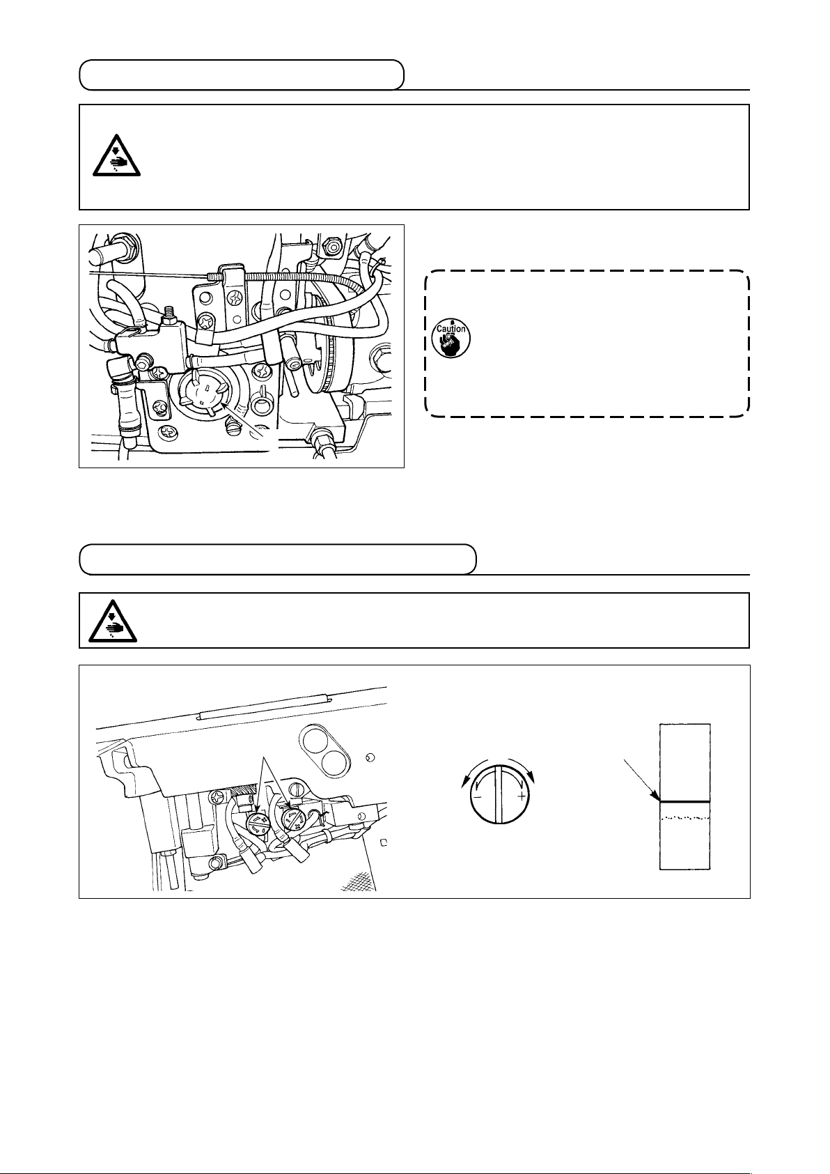
(2) Inclination
1) Remove cap 4 on the side of machine bed,
loosen feed bar shaft setscrew 3, and turn
knurled section 5 to adjust the inclination.
Standard inclination is the position where en-
graved marker dot A of feed bar arm aligns with
engraved marker dot B of feed bar shaft. (En-
graved marker dot C is not used.)
B
5
A
C
– 38 –
Page 41

6-7. Replacing the gauge
WARNING :
To protect against possible personal injury due to abrupt start of the machine, be sure to start the
following work after turning the power off and ascertaining that the motor is at rest.
Drive arm pin
2
7
A
6
2
9
Drive arm pin
1
B
2
8
2
6
9
3
3
4
5
• Move of the hook shaft saddle when replacing the gauge
1) Loosen screws No. 2 4 of hook driving shaft gears 3.
2) Align the needle with the blade point of hook.
3) Slightly loosen screws No. 1 5 of hook driving shaft gears 3 so that the screws does not come off the
at section of the hook driving shaft.
•
Loosen
four
setscrews 6 of connecting link (asm.) 9.
(Sewing machine with thread trimmer)
4) Loosen two setscrews 2 of hook shaft saddle 1, and move the hook shaft saddle.
(At this time, the hook driving shaft gears move as well.)
5) Set the clearance between the needle and the blade point of hook to 0.01 to 0.05 mm.
6) Tighten two setscrews 2 of the hook shaft saddle.
7) Tighten from screws No. 1 5 at the position where the clearance between hook driving shaft gears 3
and hook shaft saddles 1 is 0.5 mm. Then tighten screws No. 2 4.
• Make driving arms 7 and 8 come in contact with the driving arm pin in the directions of A and B
respectively and tighten four setscrews 6 in connecting link (asm.) 9. (Sewing machine with thread trim-
mer)
6-8. Adjusting the thread presser spring
WARNING :
To protect against possible personal injury due to abrupt start of the machine, be sure to start the
following work after turning the power off and ascertaining that the motor is at rest.
3
2
1
Insert a rod (thin rod, wrench, etc.) into adjusting
hole 2 in thread presser spring base 1, and loosen
A
setscrew 4 with a hexagonal wrench key of 1.5 mm.
Adjust the thread presser spring by moving rod 3 in
the direction of arrow mark A, and x it with setscrew
.
4
Clamp trouble occurs even when the
thread presser spring pressure is exces-
sive or insufcient. So, be careful.
4
– 39 –
Page 42

6-9. Adjusting the position of the moving knife
WARNING :
To protect against possible personal injury due to abrupt start of the machine, be sure to start the
following work after turning the power off and ascertaining that the motor is at rest.
1) Align counter knife base 1 with plane A of
counter knife 2.
2
A
1
2) Loosen clamp screw 5 in the rear of machine
bed and adjust so that the distances B and C
between the top end of moving knife 3 and the
center of needle 4 at the time of waiting become
the dimensions as shown in the list below when
the feed pitch is minimum and needle 4 is in the
lower dead point.
LH-3528A-7
LH-3568A-7
LH-3578A-7
LH-3588A-7
2
3
E
C B
4
D
2
3
Operator's
side
Left knife Right knife
Reference value)
B(D
6.2 (3.5) 7.5 (2.7)
7.3 (4.1) 8.9 (3.1)
Reference value)
C(E
6
5
3
D
5
3) Set clearance D between moving knife 3 and
protrusion 6 of the inner hook to 0.3 ± 0.1 mm.
Loosen moving knife setscrews 7 and 8, and
adjust the clearance.
7
8
– 40 –
Page 43

6-10. Position of the wiper
WARNING :
To protect against possible personal injury due to abrupt start of the machine, be sure to start the
following work after turning the power off and ascertaining that the motor is at rest.
1
3
Needle
5
4
1) Adjust engraved marker dot 1 on the machine arm to white marker dot 2 on the handwheel.
2) Move rod 3 in the direction of the arrow, and adjust with two clamping screws 5 so that the clearance
between the top end of needle and wiper 4 is approximately 2 mm.
2mm
2
6-11. Caution when installing the attachments
A
Be careful that screw A does not protrude in the
rear of the bed slide when xing the attachment to
the bed slide with the screw.
When it protrudes as shown in the gure,
the screw interferes with other compo-
nents and break-down will be caused.
– 41 –
Page 44

6-12. Replacing the bobbin thread slack preventer spring
(For LH-3568A,
1
3568A-7, 3588A and 3588A-7)
1) Loosen screw 1 and remove bobbin thread
slack preventer spring 2 from the groove on the
bobbin case.
2
Groove
2) Fit bobbin thread slack preventer spring 2 which
replaces the removed spring in the bobbin case
through the groove.
3) Fix bobbin thread slack preventer spring 2 in
the bobbin case by tighten screw 1. At this time,
carefully check the operating range and tension
or the spring.
6-13. Stop of the needle bars and angle of corners for corners stitching
(For LH-3568A, 3568A-7, 3588A and 3588A-7)
• Stop of the needle bar
When change lever 1 is moved to position L, the
left-hand needle bar stops, and when it is moved to
position R, the right-hand needle bar stops.
(3/16" gauge)
3 stitches
2
90˚
3 stitches
1
• When returning to 2-needle operation
Press change xing lever 2. Change lever 1 re-
turns to the position "0", and the machine returns to
2-needle sewing.
• Relation between the angle of corners and
stitch length
To perform corner stitching with accuracy, the stitch
length can be determined referring to the table of the
number of stitches by gauges.
However, check whether the stitch length determined
really matches the corner by actually sewing it.
(Example)
To sew a correr of 90˚ of angle using a 3/16" gauge
with the stitch length specied to 1.6mm, the number
of stiches can be obtained in the following way. Ob-
serve the "90˚" columns on the table of the number
of stitches by stitch length gauges to search for the
column in which "1.6" is indicated. Then, you can
nd "3" on the top of the "1.6" lines. This means the
number of stitches is 3.
• If sewing a corner of which angle is 40˚ or less, the thread take-up amount of the bobbin thread
slack preventer spring will be insufcient. In this case, the thread will remain on the wrong side
of the material.
• When performing the operation of changeover of separately driven needle bar, perform the
work after stopping the sewing machine once.
When the operation of changeover is performed at 1,000 sti/min or more, break-down will be
caused.)
• When the sewing machine is used as the substitute for 1-needle sewing machine in the state of
separately driven needle bar, break-down of the sewing machine will be caused. When performing sewing with 1-needle sewing machine, remove one of two needles and use the sewing
machine in the state that two needle bars operate.
– 42 –
Page 45

7. STITCH-TO-ANGLE TABLE BY GAUGE (PITCH AND mm CONVERSION TABLE)
1/8"(3.17mm)
Number of
stitches
1 2 3 4 5 6 7 8 9
Turning
angle
40 4.4 2.9 2.2 1.7 1.5
50 3.4 2.3 1.7
60 2.7 1.8
70 4.5 2.3 1.5
80 3.8 1.9
90 3.2 1.6
100 2.6
3/16"(4.76mm)
Number of
stitches
1 2 3 4 5 6 7 8 9
Turning
angle
40 3.3 2.6 2.2 1.9 1.6 1.5
50 3.4 2.6 2.0 1.7 1.5
60 2.7 2.1 1.6 1.4
70 3.4 2.3 1.7 1.4
80 2.8 1.9 1.4
90 4.8 2.4 1.6
100 4.0 2.0
1/4"(6.35mm)
Number of
stitches
1 2 3 4 5 6 7 8 9
Turning
angle
40 4.4 3.5 2.9 2.5 2.2 2.0
50 4.6 3.4 2.8 2.3 2.0 1.7 1.6
60 3.7 2.8 2.2 1.9 1.6
70 4.6 3.1 2.3 1.9 1.6
80 3.8 2.6 1.9 1.6
90 3.2 2.2 1.6
100 2.7 1.8
5/32"(3.96mm)
Number of
stitches
1 2 3 4 5 6 7 8 9
Turning
angle
40 3.6 2.7 2.2 1.8 1.6
50 4.2 2.8 2.1 1.7
60 3.4 2.3 1.7
70 2.8 1.9
80 4.7 2.4 1.6
90 4.0 2.0
100 3.3 1.7
7/32"(5.56mm)
Number of
stitches
1 2 3 4 5 6 7 8 9
Turning
angle
40 5.1 3.8 3.1 2.5 2.2 1.9 1.7
50 4.0 3.0 2.4 2.0 1.7 1.5
60 4.8 3.2 2.4 1.9 1.6
70 4.6 2.6 2.0 1.6
80 3.3 2.2 1.7
90 5.6 2.8 1.9 1.4
100 4.7 2.3 1.6
9/32"(7.14mm)
Number of
stitches
1 2 3 4 5 6 7 8 9
Turning
angle
40 4.9 3.9 3.3 2.8 2.5 2.2
50 5.1 3.8 3.1 2.6 2.2 1.9 1.7
60 4.1 3.1 2.5 2.1 1.8 1.5
70 5.1 3.4 2.5 2.0 1.7 1.5
80 4.3 2.8 2.1 1.7 1.4
90 3.6 2.4 1.8 1.4
100 3.0 2.0 1.5
5/16"(7.93mm)
Number of
stitches
1 2 3 4 5 6 7 8 9
Turning
angle
40 4.4 3.7 3.2 2.8 2.5
50 4.3 3.4 2.9 2.5 2.2 1.9
60 4.6 3.5 2.8 2.3 2.0 1.8 1.6
70 3.8 2.9 2.3 1.9 1.7 1.5
80 4.8 3.2 2.4 1.9 1.6
90 4.0 2.7 2.0 1.6
100 3.4 2.3 1.7
1/2"(12.7mm)
Number of
stitches
1 2 3 4 5 6 7 8 9
Turning
angle
40 5.8 5.0 4.4 3.9
50 5.5 4.5 3.9 3.4 3.0
60 5.5 4.4 3.7 3.1 2.8 2.4
70 4.5 3.6 3.0 2.6 2.3 2.0
80 5.1 3.8 3.1 2.5 2.2 1.9 1.7
90 4.2 3.2 2.5 2.1 1.8 1.6 1.4
100 5.3 3.6 2.7 2.1 1.8 1.5 1.3
3/8"(9.52mm)
Number of
stitches
1 2 3 4 5 6 7 8 9
Turning
angle
40 4.4 3.7 3.3 2.9
50 4.1 3.4 2.9 2.6 2.3
60 4.1 3.3 2.7 2.4 2.1 1.8
70 4.5 3.4 2.7 2.3 1.9 1.7
80 3.8 2.8 2.3 1.9 1.6
90 4.8 3.2 2.4 1.9 1.6
100 4.0 2.7 2.0 1.6
– 43 –
Page 46

2 2 6 - 4 7 1 5 0
2 2 6 - 4 7 3 5 8
5
S
A
C
4
F
1
3 2
1 6
D
3
3 2
E
7
1 6
W
7
3 2
G
9
1 6
H
5
8
K
3
T
1 -
U
2
L
1
M
N
P
Q
8
R
1
2 . 4
4 . 0
4 . 8
5 . 6
6 . 4
7 . 1
7 . 9
9 . 5
1 1 . 1
1 2 . 7
1 5 . 9
1 9 . 1
2 2 . 2
2 5 . 4
2 8 . 6
3 1 . 8
3 4 . 9
3 8 . 1
A
F
5
8
3
4
7
8
1
P a r t N o .
1 -
4
1
3
8
1 -
1
1 -
2
S
2 2 6 - 3 7 5 5 7
2 2 6 - 4 7 0 5 1
1
8
B
3 . 2
3
3 2
P a r t N o .
2 2 6 - 2 7 3 5 0
2 2 6 - 2 7 4 5 9
2 2 6 - 2 7 5 5 8
2 2 6 - 2 7 6 5 7
2 2 6 - 2 7 7 5 6
2 2 6 - 2 7 1 5 2
G
1 . 6 m m
3
1 -
5
3 2
S
1
8
3
A
C
4
F
1
3 2
1 6
D
3
3 2
E
7
1 6
W
7
3 2
G
9
1 6
H
5
8
K
3
4
T
1 -
1 -
U
2
L
1
M
N
P
Q
8
R
1
2 . 4
4 . 0
4 . 8
5 . 6
6 . 4
7 . 1
7 . 9
9 . 5
1 1 . 1
1 2 . 7
1 5 . 9
1 9 . 1
2 2 . 2
2 5 . 4
2 8 . 6
3 1 . 8
3 4 . 9
3 8 . 1
A
F
5
8
3
4
7
8
1
1
1 -
2
S
P a r t N o .
1
8
B
3 . 2
P a r t N o .
G
1 . 4 m m
0 . 9 m m
2 . 0 m m
2 2 6 - 3 7 6 5 6
2 2 6 - 3 7 7 5 5
2 2 6 - 3 7 8 5 4
2 2 6 - 3 8 0 5 0
2 2 6 - 3 8 2 5 8
2 2 6 - 3 8 3 5 7
2 2 6 - 3 8 4 5 6
2 2 6 - 3 8 7 5 3
2 2 6 - 3 8 9 5 1
2 2 6 - 3 9 1 5 7
2 2 6 - 3 9 2 5 6
2 2 6 - 3 9 3 5 5
2 2 6 - 3 9 4 5 4
2 2 6 - 4 7 4 5 7
2 2 6 - 4 7 5 5 6
2 2 6 - 4 7 2 5 9
4 0 0 - 3 5 8 9 6
P a r t N o .
2 2 6 - 4 1 9 5 5
2 2 6 - 4 1 8 5 6
2 2 6 - 4 1 7 5 7
2 2 6 - 4 1 6 5 8
2 2 6 - 4 1 4 5 0
2 2 6 - 4 1 2 5 2
2 2 6 - 4 0 9 5 7
2 2 6 - 4 0 8 5 8
2 2 6 - 4 0 7 5 9
2 2 6 - 4 0 5 5 1
2 2 6 - 4 0 3 5 3
4 0 0 - 3 5 8 9 7
2 . 4 m m
2 . 0 m m
2 2 6 - 4 0 4 5 2
2 2 6 - 4 1 0 5 4
2 2 6 - 4 1 3 5 1
2 2 6 - 4 2 0 5 2
2 2 6 - 4 2 1 5 1
2 2 8 - 1 6 5 5 7
2 2 8 - 1 6 7 5 5
2 2 8 - 1 6 9 5 3
2 2 8 - 1 7 0 5 0
4 0 0 - 3 3 9 4 7
4 0 0 - 3 3 9 5 3
4 0 0 - 3 3 9 4 1
P a r t N o . P a r t N o .
1 0 3 - 9 2 0 5 8
1 0 3 - 9 2 2 5 6
1 0 3 - 9 2 7 5 1
1 0 3 - 9 3 0 5 6
2 2 8 - 4 4 4 5 0
2 2 8 - 4 4 5 5 9
1 0 3 - 9 1 8 5 2
P a r t N o .
2 2 8 - 1 7 1 5 9
2 2 6 - 0 1 2 5 6
2 2 6 - 0 0 7 5 3
2 2 6 - 0 1 1 5 7 2 2 6 - 0 0 6 5 4
2 2 6 - 0 1 3 5 5 2 2 6 - 0 0 8 5 2
2 2 6 - 0 1 0 5 8 2 2 6 - 0 0 5 5 5
4 0 0 - 3 5 8 9 6
4 0 0 - 7 1 9 0 9
2 2 8 - 1 6 6 5 6
2 2 8 - 1 6 8 5 4
4 0 0 - 3 3 9 4 5
4 0 0 - 3 3 9 4 9
4 0 0 - 3 3 9 5 1
4 0 0 - 3 3 9 5 5
4 0 0 - 3 3 9 5 7
4 0 0 - 3 3 9 5 9
4 0 0 - 9 5 2 9 3
4 0 0 - 9 4 7 7 6
P a r t N o . P a r t N o .P a r t N o .
4 0 0 - 5 1 6 3 3
4 0 0 - 4 5 7 3 1
4 0 0 - 4 5 7 3 0
4 0 0 - 4 5 7 2 9
4 0 0 - 4 2 8 7 4 2 3 2 - 0 6 7 0 9
m m
m m
8. GAUGE SETS
(1) LH-3528A
Needle gauze size Presser foot asm.
Swivel guide
Presser foot asm.
Tip-divided Tip-divided Lower feed
Code
inch
Stitch spec.
Needle gauze size
Code
Lower
feed
Sliding plate asm.
(Left)
Sliding plate asm.
(Right)
Sliding plate asm.
(Left)
Option
Sliding plate asm. (Front)
(Tape attaching)
※ only
inch
Stitch spec.
Lower
feed
Spec. common Spec. common Spec. common Spec. common
– 44 –
(Tape attaching)
Page 47

5
S
A
C
4
F
1
3 2
1 6
D
3
3 2
E
7
1 6
W
7
3 2
G
9
1 6
H
5
8
K
3
T
1 -
U
2
L
1
M
N
P
Q
8
R
1
2 . 4
4 . 0
4 . 8
5 . 6
6 . 4
7 . 1
7 . 9
9 . 5
1 1 . 1
1 2 . 7
1 5 . 9
1 9 . 1
2 2 . 2
2 5 . 4
2 8 . 6
3 1 . 8
3 4 . 9
3 8 . 1
A
F
5
8
3
4
7
8
1
1 -
4
1
3
8
1 -
1
1 -
2
S
P a r t N o .
1
8
B
3 . 2
3
3 2
G
3 . 2 m m
2 . 2 m m
4 0 0 - 3 5 8 7 5
4 0 0 - 2 6 0 2 9
1 0 1 - 4 7 8 5 8
4 0 0 - 2 6 0 3 3
1 0 1 - 4 8 0 5 4
4 0 0 - 2 6 0 3 7
1 0 1 - 4 8 2 5 2
1 0 1 - 4 8 3 5 1
4 0 0 - 2 6 0 4 3
4 0 0 - 2 6 0 4 5
4 0 0 - 2 6 0 4 7
4 0 0 - 2 6 0 4 9
4 0 0 - 2 6 0 5 1
1 0 1 - 4 8 9 5 5
4 0 0 - 2 6 0 5 5
4 0 0 - 2 6 0 5 7
4 0 0 - 2 6 0 5 9
4 0 0 - 2 6 0 6 1
4 0 0 - 2 6 0 2 7
4 0 0 - 3 3 7 2 7
4 0 0 - 3 3 7 2 4
4 0 0 - 3 3 7 2 3
4 0 0 - 3 3 7 2 2
4 0 0 - 3 3 7 2 0
4 0 0 - 3 3 7 1 8
4 0 0 - 3 3 7 1 6
4 0 0 - 3 3 7 2 9
4 0 0 - 3 3 7 3 1
4 0 0 - 3 3 7 3 2
4 0 0 - 3 3 7 3 3
4 0 0 - 3 3 7 3 4
1 . 2
4 0 0 - 3 3 7 1 5
4 0 0 - 3 3 7 1 4
1 . 4
1 . 1 5
1 . 4
4 0 0 - 3 5 8 8 3
4 0 0 - 3 5 8 8 4
4 0 0 - 3 5 8 8 6
4 0 0 - 3 5 8 8 7
4 0 0 - 3 5 8 8 8
4 0 0 - 3 3 5 6 3
4 0 0 - 3 3 5 6 4
4 0 0 - 3 3 5 6 6
4 0 0 - 3 3 5 6 7
4 0 0 - 3 3 5 6 8
4 0 0 - 3 5 8 8 5 4 0 0 - 3 3 5 6 5
1 . 7
4 0 0 - 2 5 7 9 8
4 0 0 - 2 5 7 9 7
4 0 0 - 2 5 7 9 6
4 0 0 - 2 5 7 9 5
4 0 0 - 2 5 7 9 4
4 0 0 - 2 5 7 8 4
4 0 0 - 2 5 7 8 5
4 0 0 - 2 5 7 8 7
4 0 0 - 2 5 7 8 8
4 0 0 - 2 5 7 8 9
4 0 0 - 2 5 7 9 0
4 0 0 - 2 5 7 9 2
4 0 0 - 2 5 7 8 6
4 0 0 - 2 5 7 9 1
4 0 0 - 2 5 7 9 3
4 0 0 - 2 5 7 9 9
4 0 0 - 2 5 8 0 0
2 . 2
B 1 6 1 3 - 5 1 2 - R 0 H
B 1 6 1 3 - 5 1 2 - N 0 H
B 1 6 1 3 - 5 1 2 - D 0 H
B 1 6 1 3 - 5 1 2 - F 0 H
B 1 6 1 3 - 5 1 2 - H 0 H
B 1 6 1 3 - 5 1 2 - K 0 H
4 0 0 - 7 5 3 1 1
4 0 0 - 2 5 8 1 3
4 0 0 - 2 5 8 1 0
4 0 0 - 2 5 8 0 1
4 0 0 - 2 5 8 0 3
4 0 0 - 2 5 8 0 5
4 0 0 - 2 5 8 0 6
4 0 0 - 2 5 8 0 7
2 3 2 - 0 5 3 0 5
2 3 2 - 0 5 5 0 3
2 2 8 - 4 8 1 0 5
2 2 8 - 4 8 4 0 2
2 2 8 - 4 8 5 0 1
2 3 2 - 0 5 1 0 7
2 2 8 - 4 8 3 0 3
1 . 7
1 . 7
1 . 7
1 . 7
.oNtraP.oNtraP.oNtraP .oNtraP.oNtraP.oNtraP
3
1 -
5
3 2
S
1
8
3
A
C
4
F
1
3 2
1 6
D
3
3 2
E
7
1 6
W
7
3 2
G
9
1 6
H
5
8
K
3
4
T
1 -
1 -
U
2
L
1
M
N
P
Q
8
R
1
2 . 4
4 . 0
4 . 8
5 . 6
6 . 4
7 . 1
7 . 9
9 . 5
1 1 . 1
1 2 . 7
1 5 . 9
1 9 . 1
2 2 . 2
2 5 . 4
2 8 . 6
3 1 . 8
3 4 . 9
3 8 . 1
A
F
m m
5
8
3
4
7
8
1
1
1 -
2
S
.oNtraP.oNtraP.oNtraP P a r t N o .
1
8
B
3 . 2
P a r t N o .
G
P a r t N o .P a r t N o .
2 2 6 - 3 0 2 0 6
2 2 6 - 3 0 4 0 4
2 2 6 - 3 0 5 0 3
2 2 6 - 3 0 6 0 2
2 2 6 - 3 0 8 0 0
2 2 6 - 3 0 9 0 9
2 2 6 - 3 1 0 0 6
2 2 6 - 3 1 1 0 5
2 2 6 - 3 1 3 0 3
2 2 6 - 3 1 4 0 2
2 2 6 - 3 1 5 0 1
2 2 6 - 3 1 7 0 9
2 2 6 - 3 1 8 0 8
2 2 6 - 3 1 9 0 7
2 2 6 - 3 2 0 0 4
2 2 6 - 3 2 1 0 3
2 2 6 - 3 2 2 0 2
1 . 9
1 . 7
4 0 0 - 3 3 5 6 3
4 0 0 - 2 5 8 0 2
4 0 0 - 2 5 8 0 4
4 0 0 - 2 5 8 0 8
4 0 0 - 2 5 8 0 9
4 0 0 - 2 5 8 1 1
4 0 0 - 2 5 8 1 2
4 0 0 - 2 5 8 1 4
4 0 0 - 2 5 8 1 5
4 0 0 - 2 5 8 1 6
B 1 6 1 3 - 5 1 2 - E 0 H
B 1 6 1 3 - 5 1 2 - G 0 H
B 1 6 1 3 - 5 1 2 - L 0 H
B 1 6 1 3 - 5 1 2 - M 0 H
B 1 6 1 3 - 5 1 2 - P 0 H
B 1 6 1 3 - 5 1 2 - Q 0 H
B 1 6 1 3 - 5 1 2 - S 0 H
B 1 6 1 3 - 5 1 2 - T 0 H
B 1 6 1 3 - 5 1 2 - U 0 H
P a r t N o .
1 0 1 - 4 7 5 5 1
1 0 1 - 4 7 6 5 0
1 0 1 - 4 7 7 5 9
1 0 1 - 4 7 8 5 8
1 0 1 - 4 7 9 5 7
1 0 1 - 4 8 0 5 4
1 0 1 - 4 8 1 5 3
1 0 1 - 4 8 2 5 2
1 0 1 - 4 8 3 5 1
1 0 1 - 4 8 4 5 0
1 0 1 - 4 8 5 5 9
1 0 1 - 4 8 6 5 8
1 0 1 - 4 8 7 5 7
1 0 1 - 4 8 8 5 6
1 0 1 - 4 8 9 5 5
1 0 1 - 4 9 0 5 2
1 0 1 - 4 9 1 5 1
1 0 1 - 4 9 2 5 0
1 0 1 - 4 9 3 5 9
2 2 6 - 2 8 0 0 2
2 2 6 - 2 8 6 0 6
2 2 6 - 2 8 5 0 7
2 2 6 - 2 8 4 0 8
2 2 6 - 2 8 3 0 9
2 2 6 - 2 8 2 0 0
2 2 6 - 2 5 1 0 7
2 2 8 - 4 5 2 0 0
2 2 6 - 2 6 8 0 8
2 2 6 - 2 6 7 0 9
2 2 6 - 2 6 6 0 0
2 2 6 - 2 6 5 0 1
2 2 6 - 2 6 4 0 2
2 2 6 - 2 6 3 0 3
2 2 6 - 2 6 2 0 4
2 2 6 - 2 6 1 0 5
2 2 6 - 2 6 0 0 6
2 2 6 - 2 5 9 0 9
2 2 6 - 2 5 8 0 0
2 2 6 - 2 5 7 0 1
2 2 6 - 2 5 6 0 2
2 2 6 - 2 5 5 0 3
2 2 6 - 2 5 4 0 4
2 2 6 - 2 5 3 0 5
2 2 6 - 2 5 2 0 6
2 2 6 - 2 5 0 0 8
4 0 0 - 6 2 2 5 8
4 0 0 - 6 2 2 5 7
4 0 0 - 6 2 2 5 6
4 0 0 - 6 2 2 5 4
2 2 8 - 4 5 6 0 6
2 2 8 - 4 5 4 0 8
2 2 6 - 2 8 1 0 1
B 1 6 1 3 - 5 1 2 - B 0 H
B 1 6 1 3 - 5 1 2 - C 0 H
4 0 0 - 6 2 2 4 9
4 0 0 - 6 2 2 5 1
4 0 0 - 6 2 2 5 2
4 0 0 - 6 2 2 5 3
4 0 0 - 9 5 2 8 8
4 0 0 - 9 4 7 7 2
m m
Needle gauze size Feed dog
Code
inch
Option Option Option
Throat Plate
(with taping)
Stitch spec.
Needle gauze size Feed dog (Lower feed) Needle clamp asm. Throat Plate
Code
inch
Wire type Hole type
Throat Plate (Lower feed)
Stitch spec.
Lower
feed
– 45 –
※ only
Spec. common
Page 48

5
S
C
4
F
1
3 2
1 6
D
3
3 2
E
7
1 6
W
7
3 2
G
9
1 6
H
5
8
K
3
1 -
2
L
1
M
N
P
Q
8
R
1
4 . 0
4 . 8
5 . 6
6 . 4
7 . 1
7 . 9
9 . 5
1 1 . 1
1 2 . 7
1 5 . 9
1 9 . 1
2 2 . 2
2 5 . 4
2 8 . 6
3 1 . 8
5
8
3
4
7
8
1
1 -
4
1
S
P a r t N o .
1
8
B
3 . 2
G
P a r t N o .P a r t N o .
5
S
1
C
4
F
1
3 2
1 6
D
3
3 2
E
7
1 6
W
7
3 2
G
9
1 6
H
5
8
K
3
4
1 -
1 -
2
L
1
M
N
P
Q
8
R
1
4 . 0
4 . 8
5 . 6
6 . 4
7 . 1
7 . 9
9 . 5
1 1 . 1
1 2 . 7
1 5 . 9
1 9 . 1
2 2 . 2
2 5 . 4
2 8 . 6
3 1 . 8
5
8
3
4
7
8
1
S
P a r t N o .
4 0 0 - 2 5 4 8 5
4 0 0 - 2 5 4 9 0
4 0 0 - 2 5 4 9 1
4 0 0 - 2 5 4 9 2
4 0 0 - 2 5 4 9 3
4 0 0 - 2 5 4 9 4
4 0 0 - 2 5 4 9 5
4 0 0 - 2 5 4 9 8
4 0 0 - 2 5 4 9 9
4 0 0 - 2 5 5 0 0
4 0 0 - 2 5 5 0 2
4 0 0 - 2 5 5 0 3
4 0 0 - 2 5 5 0 4
4 0 0 - 2 5 5 0 5
1
8
B
3 . 2
4 0 0 - 3 5 8 8 1
G
4 0 0 - 3 5 8 9 6
P a r t N o .
2 2 6 - 4 1 9 5 5
2 2 6 - 4 1 8 5 6
2 2 6 - 4 1 7 5 7
2 2 6 - 4 1 6 5 8
2 2 6 - 4 1 4 5 0
2 2 6 - 4 1 2 5 2
2 2 6 - 4 0 9 5 7
2 2 6 - 4 0 8 5 8
2 2 6 - 4 0 7 5 9
2 2 6 - 4 0 5 5 1
2 2 6 - 4 0 3 5 3
4 0 0 - 3 5 8 9 7
2 . 4 m m
2 . 0 m m
2 2 6 - 4 0 4 5 2
2 2 6 - 4 1 3 5 1
2 2 8 - 1 6 5 5 7
2 2 8 - 1 6 7 5 5
4 0 0 - 3 5 8 9 0
4 0 0 - 2 5 8 1 7
4 0 0 - 2 5 8 1 8
4 0 0 - 2 5 8 1 9
4 0 0 - 2 6 7 1 5
4 0 0 - 2 5 8 2 0
4 0 0 - 2 5 8 2 1
4 0 0 - 2 5 8 2 2
4 0 0 - 2 5 8 2 4
4 0 0 - 2 5 8 2 5
4 0 0 - 2 5 8 2 6
4 0 0 - 2 5 8 2 7
4 0 0 - 2 5 8 2 8
4 0 0 - 2 5 8 2 9
4 0 0 - 2 5 8 3 0
4 0 0 - 2 5 8 3 1
4 0 0 - 2 5 8 3 3
4 0 0 - 2 5 8 3 8
P a r t N o .
4 0 0 - 3 5 8 9 1
4 0 0 - 3 5 8 9 2
4 0 0 - 3 5 8 9 4
2 . 4
2 2 8 - 1 7 1 5 9
P a r t N o .
4 0 0 - 2 5 2 4 7 4 0 0 - 2 5 2 3 5
4 0 0 - 2 5 2 4 8 4 0 0 - 2 5 2 3 6
4 0 0 - 2 5 2 3 94 0 0 - 2 5 2 4 9
4 0 0 - 2 5 2 5 0 4 0 0 - 2 5 2 4 0
P a r t N o .
1 . 7
3 . 2 m m
2 . 2 m m
1 . 7
1 . 7
1 . 7
32852-00469452-004
4 0 0 - 5 0 0 0 9
4 0 0 - 5 0 0 1 0
4 0 0 - 5 0 0 1 1
4 0 0 - 3 5 8 9 3
4 0 0 - 7 1 9 1 2
4 0 0 - 3 5 8 9 5
4 0 0 - 7 1 9 1 3
4 0 0 - 7 1 9 1 4
4 0 0 - 7 1 9 1 5
4 0 0 - 7 1 9 1 6
4 0 0 - 2 5 8 3 2
4 0 0 - 2 5 8 3 4
4 0 0 - 2 5 8 3 5
4 0 0 - 2 5 8 3 6
4 0 0 - 2 5 8 3 7
4 0 0 - 2 5 8 3 9
4 0 0 - 2 5 8 4 0
4 0 0 - 2 5 8 4 1
4 0 0 - 2 5 8 4 2
4 0 0 - 2 5 8 4 3
4 0 0 - 2 5 8 4 4
2 2 6 - 4 1 0 5 4 4 0 0 - 3 3 9 4 1
2 2 8 - 1 7 0 5 0
2 2 8 - 1 6 9 5 3
1 . 7
1 . 9
P a r t N o .
4 0 0 - 6 1 2 7 0
4 0 0 - 6 1 2 7 1
4 0 0 - 6 1 2 7 2
4 0 0 - 6 1 2 7 3
4 0 0 - 6 1 2 7 4
4 0 0 - 6 1 2 7 5
4 0 0 - 6 1 2 7 6
4 0 0 - 6 1 2 7 7
4 0 0 - 6 1 2 7 8
4 0 0 - 6 1 2 7 9
4 0 0 - 6 1 2 8 0
4 0 0 - 6 1 2 8 1
4 0 0 - 6 1 2 8 2
4 0 0 - 6 1 2 8 3
4 0 0 - 6 1 2 8 4
4 0 0 - 3 5 8 9 6
4 0 0 - 7 1 9 0 9
2 2 8 - 1 6 6 5 6
2 2 8 - 1 6 8 5 4
4 0 0 - 3 3 9 4 5
4 0 0 - 3 3 9 4 7
4 0 0 - 3 3 9 4 9
4 0 0 - 3 3 9 5 1
4 0 0 - 3 3 9 5 3
4 0 0 - 3 3 9 5 5
4 0 0 - 5 3 7 0 54 0 0 - 5 3 7 0 5
4 0 0 - 7 1 9 1 1
4 0 0 - 2 6 0 2 7
4 0 0 - 2 6 0 6 1
4 0 0 - 2 6 0 5 9
4 0 0 - 2 6 0 5 7
4 0 0 - 2 6 0 5 5
4 0 0 - 2 6 0 5 1
4 0 0 - 2 6 0 4 9
4 0 0 - 2 6 0 4 7
4 0 0 - 2 6 0 4 5
4 0 0 - 2 6 0 4 3
1 0 1 - 4 8 3 5 1
4 0 0 - 2 6 0 3 7
1 0 1 - 4 8 0 5 4
4 0 0 - 2 6 0 3 3
1 0 1 - 4 7 8 5 8
4 0 0 - 2 6 0 2 9
4 0 0 - 3 5 8 7 5
P a r t N o . P a r t N o .
1 0 1 - 4 7 5 5 1
1 0 1 - 4 7 6 5 0
1 0 1 - 4 7 7 5 9
1 0 1 - 4 7 8 5 8
1 0 1 - 4 7 9 5 7
1 0 1 - 4 8 0 5 4
1 0 1 - 4 8 1 5 3
1 0 1 - 4 8 2 5 2
1 0 1 - 4 8 3 5 1
1 0 1 - 4 8 4 5 0
1 0 1 - 4 8 5 5 9
1 0 1 - 4 8 6 5 8
1 0 1 - 4 8 7 5 7
1 0 1 - 4 8 8 5 6
1 0 1 - 4 8 9 5 5
1 0 1 - 4 9 0 5 2
1 0 1 - 4 9 1 5 1
1 0 1 - 4 9 2 5 0
1 0 1 - 4 9 3 5 9
3
1 -
8
T
U
3 4 . 9
3 8 . 1
A
F
1
1 -
2
A
2 . 4
3 2
3
4 0 0 - 9 5 2 8 9
4 0 0 - 9 4 7 7 3
4 0 0 - 9 5 2 9 3
4 0 0 - 9 4 7 7 6
P a r t N o .
4 0 0 - 4 2 8 8 0
P a r t N o .
4 0 0 - 4 5 7 2 9
4 0 0 - 4 5 7 3 0
4 0 0 - 4 5 7 3 1
4 0 0 - 5 1 6 3 3
P a r t N o .
m m
m m
(2) LH-3528A-7
Needle gauze size
Throat Plate
Needle clamp asm. Feed dog
Code
Wire type Hole type
Option
Option
inch
Stitch spec.
Needle gauze size Presser foot asm.
Code
inch
※ only
Tip-divided Tip-divided
Swivel guide
Presser foot asm.
Sliding plate asm.
(Left)
Sliding plate asm.
(Right)
Sliding plate asm.
Option
(Left)
Sliding plate asm.
(Front)
Stitch spec. Spec. common Spec. common Spec. common Spec. common
– 46 –
Page 49

(3) LH-3568A
5
C
4
F
1
3 2
1 6
D
3
3 2
E
7
3 2
G
9
1 6
H
5
8
K
3
2
L
1
M
N
4 . 0
4 . 8
5 . 6
6 . 4
7 . 1
7 . 9
9 . 5
1 2 . 7
1 5 . 9
1 9 . 1
5
8
3
4
S
P a r t N o .
1
8
B
3 . 2
G
5
C
4
F
1
3 2
1 6
D
3
3 2
E
7
3 2
G
9
1 6
H
5
8
K
3
2
L
1
M
N
4 . 0
4 . 8
5 . 6
6 . 4
7 . 1
7 . 9
9 . 5
1 2 . 7
1 5 . 9
1 9 . 1
5
8
3
4
S
1
8
B
3 . 2
P a r t N o .
G
2 . 4 m m
2 . 0 m m
P a r t N o .
4 0 0 - 3 5 7 6 1
4 0 0 - 3 5 7 7 0
4 0 0 - 3 5 7 6 9
4 0 0 - 3 5 7 6 8
4 0 0 - 3 5 7 6 6
4 0 0 - 3 5 7 6 2
P a r t N o .
4 0 0 - 3 5 7 7 2
4 0 0 - 3 5 7 7 5
4 0 0 - 3 5 7 7 6
4 0 0 - 3 5 7 7 8
4 0 0 - 3 5 7 7 9
4 0 0 - 3 5 7 7 1
4 0 0 - 3 5 7 8 0
4 0 0 - 2 6 0 9 0
4 0 0 - 2 6 0 8 8
4 0 0 - 2 6 0 8 6
4 0 0 - 2 6 0 8 44 0 0 - 2 6 0 6 3
4 0 0 - 2 6 0 6 5
4 0 0 - 2 6 0 6 7
4 0 0 - 2 6 0 9 5
4 0 0 - 2 6 0 9 1
4 0 0 - 2 6 0 6 9
4 0 0 - 2 6 0 7 0
4 0 0 - 3 5 8 7 8
4 0 0 - 2 6 0 7 2 4 0 0 - 2 6 0 9 3
4 0 0 - 2 6 0 7 4
4 0 0 - 2 6 0 7 6
4 0 0 - 2 6 0 7 8
4 0 0 - 3 5 8 7 7
4 0 0 - 2 6 0 9 9
4 0 0 - 2 6 0 9 7
4 0 0 - 2 6 1 0 14 0 0 - 2 6 0 8 0
P a r t N o .
3 . 2 m m
2 . 2 m m
P a r t N o . P a r t N o .
5
C
4
F
1
3 2
1 6
D
3
3 2
E
7
3 2
G
9
1 6
H
5
8
K
3
2
L
1
M
N
4 . 0
4 . 8
5 . 6
6 . 4
7 . 1
7 . 9
9 . 5
1 2 . 7
1 5 . 9
1 9 . 1
5
8
3
4
S
1
8
B
3 . 2
G
P a r t N o .
2 2 6 - 0 1 0 5 8
2 2 6 - 0 1 1 5 7
P a r t N o .
2 2 6 - 0 0 5 5 5
2 2 6 - 0 0 6 5 4
1 . 9
1 . 7
1 . 7
1 . 7
4 0 0 - 4 2 8 7 4
P a r t N o .
2 . 2
P a r t N o .
1 . 7
1 . 7
P
Q
2 2 . 2
2 5 . 4
7
8
1
4 0 0 - 2 5 7 9 6
4 0 0 - 2 5 7 9 5
4 0 0 - 2 5 7 9 4
4 0 0 - 2 5 7 8 4
4 0 0 - 2 5 7 8 5
4 0 0 - 2 5 7 8 7
4 0 0 - 2 5 7 8 8
4 0 0 - 2 5 7 8 9
4 0 0 - 2 5 7 9 0
4 0 0 - 2 5 7 9 2
4 0 0 - 2 5 7 8 6
4 0 0 - 2 5 7 9 3
B 1 6 1 3 - 5 1 2 - N 0 H
B 1 6 1 3 - 5 1 2 - D 0 H
B 1 6 1 3 - 5 1 2 - F 0 H
B 1 6 1 3 - 5 1 2 - H 0 H
B 1 6 1 3 - 5 1 2 - K 0 H
4 0 0 - 2 5 8 1 0
4 0 0 - 2 5 8 0 1
4 0 0 - 2 5 8 0 3
4 0 0 - 2 5 8 0 5
4 0 0 - 2 5 8 0 6
P
Q
2 2 . 2
2 5 . 4
7
8
1
2 2 6 - 3 0 2 0 6
2 2 6 - 3 0 4 0 4
2 2 6 - 3 0 5 0 3
2 2 6 - 3 0 6 0 2
2 2 6 - 3 0 8 0 0
2 2 6 - 3 0 9 0 9
2 2 6 - 3 1 0 0 6
2 2 6 - 3 1 3 0 3
2 2 6 - 3 1 4 0 2
2 2 6 - 3 1 5 0 1
2 2 6 - 3 1 7 0 9
2 2 6 - 3 1 8 0 8
4 0 0 - 3 3 5 6 3
4 0 0 - 2 5 8 0 2
4 0 0 - 2 5 8 0 4
4 0 0 - 2 5 8 0 8
4 0 0 - 2 5 8 0 9
4 0 0 - 2 5 8 1 1
4 0 0 - 2 5 8 1 2
B 1 6 1 3 - 5 1 2 - E 0 H
B 1 6 1 3 - 5 1 2 - G 0 H
B 1 6 1 3 - 5 1 2 - L 0 H
B 1 6 1 3 - 5 1 2 - M 0 H
B 1 6 1 3 - 5 1 2 - P 0 H
B 1 6 1 3 - 5 1 2 - Q 0 H
4 0 0 - 3 5 8 9 7
2 2 6 - 4 0 3 5 3
2 2 6 - 4 0 5 5 1
2 2 6 - 4 0 7 5 9
2 2 6 - 4 0 8 5 8
2 2 6 - 4 0 9 5 7
2 2 6 - 4 1 2 5 2
2 2 6 - 4 1 4 5 0
2 2 6 - 4 1 6 5 8
2 2 6 - 4 1 7 5 7
2 2 6 - 4 0 4 5 2
4 0 0 - 3 5 8 9 6
2 2 8 - 1 6 5 5 7
2 2 8 - 1 6 7 5 5
2 2 8 - 1 6 9 5 3
2 2 8 - 1 7 0 5 0
4 0 0 - 3 3 9 4 7
2 2 6 - 4 1 3 5 1
2 2 8 - 1 7 1 5 9
Q
1
2 5 . 4
4 0 0 - 2 6 0 8 2 4 0 0 - 2 6 1 0 3
P a r t N o . P a r t N o .
B 1 4 0 2 - 5 2 8 - B A 0 - A
B 1 4 0 2 - 5 2 8 - C A 0 - A
B 1 4 0 2 - 5 2 8 - D A L - A
B 1 4 0 2 - 5 2 8 - E A L
B 1 4 0 2 - 5 2 8 - F A L - A
B 1 4 0 2 - 5 2 8 - G A L
B 1 4 0 2 - 5 2 8 - H A L - A
B 1 4 0 2 - 5 2 8 - K A L - A
B 1 4 0 2 - 5 2 8 - L A L
B 1 4 0 2 - 5 2 8 - M A L
B 1 4 0 2 - 5 2 8 - N A L
B 1 4 0 2 - 5 2 8 - Q A L B 1 4 0 2 - 5 2 8 - Q A R
B 1 4 0 2 - 5 2 8 - N A R
B 1 4 0 2 - 5 2 8 - M A R
B 1 4 0 2 - 5 2 8 - L A R
B 1 4 0 2 - 5 2 8 - K A R - A
B 1 4 0 2 - 5 2 8 - H A R - A
B 1 4 0 2 - 5 2 8 - G A R
B 1 4 0 2 - 5 2 8 - F A R - A
B 1 4 0 2 - 5 2 8 - E A R
B 1 4 0 2 - 5 2 8 - D A R - A
B 1 4 0 2 - 5 2 8 - C A 0 - A
B 1 4 0 2 - 5 2 8 - B A 0 - A
2 2 6 - 0 0 7 5 32 2 6 - 0 1 2 5 6
4 0 0 - 5 1 6 3 3
4 0 0 - 4 5 7 2 9
P a r t N o .
B 1 6 1 3 - 5 1 2 - C 0 H
4 0 0 - 3 5 8 9 6
4 0 0 - 7 1 9 0 9
2 2 8 - 1 6 6 5 6
2 2 8 - 1 6 8 5 4
4 0 0 - 3 3 9 4 5
4 0 0 - 3 3 9 4 9
4 0 0 - 3 3 9 5 1
4 0 0 - 4 5 7 3 0
1 0 2 - 2 9 1 6 9
B 1 4 0 2 - 5 2 6 - G A R - A
1 0 2 - 2 8 5 6 7
B 1 4 0 2 - 5 2 6 - D A R - A
B 1 4 0 2 - 5 2 6 - C A 0 - A
1 0 2 - 2 9 1 5 1
1 0 2 - 2 8 9 5 5
1 0 2 - 2 8 8 5 6
B 1 4 0 2 - 5 2 6 - K A R - A
B 1 4 0 2 - 5 2 6 - F A R - A
B 1 4 0 2 - 5 2 6 - L A L - A
B 1 4 0 2 - 5 2 6 - K A L - A
B 1 4 0 2 - 5 2 6 - B A 0 - A
B 1 4 0 2 - 5 2 6 - H A L - A B 1 4 0 2 - 5 2 6 - H A R - A
B 1 4 0 2 - 5 2 6 - G A L - A
B 1 4 0 2 - 5 2 6 - F A L - A
1 0 2 - 2 8 5 5 9
B 1 4 0 2 - 5 2 6 - B A 0 - A
1 0 2 - 2 8 8 6 4
B 1 4 0 2 - 5 2 6 - L A R - A
1 0 2 - 2 8 9 6 3
B 1 4 0 2 - 5 2 6 - D A L - A
B 1 4 0 2 - 5 2 6 - C A 0 - A
2 2 6 - 2 5 1 0 7
2 2 6 - 2 6 2 0 4
2 2 6 - 2 6 1 0 5
2 2 6 - 2 6 0 0 6
2 2 6 - 2 5 8 0 0
2 2 6 - 2 5 7 0 1
2 2 6 - 2 5 6 0 2
2 2 6 - 2 5 5 0 3
2 2 6 - 2 5 4 0 4
2 2 6 - 2 5 3 0 5
2 2 6 - 2 5 2 0 6
2 2 6 - 2 6 4 0 2
2 2 6 - 2 6 3 0 3
P a r t N o .
4 0 0 - 7 2 3 3 8
P a r t N o .P a r t N o .P a r t N o .P a r t N o .
P
7
8
2 2 . 2 4 0 0 - 7 1 9 1 7
4 0 0 - 7 1 9 2 1
4 0 0 - 7 1 9 1 9
4 0 0 - 7 1 9 2 3
B 1 4 0 2 - 5 2 8 - P A L B 1 4 0 2 - 5 2 8 - P A R
A-RAD-825-2041BA-LAD-825-2041B
B 1 4 0 2 - 5 2 8 - E A L B 1 4 0 2 - 5 2 8 - E A R
B 14 0 2 - 5 2 8 - F A L -A B 1 4 0 2- 5 2 8 - F A R - A
4 0 0 - 3 5 7 6 5
B 1 40 2 - 5 2 8 - K A L - A B 1 4 0 2- 5 2 8 - K A R - A
4 0 0 - 9 4 7 7 6
4 0 0 - 9 5 2 9 3
4 0 0 - 9 5 2 8 8
4 0 0 - 9 4 7 7 2
P a r t N o .
m m
m m
m m
Needle gauze size
Code
Needle clamp asm.
(Left)
Needle clamp asm.
(Right)
Option Option
Needle clamp asm. (DP5)
Needle clamp asm.
(Left)
Hole type
Needle clamp asm.
(Right)
Hole type
Sliding plate asm.
(Left)
Option
Sliding plate asm.
(Front)
inch
Stitch spec.
Needle gauze size
Code
inch
Needle clamp
asm. (Left)
Option Option Option Option
Needle clamp asm. (DP17)
Needle clamp
asm.
(Right)
Needle clamp asm.
(Left)
Needle clamp asm.
(Right)
Throat Plate
Sliding plate
asm. (Left)
Sliding plate
asm. (Right)
Stitch spec.
Needle gauze size
Code
inch
Feed dog
Option
Stitch spec.
– 47 –
Option
※ only
Presser foot asm.
Tip-divided Tip-divided
Swivel guide
Presser foot asm.
Page 50

5
C
4
F
1
3 2
1 6
D
3
3 2
E
7
3 2
G
9
1 6
H
5
8
K
3
2
L
1
M
N
4 . 0
4 . 8
5 . 6
6 . 4
7 . 1
7 . 9
9 . 5
1 2 . 7
1 5 . 9
1 9 . 1
m m
5
8
3
4
S
P a r t N o .
1
8
B
3 . 2
G
5
C
4
F
1
3 2
1 6
D
3
3 2
E
7
3 2
G
9
1 6
H
5
8
K
3
2
L
1
M
N
4 . 0
4 . 8
5 . 6
6 . 4
7 . 1
7 . 9
9 . 5
1 2 . 7
1 5 . 9
1 9 . 1
5
8
3
4
S
1
8
B
3 . 2
P a r t N o .
G
2 . 4 m m
2 . 0 m m
P a r t N o .
4 0 0 - 3 5 7 6 1
4 0 0 - 3 5 7 7 0
4 0 0 - 3 5 7 6 9
4 0 0 - 3 5 7 6 8
4 0 0 - 3 5 7 6 6
4 0 0 - 3 5 7 6 5
4 0 0 - 3 5 7 6 2
P a r t N o .
4 0 0 - 3 5 7 7 2
4 0 0 - 3 5 7 7 5
4 0 0 - 3 5 7 7 6
4 0 0 - 3 5 7 7 8
4 0 0 - 3 5 7 7 9
4 0 0 - 3 5 7 7 1
4 0 0 - 3 5 7 8 0
4 0 0 - 2 6 0 9 0
4 0 0 - 2 6 0 8 8
4 0 0 - 2 6 0 8 6
4 0 0 - 2 6 0 8 44 0 0 - 2 6 0 6 3
4 0 0 - 2 6 0 6 5
4 0 0 - 2 6 0 6 7
4 0 0 - 2 6 0 9 5
4 0 0 - 2 6 0 9 1
4 0 0 - 2 6 0 6 9
4 0 0 - 2 6 0 7 0
4 0 0 - 3 5 8 7 8
4 0 0 - 2 6 0 7 2 4 0 0 - 2 6 0 9 3
4 0 0 - 2 6 0 7 4
4 0 0 - 2 6 0 7 6
4 0 0 - 2 6 0 7 8
4 0 0 - 3 5 8 7 7
4 0 0 - 2 6 0 9 9
4 0 0 - 2 6 0 9 7
4 0 0 - 2 6 1 0 14 0 0 - 2 6 0 8 0
P a r t N o .
3 . 2 m m
2 . 2 m m
P a r t N o . P a r t N o .
5
C
4
F
1
3 2
1 6
D
3
3 2
E
7
3 2
G
9
1 6
H
5
8
K
3
2
L
1
M
N
4 . 0
4 . 8
5 . 6
6 . 4
7 . 1
7 . 9
9 . 5
1 2 . 7
1 5 . 9
1 9 . 1
5
8
3
4
S
1
8
B
3 . 2
G
P a r t N o .
4 0 0 - 2 5 2 4 7
4 0 0 - 2 5 2 4 8
P a r t N o .
4 0 0 - 2 5 2 3 5
4 0 0 - 2 5 2 3 6
1 . 9
1 . 7
1 . 7
1 . 7
4 0 0 - 4 2 8 8 0
2 . 4
P a r t N o .
1 . 7
1 . 7
P
Q
2 2 . 2
2 5 . 4
7
8
1
4 0 0 - 2 5 8 2 8
4 0 0 - 2 5 8 2 6
4 0 0 - 2 5 8 1 7
4 0 0 - 2 5 8 1 8
4 0 0 - 2 6 7 1 5
4 0 0 - 2 5 8 2 0
4 0 0 - 2 5 8 2 1
4 0 0 - 2 5 8 2 2
4 0 0 - 2 5 8 2 4
4 0 0 - 2 5 8 1 9
4 0 0 - 2 5 8 2 5
4 0 0 - 3 5 8 9 5
4 0 0 - 3 5 8 9 1
4 0 0 - 3 5 8 9 2
4 0 0 - 5 0 0 1 1
4 0 0 - 3 5 8 9 3
4 0 0 - 2 5 8 4 0
4 0 0 - 2 5 8 3 1
4 0 0 - 2 5 8 3 3
4 0 0 - 2 5 8 3 5
4 0 0 - 2 5 8 3 6
P
Q
2 2 . 2
2 5 . 4
7
8
1
4 0 0 - 6 1 2 7 0
4 0 0 - 6 1 2 7 1
4 0 0 - 6 1 2 7 2
4 0 0 - 6 1 2 7 3
4 0 0 - 6 1 2 7 4
4 0 0 - 6 1 2 7 5
4 0 0 - 6 1 2 7 6
4 0 0 - 6 1 2 7 7
4 0 0 - 6 1 2 7 8
4 0 0 - 6 1 2 7 9
4 0 0 - 6 1 2 8 0
4 0 0 - 6 1 2 8 1
4 0 0 - 6 1 2 8 2
4 0 0 - 3 5 8 9 0
4 0 0 - 2 5 8 3 2
4 0 0 - 2 5 8 3 4
4 0 0 - 2 5 8 3 8
4 0 0 - 2 5 8 3 9
4 0 0 - 5 0 0 0 9
4 0 0 - 5 0 0 1 0
4 0 0 - 3 5 8 9 4
4 0 0 - 3 5 8 9 7
2 2 6 - 4 0 3 5 3
2 2 6 - 4 0 5 5 1
2 2 6 - 4 0 7 5 9
2 2 6 - 4 0 8 5 8
2 2 6 - 4 0 9 5 7
2 2 6 - 4 1 2 5 2
2 2 6 - 4 1 4 5 0
2 2 6 - 4 1 6 5 8
2 2 6 - 4 1 7 5 7
2 2 6 - 4 0 4 5 2
4 0 0 - 3 5 8 9 6
2 2 8 - 1 6 5 5 7
2 2 8 - 1 6 7 5 5
2 2 8 - 1 6 9 5 3
2 2 8 - 1 7 0 5 0
4 0 0 - 3 3 9 4 7
2 2 6 - 4 1 3 5 1
2 2 8 - 1 7 1 5 9
P a r t N o . P a r t N o .
B 1 4 0 2 - 5 2 8 - B A 0 - A
B 1 4 0 2 - 5 2 8 - C A 0 - A
B 1 4 0 2 - 5 2 8 - D A L - A
B 1 4 0 2 - 5 2 8 - E A L
B 1 4 0 2 - 5 2 8 - F A L - A
B 1 4 0 2 - 5 2 8 - G A L
B 1 4 0 2 - 5 2 8 - H A L - A
B 1 4 0 2 - 5 2 8 - K A L - A
B 1 4 0 2 - 5 2 8 - L A L
B 1 4 0 2 - 5 2 8 - M A L
B 1 4 0 2 - 5 2 8 - N A L B 1 4 0 2 - 5 2 8 - N A R
B 1 4 0 2 - 5 2 8 - M A R
B 1 4 0 2 - 5 2 8 - L A R
B 1 4 0 2 - 5 2 8 - K A R - A
B 1 4 0 2 - 5 2 8 - H A R - A
B 1 4 0 2 - 5 2 8 - G A R
B 1 4 0 2 - 5 2 8 - F A R - A
B 1 4 0 2 - 5 2 8 - E A R
B 1 4 0 2 - 5 2 8 - D A R - A
B 1 4 0 2 - 5 2 8 - C A 0 - A
B 1 4 0 2 - 5 2 8 - B A 0 - A
4 0 0 - 2 5 2 3 94 0 0 - 2 5 2 4 9
4 0 0 - 5 1 6 3 3
4 0 0 - 4 5 7 3 0
4 0 0 - 4 5 7 2 9
4 0 0 - 5 3 7 0 5
P
Q
2 2 . 2
2 5 . 4
7
8
1 B 1 4 0 2 - 5 2 8 - Q A RB 1 4 0 2 - 5 2 8 - Q A L
4 0 0 - 2 6 0 8 2 4 0 0 - 2 6 1 0 3
4 0 0 - 2 5 8 2 7
4 0 0 - 5 3 7 0 5
4 0 0 - 7 1 9 1 1
4 0 0 - 7 1 9 1 2
4 0 0 - 7 1 9 1 3
4 0 0 - 7 1 9 1 4
4 0 0 - 2 5 8 4 1
4 0 0 - 2 5 8 4 2
4 0 0 - 3 5 8 9 6
4 0 0 - 7 1 9 0 9
2 2 8 - 1 6 6 5 6
2 2 8 - 1 6 8 5 4
4 0 0 - 3 3 9 4 5
4 0 0 - 3 3 9 4 9
4 0 0 - 3 3 9 5 1
4 0 0 - 7 1 9 1 7
4 0 0 - 7 1 9 2 1
4 0 0 - 7 1 9 1 9
4 0 0 - 7 1 9 2 3
1 0 2 - 2 9 1 6 9
B 1 4 0 2 - 5 2 6 - G A R - A
1 0 2 - 2 8 5 6 7
B 1 4 0 2 - 5 2 6 - D A R - A
B 1 4 0 2 - 5 2 6 - C A 0 - A
1 0 2 - 2 9 1 5 1
1 0 2 - 2 8 9 5 5
1 0 2 - 2 8 8 5 6
B 1 4 0 2 - 5 2 6 - K A R - A
B 1 4 0 2 - 5 2 6 - F A R - A
B 1 4 0 2 - 5 2 6 - L A L - A
B 1 4 0 2 - 5 2 6 - K A L - A
B 1 4 0 2 - 5 2 6 - B A 0 - A
B 1 4 0 2 - 5 2 6 - H A L - A B 1 4 0 2 - 5 2 6 - H A R - A
B 1 4 0 2 - 5 2 6 - G A L - A
B 1 4 0 2 - 5 2 6 - F A L - A
1 0 2 - 2 8 5 5 9
B 1 4 0 2 - 5 2 6 - B A 0 - A
1 0 2 - 2 8 8 6 4
B 1 4 0 2 - 5 2 6 - L A R - A
1 0 2 - 2 8 9 6 3
B 1 4 0 2 - 5 2 6 - D A L - A
B 1 4 0 2 - 5 2 6 - C A 0 - A
4 0 0 - 3 5 8 8 1
4 0 0 - 2 5 5 0 0
4 0 0 - 2 5 4 9 9
4 0 0 - 2 5 4 9 8
4 0 0 - 2 5 4 9 5
4 0 0 - 2 5 4 9 4
4 0 0 - 2 5 4 9 3
4 0 0 - 2 5 4 9 2
4 0 0 - 2 5 4 9 1
4 0 0 - 2 5 4 9 0
4 0 0 - 2 5 4 8 5
4 0 0 - 2 5 5 0 2
P a r t N o .
4 0 0 - 2 5 5 0 3
P a r t N o . P a r t N o . P a r t N o . P a r t N o .
P a r t N o .P a r t N o .
B 1 4 0 2 - 5 2 8 - P A L B 1 4 0 2 - 5 2 8 - P A R
B 1 4 0 2 - 5 2 8 - D AL - A
B 1 4 0 2 - 5 2 8 - F A L - A
B 1 4 0 2 - 5 2 8 - E A L
B 1 4 0 2 - 5 2 8- D A R -A
B 1 4 0 2 - 5 2 8 - E A R
B 1 4 0 2 - 5 2 8 - F A R - A
4 0 0 - 9 4 7 7 6
4 0 0 - 9 5 2 9 3
4 0 0 - 9 5 2 8 9
4 0 0 - 9 4 7 7 3
P a r t N o .
m m
m m
(4) LH-3568A-7
Needle gauze size
Feed dog Presser foot asm. Throat Plate
Option
Option
Tip-divided
Tip-divided
Swivel guide
Presser foot asm.
Code
inch
Stitch spec.
Needle gauze size Needle clamp asm. (DP5)
Code
inch
Needle clamp
asm. (Left)
Option Option
Needle clamp
asm.
(Right)
Needle clamp asm.
(Left)
Hole type
Needle clamp asm.
(Right)
Hole type
Sliding plate asm.
(Left)
Option
※ only
Sliding plate asm.
(Front)
Stitch spec.
Needle gauze size Needle clamp asm. (DP17)
Code
inch
Stitch spec.
Spec. common Spec. common Spec. common Spec. common Spec. common Spec. common
Needle clamp
asm. (Left)
Option Option
Spec. common Spec. common Spec. common Spec. common
Needle clamp
asm.
(Right)
Needle clamp asm.
(Left)
Option Option
– 48 –
Needle clamp asm.
(Right)
Spec. common
Sliding plate asm.
(Left)
Sliding plate asm.
(Right)
Spec. common
Page 51

(5) LH-3578A (G type)
3
1 -
5
3 2
S
1
8
3
A
C
4
F
1
3 2
1 6
D
3
3 2
E
7
1 6
W
7
3 2
G
9
1 6
H
5
8
K
3
4
T
1 -
1 -
U
2
L
1
M
N
P
Q
8
R
1
2 . 4
4 . 0
4 . 8
5 . 6
6 . 4
7 . 1
7 . 9
9 . 5
1 1 . 1
1 2 . 7
1 5 . 9
1 9 . 1
2 2 . 2
2 5 . 4
2 8 . 6
3 1 . 8
3 4 . 9
3 8 . 1
5
8
3
4
7
8
1
1
1 -
2
P a r t N o .
1
8
B
3 . 2
P a r t N o .
2 2 6 - 0 1 2 5 6 2 2 6 - 0 0 7 5 3
2 2 6 - 0 1 1 5 7 2 2 6 - 0 0 6 5 4
2 2 6 - 0 1 3 5 5 2 2 6 - 0 0 8 5 2
2 2 6 - 0 1 0 5 8 2 2 6 - 0 0 5 5 5
3 . 2 m m
2 . 2 m m
2 . 2
B 1 6 1 3 - 5 1 2 - R 0 H
B 1 6 1 3 - 5 1 2 - N 0 H
B 1 6 1 3 - 5 1 2 - D 0 H
B 1 6 1 3 - 5 1 2 - F 0 H
B 1 6 1 3 - 5 1 2 - H 0 H
B 1 6 1 3 - 5 1 2 - K 0 H
4 0 0 - 7 5 3 1 1
4 0 0 - 2 5 8 1 3
4 0 0 - 2 5 8 1 0
4 0 0 - 2 5 8 0 1
4 0 0 - 2 5 8 0 3
4 0 0 - 2 5 8 0 5
4 0 0 - 2 5 8 0 6
4 0 0 - 2 5 8 0 7
1 . 7
1 . 7
3
1 -
5
3 2
S
1
8
3
A
C
4
F
1
3 2
1 6
D
3
3 2
E
7
1 6
W
7
3 2
G
9
1 6
H
5
8
K
3
4
T
1 -
1 -
U
2
L
1
M
N
P
Q
8
R
1
2 . 4
4 . 0
4 . 8
5 . 6
6 . 4
7 . 1
7 . 9
9 . 5
1 1 . 1
1 2 . 7
1 5 . 9
1 9 . 1
2 2 . 2
2 5 . 4
2 8 . 6
3 1 . 8
3 4 . 9
3 8 . 1
5
8
3
4
7
8
1
1
1 -
2
P a r t N o .
1
8
B
3 . 2
P a r t N o .
4 0 0 - 2 5 8 0 2
4 0 0 - 2 5 8 0 4
4 0 0 - 2 5 8 0 8
4 0 0 - 2 5 8 0 9
4 0 0 - 2 5 8 1 1
4 0 0 - 2 5 8 1 2
4 0 0 - 2 5 8 1 4
4 0 0 - 2 5 8 1 5
4 0 0 - 2 5 8 1 6
B 1 6 1 3 - 5 1 2 - E 0 H
B 1 6 1 3 - 5 1 2 - G 0 H
B 1 6 1 3 - 5 1 2 - L 0 H
B 1 6 1 3 - 5 1 2 - M 0 H
B 1 6 1 3 - 5 1 2 - P 0 H
B 1 6 1 3 - 5 1 2 - Q 0 H
B 1 6 1 3 - 5 1 2 - S 0 H
B 1 6 1 3 - 5 1 2 - T 0 H
B 1 6 1 3 - 5 1 2 - U 0 H
B 1 6 1 3 - 5 1 2 - B 0 H
B 1 6 1 3 - 5 1 2 - C 0 H
2 . 4 m m
2 2 8 - 1 6 5 5 7
2 2 8 - 1 6 7 5 5
2 2 8 - 1 6 9 5 3
2 2 8 - 1 7 0 5 0
4 0 0 - 3 3 9 4 7
4 0 0 - 3 3 9 5 3
4 0 0 - 3 3 9 4 1
P a r t N o .
2 2 8 - 1 7 1 5 9
4 0 0 - 3 5 8 9 6
4 0 0 - 7 1 9 0 9
2 2 8 - 1 6 6 5 6
2 2 8 - 1 6 8 5 4
4 0 0 - 3 3 9 4 5
4 0 0 - 3 3 9 4 9
4 0 0 - 3 3 9 5 1
4 0 0 - 3 3 9 5 5
4 0 0 - 3 3 9 5 7
4 0 0 - 3 3 9 5 9
P a r t N o .P a r t N o .P a r t N o .
1 0 1 - 4 7 5 5 1
1 0 1 - 4 7 6 5 0
1 0 1 - 4 7 7 5 9
1 0 1 - 4 7 8 5 8
1 0 1 - 4 7 9 5 7
1 0 1 - 4 8 0 5 4
1 0 1 - 4 8 1 5 3
1 0 1 - 4 8 2 5 2
1 0 1 - 4 8 3 5 1
1 0 1 - 4 8 4 5 0
1 0 1 - 4 8 5 5 9
1 0 1 - 4 8 6 5 8
1 0 1 - 4 8 7 5 7
1 0 1 - 4 8 8 5 6
1 0 1 - 4 8 9 5 5
1 0 1 - 4 9 0 5 2
1 0 1 - 4 9 1 5 1
1 0 1 - 4 9 2 5 0
1 0 1 - 4 9 3 5 9
2 2 6 - 2 8 0 0 2
2 2 6 - 2 8 6 0 6
2 2 6 - 2 8 5 0 7
2 2 6 - 2 8 4 0 8
2 2 6 - 2 8 3 0 9
2 2 6 - 2 8 2 0 0
2 2 6 - 2 8 1 0 1
4 0 0 - 9 5 2 8 8
4 0 0 - 9 4 7 7 24 0 0 - 9 4 7 7 6
4 0 0 - 9 5 2 9 3
P a r t N o .
P a r t N o .P a r t N o .
4 0 0 - 5 1 6 3 3
4 0 0 - 4 5 7 3 1
4 0 0 - 4 5 7 3 0
4 0 0 - 4 5 7 2 9
4 0 0 - 4 2 8 7 4
m m
m m
Needle gauze size
Feed dog
Needle clamp
asm.
Presser foot
asm.
Swivel guide
Presser foot asm.
Throat Plate
(with taping)
Throat Plate
Tip-divided
Code
Option
inch
Needle gauze size
Code
inch
Sliding plate asm.
(Left)
Sliding plate asm.
(Right)
Hole type
Sliding plate asm.
(Left)
Option
Sliding plate asm.
(Front)
– 49 –
Page 52

(6) LH-3578A-7 (G type)
5
S
C
4
F
1
3 2
1 6
D
3
3 2
E
7
1 6
W
7
3 2
G
9
1 6
H
5
8
K
3
1 -
2
L
1
M
N
P
Q
8
R
1
4 . 0
4 . 8
5 . 6
6 . 4
7 . 1
7 . 9
9 . 5
1 1 . 1
1 2 . 7
1 5 . 9
1 9 . 1
2 2 . 2
2 5 . 4
2 8 . 6
3 1 . 8
5
8
3
4
7
8
1
1 -
4
1
1
8
B
3 . 2
P a r t N o .
5
S
1
C
4
F
1
3 2
1 6
D
3
3 2
E
7
1 6
W
7
3 2
G
9
1 6
H
5
8
K
3
4
1 -
1 -
2
L
1
M
N
P
Q
8
R
1
4 . 0
4 . 8
5 . 6
6 . 4
7 . 1
7 . 9
9 . 5
1 1 . 1
1 2 . 7
1 5 . 9
1 9 . 1
2 2 . 2
2 5 . 4
2 8 . 6
3 1 . 8
5
8
3
4
7
8
1
P a r t N o .
4 0 0 - 2 5 4 8 5
4 0 0 - 9 5 2 8 9
4 0 0 - 2 5 4 9 1
4 0 0 - 9 4 7 7 3
4 0 0 - 2 5 4 9 3
4 0 0 - 2 5 4 9 4
4 0 0 - 2 5 4 9 5
4 0 0 - 2 5 4 9 8
4 0 0 - 2 5 4 9 9
4 0 0 - 2 5 5 0 0
4 0 0 - 2 5 5 0 2
4 0 0 - 2 5 5 0 3
4 0 0 - 2 5 5 0 4
4 0 0 - 2 5 5 0 5
1
8
B
3 . 2
4 0 0 - 3 5 8 8 1
P a r t N o .
2 . 4 m m
2 2 8 - 1 6 5 5 7
2 2 8 - 1 6 7 5 5
4 0 0 - 2 5 8 3 1
4 0 0 - 2 5 8 3 3
4 0 0 - 2 5 8 3 8
P a r t N o .
4 0 0 - 3 5 8 9 1
4 0 0 - 3 5 8 9 2
4 0 0 - 3 5 8 9 4
2 . 4
2 2 8 - 1 7 1 5 9
P a r t N o .
4 0 0 - 2 5 2 4 7 4 0 0 - 2 5 2 3 5
4 0 0 - 2 5 2 4 8 4 0 0 - 2 5 2 3 6
4 0 0 - 2 5 2 3 94 0 0 - 2 5 2 4 9
4 0 0 - 2 5 2 5 0 4 0 0 - 2 5 2 4 0
P a r t N o .
3 . 2 m m
2 . 2 m m
1 . 7
1 . 7
4 0 0 - 2 5 4 9 6
4 0 0 - 5 0 0 0 9
4 0 0 - 5 0 0 1 0
4 0 0 - 5 0 0 1 1
4 0 0 - 3 5 8 9 3
4 0 0 - 7 1 9 1 2
4 0 0 - 3 5 8 9 5
4 0 0 - 7 1 9 1 3
4 0 0 - 7 1 9 1 4
4 0 0 - 7 1 9 1 5
4 0 0 - 7 1 9 1 6
4 0 0 - 2 5 8 3 2
4 0 0 - 2 5 8 3 4
4 0 0 - 2 5 8 3 5
4 0 0 - 2 5 8 3 6
4 0 0 - 2 5 8 3 7
4 0 0 - 2 5 8 3 9
4 0 0 - 2 5 8 4 0
4 0 0 - 2 5 8 4 1
4 0 0 - 2 5 8 4 2
4 0 0 - 2 5 8 4 3
4 0 0 - 2 5 8 4 4
4 0 0 - 3 3 9 4 1
2 2 8 - 1 7 0 5 0
2 2 8 - 1 6 9 5 3
4 0 0 - 3 5 8 9 6
4 0 0 - 7 1 9 0 9
2 2 8 - 1 6 6 5 6
2 2 8 - 1 6 8 5 4
4 0 0 - 3 3 9 4 5
4 0 0 - 3 3 9 4 7
4 0 0 - 3 3 9 4 9
4 0 0 - 3 3 9 5 1
4 0 0 - 3 3 9 5 3
4 0 0 - 3 3 9 5 5
4 0 0 - 5 3 7 0 54 0 0 - 5 3 7 0 5
4 0 0 - 7 1 9 1 1
P a r t N o .
1 0 1 - 4 7 5 5 1
1 0 1 - 4 7 6 5 0
1 0 1 - 4 7 7 5 9
1 0 1 - 4 7 8 5 8
1 0 1 - 4 7 9 5 7
1 0 1 - 4 8 0 5 4
1 0 1 - 4 8 1 5 3
1 0 1 - 4 8 2 5 2
1 0 1 - 4 8 3 5 1
1 0 1 - 4 8 4 5 0
1 0 1 - 4 8 5 5 9
1 0 1 - 4 8 6 5 8
1 0 1 - 4 8 7 5 7
1 0 1 - 4 8 8 5 6
1 0 1 - 4 8 9 5 5
1 0 1 - 4 9 0 5 2
1 0 1 - 4 9 1 5 1
1 0 1 - 4 9 2 5 0
1 0 1 - 4 9 3 5 9
3
1 -
8
T
U
3 4 . 9
3 8 . 1
1
1 -
2
A
2 . 4
3 2
3
4 0 0 - 9 4 7 7 6
4 0 0 - 9 5 2 9 3
P a r t N o .
4 0 0 - 4 2 8 8 0
P a r t N o .
4 0 0 - 4 5 7 2 9
4 0 0 - 4 5 7 3 0
4 0 0 - 4 5 7 3 1
4 0 0 - 5 1 6 3 3
P a r t N o .
m m
m m
Needle gauze size
Throat Plate
Needle clamp
asm.
Feed dog
Code
Hole type
inch
Needle gauze size
Code
inch
Presser foot asm.
Tip-divided
Swivel guide
Presser foot asm.
Sliding plate asm.
(Left)
Option
Sliding plate asm.
(Right)
Sliding plate asm.
(Left)
Option
Sliding plate asm.
(Front)
– 50 –
Page 53

(7) LH-3588A (G type)
5
C
4
F
1
3 2
1 6
D
3
3 2
E
7
3 2
G
9
1 6
H
5
8
K
3
2
L
1
M
N
4 . 0
4 . 8
5 . 6
6 . 4
7 . 1
7 . 9
9 . 5
1 2 . 7
1 5 . 9
1 9 . 1
5
8
3
4
1
8
B
3 . 2
5
C
4
F
1
3 2
1 6
D
3
3 2
E
7
3 2
G
9
1 6
H
5
8
K
3
2
L
1
M
N
4 . 0
4 . 8
5 . 6
6 . 4
7 . 1
7 . 9
9 . 5
1 2 . 7
1 5 . 9
1 9 . 1
5
8
3
4
1
8
B
3 . 2
2 . 4 m m
P a r t N o .P a r t N o .
3 . 2 m m
2 . 2 m m
P a r t N o .
5
C
4
F
1
3 2
1 6
D
3
3 2
E
7
3 2
G
9
1 6
H
5
8
K
3
2
L
1
M
N
4 . 0
4 . 8
5 . 6
6 . 4
7 . 1
7 . 9
9 . 5
1 2 . 7
1 5 . 9
1 9 . 1
5
8
3
4
1
8
B
3 . 2
1 . 7
1 . 7
2 . 2
P
Q
2 2 . 2
2 5 . 4
7
8
1
B 1 6 1 3 - 5 1 2 - N 0 H
B 1 6 1 3 - 5 1 2 - D 0 H
B 1 6 1 3 - 5 1 2 - F 0 H
B 1 6 1 3 - 5 1 2 - H 0 H
B 1 6 1 3 - 5 1 2 - K 0 H
4 0 0 - 2 5 8 1 0
4 0 0 - 2 5 8 0 1
4 0 0 - 2 5 8 0 3
4 0 0 - 2 5 8 0 5
4 0 0 - 2 5 8 0 6
P
Q
2 2 . 2
2 5 . 4
7
8
1
4 0 0 - 2 5 8 0 2
4 0 0 - 2 5 8 0 4
4 0 0 - 2 5 8 0 8
4 0 0 - 2 5 8 0 9
4 0 0 - 2 5 8 1 1
4 0 0 - 2 5 8 1 2
B 1 6 1 3 - 5 1 2 - E 0 H
B 1 6 1 3 - 5 1 2 - G 0 H
B 1 6 1 3 - 5 1 2 - L 0 H
B 1 6 1 3 - 5 1 2 - M 0 H
B 1 6 1 3 - 5 1 2 - P 0 H
B 1 6 1 3 - 5 1 2 - Q 0 H
2 2 8 - 1 6 5 5 7
2 2 8 - 1 6 7 5 5
2 2 8 - 1 6 9 5 3
2 2 8 - 1 7 0 5 0
4 0 0 - 3 3 9 4 7
2 2 8 - 1 7 1 5 9
Q
1
2 5 . 4
.oNtraP.oNtraP
B 1 4 0 2 - 5 2 8 - B A 0 - A
B 1 4 0 2 - 5 2 8 - C A 0 - A
B 1 4 0 2 - 5 2 8 - D A L - A
B 1 4 0 2 - 5 2 8 - E A L
B 1 4 0 2 - 5 2 8 - F A L - A
B 1 4 0 2 - 5 2 8 - G A L
B 1 4 0 2 - 5 2 8 - H A L - A
B 1 4 0 2 - 5 2 8 - K A L - A
B 1 4 0 2 - 5 2 8 - L A L
B 1 4 0 2 - 5 2 8 - M A L
B 1 4 0 2 - 5 2 8 - N A L
B 1 4 0 2 - 5 2 8 - Q A L B 1 4 0 2 - 5 2 8 - Q A R
B 1 4 0 2 - 5 2 8 - N A R
B 1 4 0 2 - 5 2 8 - M A R
B 1 4 0 2 - 5 2 8 - L A R
B 1 4 0 2 - 5 2 8 - K A R - A
B 1 4 0 2 - 5 2 8 - H A R - A
B 1 4 0 2 - 5 2 8 - G A R
B 1 4 0 2 - 5 2 8 - F A R - A
B 1 4 0 2 - 5 2 8 - E A R
B 1 4 0 2 - 5 2 8 - C A 0 - A
B 1 4 0 2 - 5 2 8 - B A 0 - A
B 1 6 1 3 - 5 1 2 - C 0 H
4 0 0 - 3 5 8 9 6
4 0 0 - 7 1 9 0 9
2 2 8 - 1 6 6 5 6
2 2 8 - 1 6 8 5 4
4 0 0 - 3 3 9 4 5
4 0 0 - 3 3 9 4 9
4 0 0 - 3 3 9 5 1
1 0 2 - 2 9 1 6 9
B 1 4 0 2 - 5 2 6 - G A R - A
1 0 2 - 2 8 5 6 7
B 1 4 0 2 - 5 2 6 - D A R - A
B 1 4 0 2 - 5 2 6 - C A 0 - A
1 0 2 - 2 9 1 5 1
1 0 2 - 2 8 9 5 5
1 0 2 - 2 8 8 5 6
B 1 4 0 2 - 5 2 6 - K A R - A
B 1 4 0 2 - 5 2 6 - F A R - A
B 1 4 0 2 - 5 2 6 - L A L - A
B 1 4 0 2 - 5 2 6 - K A L - A
B 1 4 0 2 - 5 2 6 - B A 0 - A
B 1 4 0 2 - 5 2 6 - H A L - A B 1 4 0 2 - 5 2 6 - H A R - A
B 1 4 0 2 - 5 2 6 - G A L - A
B 1 4 0 2 - 5 2 6 - F A L - A
1 0 2 - 2 8 5 5 9
B 1 4 0 2 - 5 2 6 - B A 0 - A
1 0 2 - 2 8 8 6 4
B 1 4 0 2 - 5 2 6 - L A R - A
1 0 2 - 2 8 9 6 3
B 1 4 0 2 - 5 2 6 - D A L - A
B 1 4 0 2 - 5 2 6 - C A 0 - A
P a r t N o .P a r t N o .
P
7
8
RAP-825-2041BLAP-825-2041B2.22
B 1 4 0 2 - 5 2 8 - D A R - A
4 0 0 - 9 4 7 7 6
4 0 0 - 9 5 2 9 3
P a r t N o .
4 0 0 - 5 1 6 3 3
4 0 0 - 4 5 7 2 9
4 0 0 - 4 5 7 3 0
P a r t N o .
2 2 6 - 0 1 2 5 6
2 2 6 - 0 0 6 5 4
2 2 6 - 0 0 5 5 5
2 2 6 - 0 0 7 5 3
P a r t N o .
2 2 6 - 0 1 1 5 7
2 2 6 - 0 1 0 5 8
P a r t N o .P a r t N o .
4 0 0 - 9 5 2 8 8
P a r t N o .
4 0 0 - 4 2 8 7 4
4 0 0 - 9 4 7 7 2
m m
m m
m m
Needle gauze size Needle clamp asm. (DP17)
Needle clamp
asm. (Left)
Needle clamp
asm. (Right)
Needle clamp
asm. (Left)
Needle clamp asm. (DP5)
Needle clamp
asm. (Right)
Code
Option Option
Hole type
inch
Needle gauze size
Code
inch
Throat Plate
Sliding plate asm.
(Left)
Sliding plate asm.
(Right)
Sliding plate asm.
(Left)
Option
Hole type
Sliding plate asm.
(Front)
Needle gauze size
Code
inch
Feed dog
Option
– 51 –
Presser foot asm.
Tip-divided
Swivel guide
Presser foot asm.
Page 54

(8) LH-3588A-7 (G type)
5
C
4
F
1
3 2
1 6
D
3
3 2
E
7
3 2
G
9
1 6
H
5
8
K
3
2
L
1
M
N
4 . 0
4 . 8
5 . 6
6 . 4
7 . 1
7 . 9
9 . 5
1 2 . 7
1 5 . 9
1 9 . 1
m m
5
8
3
4
1
8
B
3 . 2
5
C
4
F
1
3 2
1 6
D
3
3 2
E
7
3 2
G
9
1 6
H
5
8
K
3
2
L
1
M
N
4 . 0
4 . 8
5 . 6
6 . 4
7 . 1
7 . 9
9 . 5
1 2 . 7
1 5 . 9
1 9 . 1
5
8
3
4
1
8
B
3 . 2
P a r t N o .
3 . 2 m m
2 . 2 m m
P a r t N o .
5
C
4
F
1
3 2
1 6
D
3
3 2
E
7
3 2
G
9
1 6
H
5
8
K
3
2
L
1
M
N
4 . 0
4 . 8
5 . 6
6 . 4
7 . 1
7 . 9
9 . 5
1 2 . 7
1 5 . 9
1 9 . 1
5
8
3
4
1
8
B
3 . 2
P a r t N o .
4 0 0 - 2 5 2 4 7
4 0 0 - 2 5 2 4 8
P a r t N o .
4 0 0 - 2 5 2 3 5
4 0 0 - 2 5 2 3 6
1 . 7
1 . 7
2 . 4
P
Q
2 2 . 2
2 5 . 4
7
8
1
4 0 0 - 3 5 8 9 5
4 0 0 - 3 5 8 9 1
4 0 0 - 3 5 8 9 2
4 0 0 - 5 0 0 1 1
4 0 0 - 3 5 8 9 3
4 0 0 - 2 5 8 4 0
4 0 0 - 2 5 8 3 1
4 0 0 - 2 5 8 3 3
4 0 0 - 2 5 8 3 5
4 0 0 - 2 5 8 3 6
P
Q
2 2 . 2
2 5 . 4
7
8
1
4 0 0 - 2 5 8 3 2
4 0 0 - 2 5 8 3 4
4 0 0 - 2 5 8 3 8
4 0 0 - 2 5 8 3 9
4 0 0 - 5 0 0 0 9
4 0 0 - 5 0 0 1 0
4 0 0 - 3 5 8 9 4
.oNtraP.oNtraP
B 1 4 0 2 - 5 2 8 - B A 0 - A
B 1 4 0 2 - 5 2 8 - C A 0 - A
B 1 4 0 2 - 5 2 8 - D A L - A
B 1 4 0 2 - 5 2 8 - E A L
B 1 4 0 2 - 5 2 8 - F A L - A
B 1 4 0 2 - 5 2 8 - G A L
B 1 4 0 2 - 5 2 8 - H A L - A
B 1 4 0 2 - 5 2 8 - K A L - A
B 1 4 0 2 - 5 2 8 - L A L
B 1 4 0 2 - 5 2 8 - M A L
B 1 4 0 2 - 5 2 8 - N A L B 1 4 0 2 - 5 2 8 - N A R
B 1 4 0 2 - 5 2 8 - M A R
B 1 4 0 2 - 5 2 8 - L A R
B 1 4 0 2 - 5 2 8 - K A R - A
B 1 4 0 2 - 5 2 8 - H A R - A
B 1 4 0 2 - 5 2 8 - G A R
B 1 4 0 2 - 5 2 8 - F A R - A
B 1 4 0 2 - 5 2 8 - E A R
B 1 4 0 2 - 5 2 8 - D A R - A
B 1 4 0 2 - 5 2 8 - C A 0 - A
B 1 4 0 2 - 5 2 8 - B A 0 - A
4 0 0 - 2 5 2 3 94 0 0 - 2 5 2 4 9
4 0 0 - 5 3 7 0 5
P
Q
2 2 . 2
2 5 . 4
7
8
RAQ-825-2041B1 B 1 4 0 2 - 5 2 8 - Q A L
4 0 0 - 5 3 7 0 5
4 0 0 - 7 1 9 1 1
4 0 0 - 7 1 9 1 2
4 0 0 - 7 1 9 1 3
4 0 0 - 7 1 9 1 4
4 0 0 - 2 5 8 4 1
4 0 0 - 2 5 8 4 2
1 0 2 - 2 9 1 6 9
B 1 4 0 2 - 5 2 6 - G A R - A
1 0 2 - 2 8 5 6 7
B 1 4 0 2 - 5 2 6 - D A R - A
B 1 4 0 2 - 5 2 6 - C A 0 - A
1 0 2 - 2 9 1 5 1
1 0 2 - 2 8 9 5 5
1 0 2 - 2 8 8 5 6
B 1 4 0 2 - 5 2 6 - K A R - A
B 1 4 0 2 - 5 2 6 - F A R - A
B 1 4 0 2 - 5 2 6 - L A L - A
B 1 4 0 2 - 5 2 6 - K A L - A
B 1 4 0 2 - 5 2 6 - B A 0 - A
B 1 4 0 2 - 5 2 6 - H A L - A B 1 4 0 2 - 5 2 6 - H A R - A
B 1 4 0 2 - 5 2 6 - G A L - A
B 1 4 0 2 - 5 2 6 - F A L - A
1 0 2 - 2 8 5 5 9
B 1 4 0 2 - 5 2 6 - B A 0 - A
1 0 2 - 2 8 8 6 4
B 1 4 0 2 - 5 2 6 - L A R - A
1 0 2 - 2 8 9 6 3
B 1 4 0 2 - 5 2 6 - D A L - A
B 1 4 0 2 - 5 2 6 - C A 0 - A
.oNtraP.oNtraP
B 1 4 0 2 - 5 2 8 - P A L B 1 4 0 2 - 5 2 8 - P A R
4 0 0 - 4 2 8 8 0
4 0 0 - 4 5 7 2 9
4 0 0 - 4 5 7 3 0
4 0 0 - 5 1 6 3 3
P a r t N o .P a r t N o .
2 . 4 m m
P a r t N o .
4 0 0 - 3 3 9 4 9
2 2 8 - 1 6 8 5 4
2 2 8 - 1 6 6 5 6
4 0 0 - 7 1 9 0 9
4 0 0 - 3 3 9 5 1
4 0 0 - 3 3 9 4 5
4 0 0 - 3 5 8 9 6
2 2 8 - 1 6 5 5 7
2 2 8 - 1 6 7 5 5
2 2 8 - 1 6 9 5 3
2 2 8 - 1 7 0 5 0
4 0 0 - 3 3 9 4 7
2 2 8 - 1 7 1 5 9
4 0 0 - 3 5 8 8 1
4 0 0 - 2 5 5 0 0
4 0 0 - 2 5 4 9 9
4 0 0 - 2 5 4 9 8
4 0 0 - 2 5 4 9 5
4 0 0 - 2 5 4 9 4
4 0 0 - 2 5 4 9 3
4 0 0 - 9 4 7 7 3
4 0 0 - 2 5 4 9 1
4 0 0 - 9 5 2 8 9
4 0 0 - 2 5 4 8 5
4 0 0 - 2 5 5 0 2
P a r t N o .
4 0 0 - 2 5 5 0 3
P a r t N o .
4 0 0 - 9 4 7 7 6
4 0 0 - 9 5 2 9 3
m m
m m
Needle gauze size
Feed dog
Option
Throat Plate
Presser foot asm.
Tip-divided
Swivel guide
Presser foot asm.
Code
inch
Code
Needle gauze size
inch
Needle clamp
asm. (Left)
Hole type
Needle clamp asm. (DP5)
Needle clamp
asm. (Right)
Hole type Option Option
Needle clamp
asm. (Left)
Needle clamp asm. (DP17)
Needle clamp
asm. (Right)
Needle gauze size
Code
inch
Sliding plate asm.
(Left)
Sliding plate asm.
(Right)
Sliding plate asm.
(Left)
Option
– 52 –
Sliding plate asm.
(Front)
Page 55

9. TROUBLES AND CORRECTIVE MEASURES
TROUBLES CAUSES CORRECTIVE MEASURES
1. Thread breakage
(Thread is untwisted
or scraped.)
(Needle thread 2 to
3 cm is left on the
wrong side of the
fabric.)
(Bobbin thread
comes out of the
bobbin.)
2. Stitch skipping
There is a sharp edge or burr on
1
the thread path, needle point, hook
blade point or bobbin case resting
groove on the throat plate.
Needle thread tension is too high.
2
Bobbin case opening lever
3
provides an excessive clearance
at the bobbin case.
Hook blade point hits the needle.
4
Hook is not lubricated properly.
5
Needle thread tension is too low.
6
Thread take-up spring is too tight
7
and its stroke is too small.
Needle-to-hook timing is wrong.
8
Thread untwines.
9
Uniform thread loops cannot be
!0
formed when making chain-off
thread.
Bobbin is wound with excessive
!1
amount of thread. (In particular,
lament thread)
Clearance between the needle and
1
the hook blade point is too great.
Needle-to-hook relation is wrong.
2
Pressing force of the presser foot
3
is not enough.
Needle bar height is wrong.
4
Needles are a little too thin.
5
Synthetic thread or thin thread is
6
used.
Stitch skipping occurs at the
7
beginning of sewing.
Stitch skips when sewing
8
multilayered parts of the material.
Stitch skipping occurs when the
9
material thickness changes, i.e.,
from a two-ply part to a multilayered part and vice versa.
Remove sharp edge or burr using a ne
™
sandpaper. Polish the surface of the
bobbin case resting groove on the throat
plate using a bufng wheel.
Adjust the needle thread tension.
™
Reduce the clearance.
™
(Refer to
guide", p. 37
Refer to
™
p. 27
Increase the amount of oil supplied to the
™
hook according to
amount of oil in the hook", p. 9
Adjust the needle thread tension.
™
Reduce the tension of the spring and
™
increase the stroke.
Refer to
™
p. 27
Wind the thread on the
™
needle.
Use the thread guide equipped with felt
™
pad.
Use the optional needle clamp wire.
™
Wind the bobbin with thread by 80 % of its
™
capacity.
Refer to
™
p. 27
Refer to
™
p. 27
Tighten the presser spring regulator.
™
Refer to
™
p. 27
Replace the needle by thicker ones.
™
Wind the thread on the needle.
™
Use the optional needle clamp wire.
™
Run the sewing machine under the soft
™
start mode by 2 to 3 stitches from the
sewing start.
Use the needle thread guide and precisely
™
adjust the hook timing.
Move the presser foot toward the operator.
™
At this time, be careful not to allow the
presser foot to come in contact with the
needle.
"6-5. Adjusting the inner hook
.)
"4-17. Needle-to-hook relation",
.
"4-4. Adjusting the
.
"4-17. Needle-to-hook relation",
.
"4-17. Needle-to-hook relation",
.
"4-17. Needle-to-hook relation",
.
"4-17. Needle-to-hook relation",
.
– 53 –
Page 56

TROUBLES CAUSES CORRECTIVE MEASURES
3. Loose stitch
4. Thread trimming
failure
5. Amount of idling is
excessively large.
6. Clamp failure
Bobbin thread does not pass
1
through the forked end of the
tension spring on the bobbin case.
Thread path has rough surface.
2
Bobbin does not spin smoothly.
3
Bobbin case opening lever
4
provides too much clearance at
the bobbin.
Bobbin thread tension is too low.
5
Bobbin is wound too tightly.
6
The presser foot does not securely
7
press the multi-layered section of
the material.
Needle eyelet is too small for
8
thickness of thread, preventing
smooth take-up motion of the
thread take-up lever.
With respect to tensing of thick
9
thread, neither needle thread
tension nor bobbin thread tension
can be increased, resulting in
production of isolated idling loops.
Isolated idling loops are produced
!0
during the reverse feed stitching.
The position of the moving knife is
1
not correct.
Bobbin thread cannot be trimmed
2
by dropping the thread trimmer.
The counter knife pressure is
1
inadequate.
Backlash between the bobbin and
2
the bobbin case is excessively
large.
The idling prevention spring does
3
not work adequately.
The idling prevention sheet is not
4
placed.
Thread trimming speed is too high.
5
The clamp pressure has adjusted
1
to an excessively high or low
value.
The clamp pressure works
2
excessively, resulting permanent
set in fatigue of the clamp plate
clamp spring.
The bobbin thread slips off due to
3
the bobbin thread slack prevention
spring of the cap hook.
Due to difference in thread count
4
number between the needle
thread and bobbin thread, they
excessively tangle with each other
at the time of thread trimming.
The feed dog height is too low.
5
Thread the bobbin case correctly.
™
Remove rough surface using a ne
™
sandpaper or polish the surface using a
bufng wheel.
Replace the bobbin or the hook.
™
Refer to
™
guide", p. 37
Adjust the bobbin thread tension.
™
Adjust the tension components on the
™
bobbin winder.
Change presser foot with the hinging
™
presser (B1524512FBE).
(The presser foot with large front and rear
elevation angles is preferable.)
Retard the hook timing by 2 to 3 degrees.
™
Use the needle thread take-up eyelet.
™
Use the needle thread presser.
™
Use the bobbin thread tension spring t0.3
™
(22612808).
Retard the hook timing.
™
Refer to
™
the moving knife" p. 40
Use the feed dog with thicker teeth (2 mm).
™
Retard the thread trimming cam timing by 5°.
™
Increase the knife pressure.
™
Refer to
presser spring" p. 39
Re-select the bobbin and the bobbin case.
™
Increase the spring pressure.
™
Place the sheet in position.
™
Decrease the thread trimming speed.
™
Increase or decrease the clamp pressure.
™
Refer to
presser spring" p. 39
Change the clamp plate clamp spring with a
™
new one.
Remove the bobbin thread slack prevention
™
spring.
Use the optional clamp style cap hook.
™
Increase the tension applied by the tension
™
controller No. 1.
Retard the timing of the thread trimming
™
cam.
Increase the feed dog height.
™
"6-5. Adjusting the inner hook
.
"6-9. Adjusting the position of
.
"6-8. Adjusting the thread
.
"6-8. Adjusting the thread
.
– 54 –
Page 57

10. MOTOR PULLEY AND BELT
Motor pulley and belt for the machine without thread trimmer are as described below.
■
1) Use a clutch motor with an output 400 W (2P).
2) Use M type V belt.
3) The relation between the motor pulley, belt length and number of revolutions of sewing machine is as
shown in the list below.
LH-3528A, 3568A, 3578A and 3588A
Motor pulley Sewing speed (sti/min) Belt
Outer diameter(mm)
75 MTKP0070000 3000 -
70 MTKP0065000 2790 -
65 MTKP0060000 2580 3000
60 MTKP0055000 2370 2740
Part No. 50Hz 60Hz Length Part No.
43 inches MTJVM00430A
42 inches MTJVM00420A
* The effective motor pulley diameter is obtained by subtracting 5 mm from the outer diameter.
* The motor should rotate counterclockwise when viewed from the pulley side. Be careful not to rotate it
in the counter direction.
– 55 –
 Loading...