

Page 1

babv
latk
MODEL
INSTRUCTION
EF-405
BOOKLET
Page 2
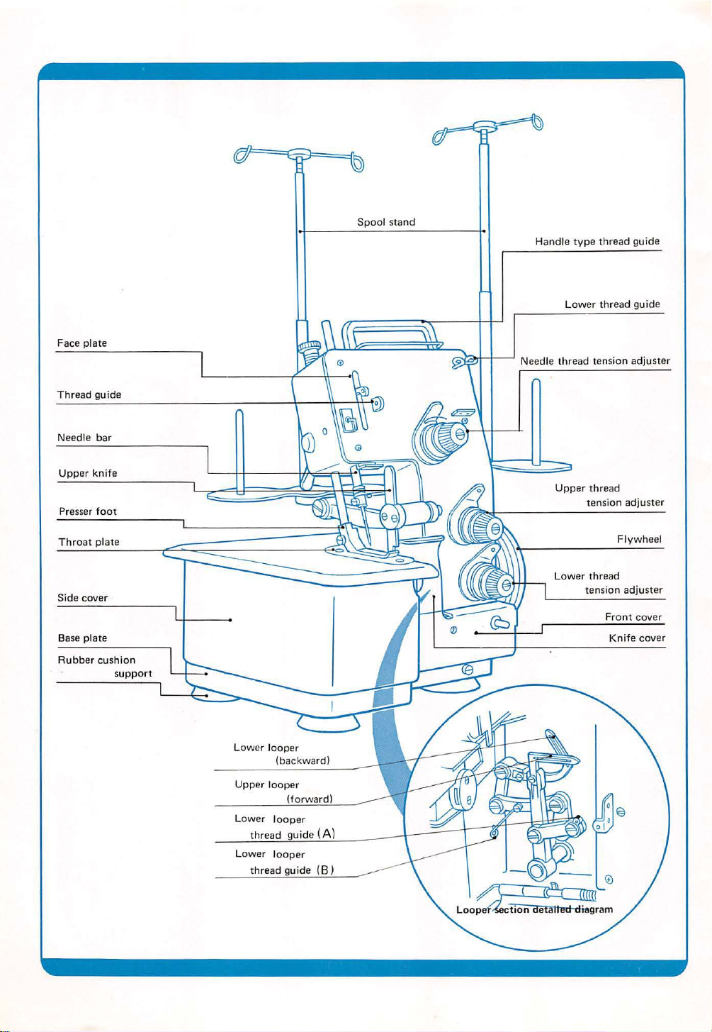
Spool
stand
Handle
typ
e thread guide
Face
plate
Thread guide
bar
Needle
Upper knife
Presser
foot
Throat plate
Si
de
cover
ate
Base pl
Rubber
cushion
thread gui
Lower
Needle thread t
ppo
rt
su
ension adjuster
Upper
thread
tension
Lower thread
tension a
Front
de
adjuster
Fl
ywhe
el
djuste
cover
Knife cover
r
Page 3
PREFACE
Than k you for your
Pl
ease refer
se
rvice in
1.
2. How
3.
4.
5. H
6. Adjusting sti
7.
8. L
9.
10
. Chec ki ng
11
. Changing the
12.
13
. Specifications ...
. Table showi ng relati o nship betw
14
to th
the future.
Setting
Correct installation of th e
1-1
1-
2 H
ow
ow
1-3 H
Con
1-4
to
2-1 H
ow
2-2 Sewing . . . . . . . .
Thread tension
Presser foot ad ju
ow
to
Replacing the c
ubr
ication
Set
ting
Supp
leme
purchase
is
booklet for
up the machine
to assemble
to set up the spool s
necti
ng
the con
thread correc tly
to thread correct ly ............
adjustment ......
stme
insta
ll
the needle
cth
length
utting
.....
......
up
the
sewing machine l
and
adjustment . . . .
carbon
nt
......
...
of
Baby L
ock
Model EF-
opt
imum use of this mach ine a
.................
motor ...
the spool stand .
tand
troller
to
...
. . ....
.......
nt . . . . . . . . . . . . . . . . . . . . . . . . . . . . . . . 8
..........
knives ...
brush es
.. ..
. .
. . . .
..............
......
amp
.... .......
of the
. .... . .
...................
...... . .
.......
the moto r
................
.......................
...
...........
. .
.........
.......
...
.....
. .
........
motor
.....
een thread
405
.
nd
.
.....
..
....
. ........
.
..........
.................
.
.................
. . . .
. ....
.....
.....
..
................ 14
and cloth
...... .
..........
. . .
.......
..............
. . . .
....
...... ..
...
.........
......
..
..........
.
......
. .
..
........
.
...
.....
......
. .
..
. .
for
. . . . 1
...
. . . 1
. . 2
...
.4
.4
...
. 9
1 0
..
11
11
..
12
13
...
15
16
long
1
3
6
7
8
Page 4
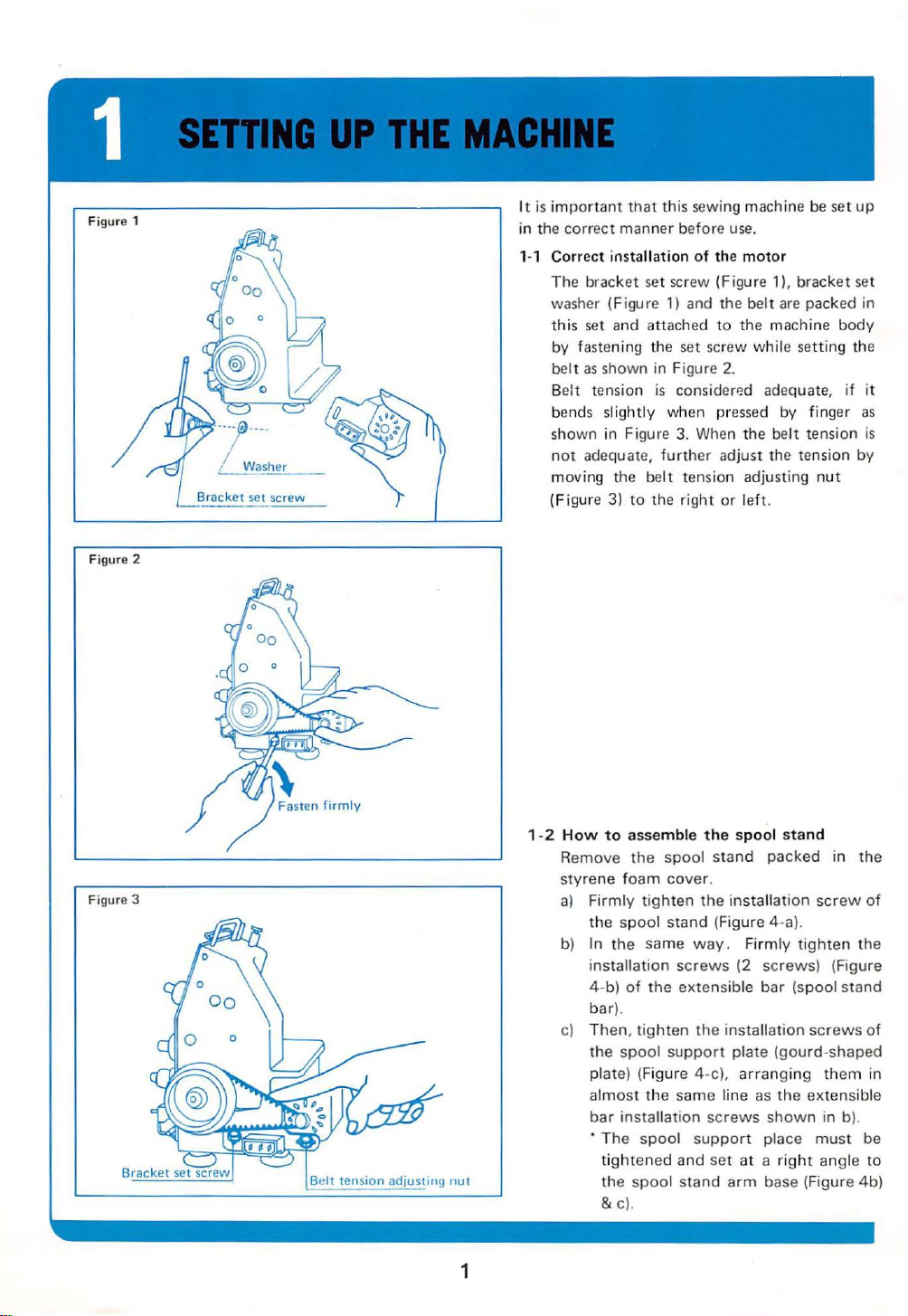
Figure 1
Figure 2
Bracket
set
screw
It is
impor
tant that this
in t
he
correc t manner before
1-1 Corre
ct
installation
T
he
bracket set screw (Figure 1
washer (Figure 1) and the
th
is
set and attached
by fastening t he set screw
belt
as
shown in Figure
Be
lt tension
be
nds slightly
sh
own
not
adequat
moving the
(Fi
gure 3) to th e
is
in Figure
e,
be
when pr
further
lt
sew
ing machine be set
use.
of
the
motor
),
brac
belt
are
packed in
to
the machi
wh
2.
considerP.d adequate,
essed
3.
When t
he
adjust the tension by
tension adjusting
right
or left.
ne
ile setti
by finger
belt tension
nut
up
ket
set
body
ng the
if it
as
is
1-2
How
to
assemble the
Figure 3
Remove
styre
a) Firmly
b)
c) Then.
the
ne foam
tighten the in
the
spool stand (Figure 4-a).
In
the
same
installation
4-b)
of
the extensible
bar) .
tighten
the
spool
plate) (Figure 4-c), arran
al
most
the same line
bar
insta
llation
· The
spool
ti
ghte
ned and
the
spoo
&
c)
.
1
spool
cover
way.
screws
the
support
screws
suppo
l stand
spool
stand
stand
.
set
packed in
stallation screw
Fir
mly
tighten
(2
screws)
bar
(spool stand
installation scr
plate (gourd-shaped
ging
them in
as
th e extensib le
shown
rt place
at a r
arm
base (Figure
ight
in b
must
angle to
the
of
the
(Figure
ews
of
).
be
4b)
Page 5
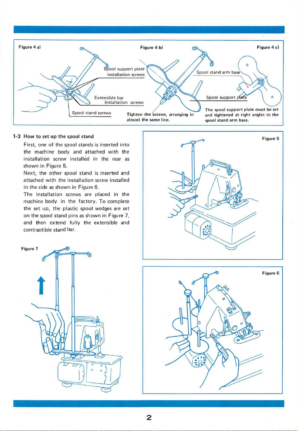
Figur
e 4 a)
Figur
e 4 b)
Figur
e 4 c)
1·3
How
to
set
up
First,
one
of
the
mach ine
installation screw inst
shown in Figure 5.
Next,
the
other spool
attached
in
Th
machine
the
on
and
the
side as
e install
set
up,
the
spoo
then
with
ation
body
l st a
extend
contractible
Figur
e 7
E
xtens
the
spool s
tand
the spool s
body
the
show
tands
is
and
attached
all
ed
in
stand
is inserted
installation screw installed
n in Figure 6.
screws are placed in the
in
the
the
nd
stand
plastic
pins as
fully
bar.
factory.
spool
To
wedges are set
sho
wn
the extensible
ible
bar
installation
inserted
with
into
the
the rear as
and
complete
in Figure 7,
and
screws
Tight
en the screw
alm
ost
the same line.
s,
arranging
in
Spool support
The
spool support
nd
tightened
a
spool
stand
plate must
at
right ang les
arm base.
be set
to
Figur
the
e 5
t
2
Page 6
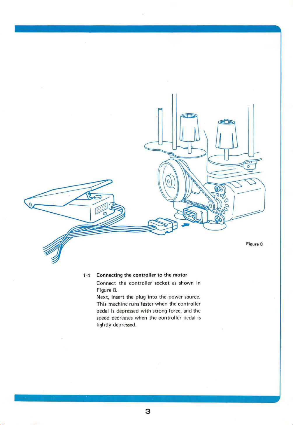
1-4 Connecting
Connect the
Figure 8.
Next, i
This machine run s faster
pedal is depressed wi
speed decreases when
lightly depressed.
nsert
the
controller
controller
the plug
to
the
motor
socket as shown in
into
the
power sour
when
the
controller
th stro
ng force, and
the
controller pedal is
ce.
the
3
Page 7

2-1 H
ow
( 1)
Spoo
Ch
ra
is
(Figure
r
such a way
is
(2) H
T
ord
After
front
while
thread
em
* T
need
to
thread
l se
tti
eese
spool thr
lly
used
possible
9) as
equ
ired
that
on
the
bottom
ow
to
thread nee
he
thread
er shown in F
inserting
to
faci ng
should
.
weezers are
le
eye.
correctly
ng
for
this
to use
we
the
that the
should
rear
through
the
machine,
be
ead
(F igure 9) is
machine, how
bobbin
ll. In
this
bobbin
.
igure
the
helpful for
spool be set in
winding stop
d le
thread
be inser
11
.
thr
ead
the
the end
pulled
out
spool
case,
correc
ted
from
needle
about
threading
gene
eve
r,
thread
it
groov
in the
the
eye
of
the
tly
10
Cheese
spool thread.
-
it
is
e
Boddin
spool thr
~
ead.
w;o
Figure 9
d;og><
op
~
Figure
10
Tension
discs
P
ass
thread be
Correct
twe
en t
wo
ten
threading at needle b
sion disc
ar
section.
4
s.
Fig
ure
12
Page 8

Figur
e 13
(3)
Upper
First,
re
Figu
Th
en, the
order
After
cover.
and
lower
open the
13.
threads shou
as s
hown
inserting
threads
front
ld be inser
in Figure
the
thread,
insertion
cover as sho
ted
15 and
close
Figure 16.
the
wn
in the
fro
nt
in
5
Page 9

2·2
Sewing
(1)
After
the
the
ends
fingers
of
tension
the
as shown
flywheel wi
clockwise direction.
(2)
threads
cloth, a
If
threads
that
that
Refer
ment".
are intertwining.
nd
the
tension
is
creases w
the
to
(Page 7)
completion
of
three
the left
hand
in
th
the
begin
to
sew.
balance
not
satisfactory,
ill
appear
seams will
the
"Thread
of
threading, hold
threads with
creat
ing a
Figure 18
right
and
hand
Confirm that
Then,
(Fiture
on
become
of
it
the
18)
the
is
cloth
irregular.
tension
the
minor
turn
in
the
three
set
the
three
possible
or
adjust
Figure 19
·
(3)
After
about
for
retaining
Figure
sewing is
2-3
em
and
20.
completed,
at
the
end
cut
the
blank stitch
of
the c
re
as s
hown
loth
in
Detail
ed
intertwining
thread.
diagram
showi
condition
ng
the
of the
Figu
re
20
6
Page 10

(A) When the t
Figure
22
(B) Wh
en
Fi
gure 23
(C)
When the tens
ension
the tensi
of the uppe
on
of the l
ion
of the
r thread is t
ower thr
need
le thread is
ead is
oo stro
too stron
loo
se.
ng.
g.
3-
1 H
Thread
cording
thread
the
adjust
21) Thr
turning
ow
to adju
need
st
tension
to
the
being used.
le,
upper
ers
while
ead tension
in a
clockwise
t he over
adjustment
type
of
Adjust
and
watching
may
edg
ing seams
clo
th,
the
lower
the
be
strenghtened
direction
will
diff
er
ac·
thickness,
and
tension using
thread ten
sion
seams. (Figure
by
.
Figure 24
(D
) Ideal stitching
ure 25
Fig
Needle
Upper
sea
m.
thr
thread
ead
Lower thread
1. Wh
2.
3.
4. When the
7
en
strong
tension
When
strong
tension
When
l
oose (Fi
tension
Fi
gure
the
tension
(Figure
adjuster.
the
tension
(Figure
adjust er.
the
te nsion
gure 24),
adjuster.
stict
h ing seams
25,
the tensions are
of
the
upper
22),
loosen
the
of the
lower
23), loosen
of
the
the
need
tighten the needle
appear
satisfactory.
Up
per thread
tension
Needle
tension
thread
upper
thread
lower
le th
as
adjuste
thread
adjuster
is
thread
is
th read
read
thread
shown
r
too
too
is
in
Page 11

The
preser
foot
is adj
usted
for
Adjust
very thi
Sew thin
thick
*
only
ck
cloth
cloth
clo
th with a stronger
Tighten
cloth. Loosen
W
ith
machine, "ORG
No. 11
(1 )
For
fly-w heel
far
Next,
(2 )
27).
need
first,
ely
clamp.
(3) Firmly
F
it
such a way
groove
machine
regard
can
needle
as
it
loosen
insert
le
and
deep into
or
the
is
requested
presser
be
will go.
drop
tighten
is
adjustment
standard
in
the
case
is
being
with a weaker pressure,
adjusting
the
to
the nee
AN" BLx1
used
for
installation,
so
as
to
the
the
hole
secondly
the
the
di r
ection
so
facing
as
shown
of
(medium)
when very thin
sewn
.
pressure
screw
screw
for
dles
(orDBx1)
overedging.
raise
the
need
le c l
amp
tip
of
the
(Figure
that
the
27)
insert
the
needle
hole
needle clamp
of
inserting
the
that
the
front
in
Figure
this
for
first
nee
needle
needle
when
machine
thickness
.
for
thick
thin
cloth.
this
No. 14
turn
dle
screw
on
the presser
needle
of
the need
screw.
the
be
thread
facing the
28.
.
or
and,
sew
bar
up
(Figure
into
complet-
need
set
guide
How to adju
st
the pressure.
Presser a
Ll"
18
.5
mm
Very
l.~
ing
and
Needle
Need
clamp
le
the
as
the
le
le,
in
-------
V
screw
clamp
screw
thick
t
~
ery thin
Weak
Strong
djusting
screw
cloth
cloth
Med i
um thi
Needle
ck
cloth
Figure 26
Figu
drop hole
re
27
Thr
ead guide
Needle eye
8
ndent
I
Figure
28
Page 12

- -
6 . . .
( 1)
Holding
hand, grasp the heart-shaped driver
the accessories box
and
screw. The feed regul
can
in a counterclockwide
pressing the
shaped driver.
(2)
Set the graduation on the feed regulator
knob
numbe r on the feed
larger the
(3)
After
tight
the flywheel
loosen the feed re
be
loosened by turning the
fixing
to
the indicator. The larger the
sea
ms
will
completing adjustments, firmly
en
the feed regulator
with
the right
with
the
left
gulator
ator
fixing
flywhe
direction
screw w
ith
the heart·
regulator knob, the
be.
fixing screw.
in
hand
fixing
screw
el
while
Figure
29
Heart-shaped
Figure
30
I
u
\
driv
er
Feed
regulator
fixing screw
9
Page 13

The
knife
should
the
electric
1) The upper
loosening the
knife may
k
nife ho
screw
power
upp
be
lder set screw and the l
as
shown in Figure 31.
ower
L
be
changed
source.
knife
er
knife
changed after loosening the
only
after
removing
may be changed after
set screw and the
ower
knife set
l Figure 31
-:6"'
Lower
knife
knife set screw
holder
Upp
set
er knife
set sc
screw
lower
lower
rew
2) Th e position
of
the lower
arranged in such a way
in the indentation
plate
as
shown in Figure
3)
Th
e normal position
knif
upper
upper
e can
knife
ing operation.
ting
edge
of
about 0.5"'1.0mm
tip
of
the
cutting
for
be
reaches its lowest
The
the
upper
against the surface
edge
(Figure 32)
Figure showing
highest
position
upp
.
er
knife
' .
Figure showing
position.
upp
er
knife
knife
must
be
so
that
it
can
be
set
the
knife
in the
throat
32
for
fixing
the
determined when the
point
dur-
front
tip
of
the cut-
knife
will
drop
of
the
on
the lower knife.
at
its
Thro
at
plate
-------
' I
----.._, I
at
i s lowest
Figure
32
10
Page 14

Figure
Five/ten
one
only
33
oiling
in
this
drops of
oil for
are necessay
portion
.
As special materials (oil
for
parts
of
used
lubrication
is
provided
provided no
to
those parts marked in r
from the outside
tho
se
parts shown
is suffici
ent
this m
is
negligible. However, since oil wi
for
the inner
more th
an once
of
the machi
in Figu
for
one oiling.
imp
regnated metal) are
achine
actual additional
sec
tions, oil sh
or
twice per m
ed
which can
ne,
in addition
re
33
1-2 drops
ould
ont
be
of
ck
be
h
seen
to
oil
Wh
en using a working lam
to u
se a co
position
mercially
as
shown in Figur e 34.
p,
it
is recommend
ava
ilable lamp set in the
Figu
re
ed
34
1 1
Page 15

This machine
no need
tely
ments.
Th
e following five
instances where difficulties are likely
through lack
Th
ese
when operating this machine.
A)
When
Is
the
plug
Is
the
Is
the
B)
When
Have
Is
the
Is
the
Is
Are there a
type
Has
C)
When
Is
plate or presser
Has
D)
When
Is the needle
Has
Is
E)
When
Is
wer
lo
Have
is
so designed
for
complex
examples
of
fundamental
points
there
the
the
the
the
should
the
machine does
electric
receptab
any
motor?
belt
loose?
the
thread
the
threads
thread
needle bent?
presser pressure
ny
of
thread
the
needle been inserted
the
needle breaks -
needle
the
needle been inserted
the
seams are
the
needle been inserted
presser pressure sufficient?
the
seams are
tension
and
needle
the
threads
be
carefully considered
cord
properly inserted into
le?
slipping in
breaks-
been inserted correctly?
tension
bent
too
adequate?
problems
being used?
touching
foot?
irregular-
or
the point
not
adjustment
threads
been correctly inserted?
that
there
professional adjust-
are the only possible
adjustments.
not
operate-
the
set
strong?
with
regard
correctly?
against
correctly?
worn?
correct
satisfactory-
of
satisfactory?
is
to
posit
the
ly?
the
absolu-
occur
the
ion
of
to
the
throat
upper,
12
Page 16

Two
carbon brushes (in
to
attached
be used
for
the
machine. The carbon brushes
to
the
according
worn
away
A) Pe
riod
The ca
they
have
following
after
I ong hours
for
changing carbon brushes
rbon brushes shou
worn
too
short
carbon brush figure).
B)
First
caps
remove the
(see
figure of
motor.
motor),
brushes.
Fig
ure
of
carbo
n brush
10mm
I
1--
L
-R
\.\\~
two
positions) are
motor
on
this sewing
should be changed
method,
of
ld
as
use.
be
changed when
for
contact (see
they
Remove the brush
and replac e the
Brush cap
are
(two)
•
The
carbon
brushes
should
th
e brush
sec
tion
mately 3 mm
Carbon brushes
sewing mac
shop.
Not
e: Specia l care should be taken
as shown
hin
e shop
has worn
may
regard to the aforemen
fa
ilure to
sparks
consequently
change the brush
emitting
from
further damage the
be
down
in
the
be
purchased fr
or
electr
tion
es
the
motor
figure.
Bracket set scr
changed
to
ical ap
ed
points
may
which
motor.
when
approx
om
plian
resu
any
ce
wit
lt in
will
ew
i·
h
as
13
Page 17

Detailed list
I.
Machine
2.
Motor
3.
Controller
of
content
4 Spool st and ( 2 sets)
5.
Vi
nyl cover
ts)
driv
(f
"ORGAN"
er
knife
be
booklet
er
ps
or
motor
driver
used for
using the machine
6. Instruction
7. Accessory box
(Conten
Sc
rew
Pl
us driver (Ph il li
Spanner
Needles
Upp
Tweezers
Cleaning brush
Oil
receptacle (capaci
Heart·shaped
(for adjusting sti tch length)
It
is
recommended
side cover
at
the
time of
Figu
re
36.
s
screw driver)
bracket)
BLx 1
(orDBx
No. 14 .
ty
: 30cc)
that the pocket on the
sec
uri ng the accessories
1)
No
.11 10
as
shown in
1
14
Page 18

ITEM
SPECIFICATION
Overedging width
Stitch length (feed)
Needle bar stroke
Knife
movement
Presser I ift
(upward volume)
Feed
dog height 0.8 m/m (standard)
Needle
Number
Method
Machine dimensions
Weight
of
threads 3
of
lubrication
of
machine 9.8 kg
4m
/m
1-6
m/m
27 m/ m
8m
/m
6m/m
"ORGAN"
Semi·automatic
Length
x Height
(with
Blx
1 (orDBx
oil
250 m/m x Breadth 250 m/m
280 m/m
motor)
1) No. 14, No.11
wick
lubrica
tion
15
Page 19

No. Type
of
cloth
U
se
Type
of
thread
Length of stitch
Ordinary
1
(cotton,
satin,
Thick
2
(tweed, overcoat
denim,
Knitted
(knitted
3
knitted
cloth
tricot
, linen, Overedgi
cloth
in general)
cloth
thick
cloth
suit cloth')
Overedging
cloth
goods, Overedging
cloth)
ng
Cotton
Silk #
50-
#60
- #1 00
#100
Cotton #40 -#60
Silk#40-
Tetron and
nylon
#6
threads
0
woo
Wooly nylon and
tetron
threads
3.0m/m-
3.0m/m-
lly
3.0m/m-5.0m/m
4.0m/m
5.0m/m
16
1972
P
rint
· 7 · I
ed
in Japan
Page 20

 Loading...