

JUKI AMS-251/IP-420 Instruction Manual

AMS-251 / IP-420
INSTRUCTION MANUAL
* "CompactFlash(TM)" is the registered trademark of SanDisk Corporation, U.S.A.

CONTENTS
I. MECHANICAL SECTION (WITH REGARD TO THE SEWING MACHINE) 1
1. SPECIFICATIONS ....................................................................................................... 1
2. CONFIGURATION ....................................................................................................... 2
3. INSTALLATION ........................................................................................................... 3
3-1. Removing the machine head xing plate ....................................................................................3
3-2. Setting up the machine..................................................................................................................4
3-3. Preparations of switches...............................................................................................................6
3-4. Connecting the power switch ....................................................................................................... 7
3-5. Installing the panel.........................................................................................................................8
3-6. Installing the thread stand ............................................................................................................8
3-7. How to install the thread stand for bobbin winding ...................................................................9
3-8. Connecting the cord .................................................................................................................... 10
3-9. Installing the air hose .................................................................................................................. 13
3-10. Cautions for the compressed air supply (source of supply air) facility ...............................14
4. PREPARATION OF THE SEWING MACHINE .......................................................... 15
4-1. Lubrication....................................................................................................................................15
4-2. Adjusting the oil quantity in the hook ........................................................................................ 16
(1) Checking the oil quantity in the hook .......................................................................................... 16
(2) Adjusting the hook oil quantity (oil spots) ....................................................................................17
(3) Sample of proper quantity of hook oil (oil spots) .........................................................................17
4-3. Checking the emergency stop switch ........................................................................................ 18
4-4. Attaching the needle ....................................................................................................................18
4-5. Needle size and gauge.................................................................................................................19
(1) Adjustment .................................................................................................................................. 19
(2) Gauge ......................................................................................................................................... 19
4-6. Threading the machine head ......................................................................................................20
4-7. Installing and removing the bobbin case ..................................................................................21
4-8. Installing the bobbin .................................................................................................................... 21
4-9. Preparing the cassette clamp ..................................................................................................... 22
4-10. Adjusting the thread tension ....................................................................................................25
4-11. Intermediate presser height ......................................................................................................26
4-12. Adjusting the thread take-up spring ........................................................................................26
5. OPERATION OF THE SEWING MACHINE ............................................................... 27
5-1. Sewing...........................................................................................................................................27
II. OPERATION SECTION (WITH REGARD TO THE PANEL) .................... 28
1. PREFACE .................................................................................................................. 28
2. WHEN USING IP-420 ................................................................................................ 32
2-1. Name of each section of IP-420 .................................................................................................. 32
2-2. Buttons to be used in common ..................................................................................................33
2-3. Basic operation of IP-420 ............................................................................................................ 34
2-4. LCD display section at the time of sewing shape selection .................................................... 35
(1) Sewing shape data input screen .................................................................................................35
(2) Sewing screen ............................................................................................................................37
2-5. Performing sewing shape selection ........................................................................................... 39
2-6. Changing item data ...................................................................................................................... 41
i

2-7. Checking pattern shape ..............................................................................................................43
2-8. Performing modication of needle entry point ......................................................................... 44
(1) Editing the thread tension ........................................................................................................... 44
(2) Editing the intermediate presser height ......................................................................................45
2-9. How to use temporary stop ......................................................................................................... 46
(1) To continue performing sewing from some point in sewing ........................................................46
(2) To perform re-sewing from the start ............................................................................................ 47
2-10. When setting of sewing product is difcult because of interruption of needle tip .............48
2-11. Winding bobbin thread .............................................................................................................. 49
2-12. Using counter ............................................................................................................................. 51
(1) Setting procedure of the counter ................................................................................................51
(2) Count-up releasing procedure ....................................................................................................53
(3) How to change the counter value during sewing ........................................................................ 53
2-13. Performing new register of users’ pattern ...............................................................................54
2-14. Naming users’ pattern ...............................................................................................................55
2-15. Performing new register of pattern button .............................................................................. 56
2-16. LCD display section at the time of pattern button selection .................................................57
(1) Pattern button data input screen .................................................................................................57
(2) Sewing screen ............................................................................................................................59
2-17. Performing pattern button No. selection ................................................................................. 61
(1) Selection from the data input screen ..........................................................................................61
(2) Selection by means of the shortcut button ..................................................................................62
2-18. Changing contents of pattern button ....................................................................................... 63
2-19. Copying pattern button .............................................................................................................64
2-20. Changing sewing mode ............................................................................................................. 65
2-21. LCD display section at the time of combination sewing ........................................................ 66
(1) Pattern input screen ....................................................................................................................66
(2) Sewing screen ............................................................................................................................68
2-22. Performing combination sewing ..............................................................................................70
(1) Selection of combination data .....................................................................................................70
(2) Creating procedure of the combination data ...............................................................................71
(3) Deleting procedure of the combination data ............................................................................... 72
(4) Deleting procedure of the step of the combination data .............................................................72
(5) Setting of the skip of steps ..........................................................................................................73
2-23. Using the simple operation mode ............................................................................................73
2-24. LCD display when the simple operation is selected...............................................................74
(1) Data input screen (individual sewing) ......................................................................................... 74
(2) Sewing screen (individual sewing) ..............................................................................................77
(3) Data input screen (combination sewing) .....................................................................................80
(4) Sewing screen (combination sewing) .........................................................................................82
2-25. Changing memory switch data ................................................................................................. 84
2-26. Using information ......................................................................................................................85
(1) Observing the maintenance and inspection information ............................................................. 85
(2) Releasing procedure of the warning ........................................................................................... 86
2-27. Using communication function ................................................................................................87
(1) Handling possible data ...............................................................................................................87
(2) Performing communication by using the media .......................................................................... 87
(3) Performing communication by using USB ..................................................................................87
(4) Take-in of the data ......................................................................................................................88
(5) Taking in plural data together ...................................................................................................... 89
ii

2-28. Performing formatting of the media ......................................................................................... 91
2-29. Operation at the time of X/Y motor position slip .....................................................................92
(1) When the error is displayed during sewing ................................................................................. 92
(2) When the error is displayed after end of sewing .........................................................................93
(3) When the rest switch is not displayed .........................................................................................93
3. MEMORY SWITCH DATA LIST ................................................................................. 94
3-1. Data list ......................................................................................................................................... 94
3-2. Initial value list .............................................................................................................................99
4. ERROR CODE LIST ................................................................................................ 101
5. MESSAGE LIST ...................................................................................................... 112
III. MAINTENANCE OF SAWING MACHINE ...............................................115
1. MAINTENANCE ....................................................................................................... 115
1-1. Adjusting the height of the needle bar (Changing the length of the needle) ....................... 11 5
1-2. Adjusting the needle-to-shuttle relation .................................................................................. 116
1-3. Adjusting the vertical stroke of the intermediate presser ...................................................... 11 8
1-4. The moving knife and counter knife......................................................................................... 118
1-5. Thread breakage detector plate ............................................................................................... 119
1-6. Amount of oil supplied to the hook .......................................................................................... 119
1-7. Periodical cleaning of the oil shield ......................................................................................... 119
1-8. Replacing the fuse ..................................................................................................................... 120
1-9. Replenishing the designated places with grease ................................................................... 121
(1) Types of grease ........................................................................................................................ 122
(2) Points to be applied with JUKI Grease A ..................................................................................122
1-10. Troubles and corrective measures (Sewing conditions)...................................................... 124
2. OPTIONAL ............................................................................................................... 126
2-1. List of the needle hole guides and intermediate pressers ..................................................... 126
2-2. Bar code reader .......................................................................................................................... 127
iii

I. MECHANICAL SECTION (WITH REGARD TO THE SEWING MACHINE)
1. SPECIFICATIONS
1 Sewing area X (lateral) direction Y (longitudinal) direction
1,000 mm × 600 mm
2 Max. sewing speed 2,500 sti/min (When sewing pitch is 3 mm or less)
3 Stitch length 0.1 to 12.7 mm (Min. resolution : 0.05 mm)
4
Feed motion of feeding frame
5 Needle bar stroke 41.2 mm
6 Needle GROZ-BECKERT 135x17, ORGAN needle DPx17
7 Amount of lift of the ma-
chine head unit goes up
8 Intermediate presser stroke 4 mm (Standard) (0 to 10 mm)
9 Lift of intermediate presser 20 mm
10 Intermediate presser DOWN
position variable
11 Shuttle Full-rotary three-fold capacity hook
12 Lubricating oil New Defrix Oil No. 2 (Supplied by oiler)
13 Memory of pattern data Main body, Media
14 Temporary stop facility Used to stop machine operation during a stitching cycle.
15 Enlarging / Reducing facility Allows a pattern to be enlarged or reduced on the X axis and Y axis independently
16 Enlarging / Reducing
method
17
Max. sewing speed limitation
18 Pattern selection facility Pattern No. selection method
19 Bobbin thread counter UP/DOWN method (0 to 9,999)
20 Sewing counter UP/DOWN method (0 to 9,999)
21 Memory back-up In case of a power interruption, the pattern being used will automatically be stored
22 2nd origin setting facility Using jog keys, a 2nd origin (needle position after a sewing cycle) can be set in the
23 Sewing machine motor Servo-motor
24 Dimensions 2,400 mm (W) × 1,800 mm (L) × 1,600 mm (H)
25 Mass (gross mass) 947 kg
26 Power consumption 800 VA
27
Operating temperature range
28 Operating humidity range 35 % to 85 % (No dew condensation)
29 Line voltage Rated voltage ±10% 50 / 60 Hz
30 Air pressure used Standard 0.35 to 0.5 MPa (Max. 0.55 MPa)
31 Air consumption 1.8 dm3 / min (ANR)
32 Needle highest position stop
facility
33 Noise - Equivalent continuous emission sound pressure level (LpA) at the workstation :
1
*
"sti/min" is an abbreviation for "stitches per minute."
Intermittent feed (2-shaft drive by stepping motor)
50 mm
Standard 0 to 3.5 mm (Max. 0 to 7.0 mm)
• Main body : Max. 999 patterns (Max. 50,000 stitches/pattern)
• Media : Max. 999 patterns (Max. 50,000 stitches/pattern)
when sewing a pattern. Scale : 1% to 400% times (0.1% steps)
Pattern enlargement / reduction can be done by increasing / decreasing either stitch
length or the number of stitches. (Increasing/decreasing stitch length only can be
performed when pattern button is selected.)
200 to 2,500 sti/min (Scale : 100 sti/min steps)
(Main body : 1 to 999, Media : 1 to 999)
in memory.
desired position within the sewing area. The set 2nd origin is also stored in memory.
5˚C to 35˚C
After the completion of sewing, the needle can be brought up to its highest position.
A-weighted value of 78.2 dB; (Includes KpA = 2.5 dB); according to ISO 10821C.6.2 -ISO 11204 GR2 at 2,500 sti/min *1.
– 1 –
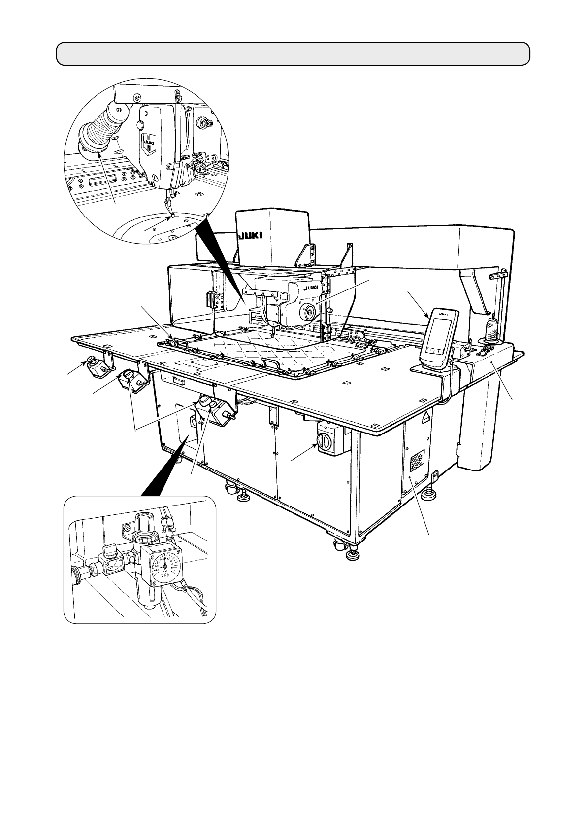
2. CONFIGURATION
❹
❸
❼
❾
❶
❺
❷
❽
❻
Air regulator
Machine head
❶
Cassette clamp
❷
Intermediate presser
❸
Thread stand
❹
Operation panel (IP-420)
❺
Power switch
❻
Emergency stop switch
❼
Start switch (green)
❽
Pause switch (white)
❾
Eject switch (blue)
Control box
Bobbin winder
– 2 –
3. INSTALLATION
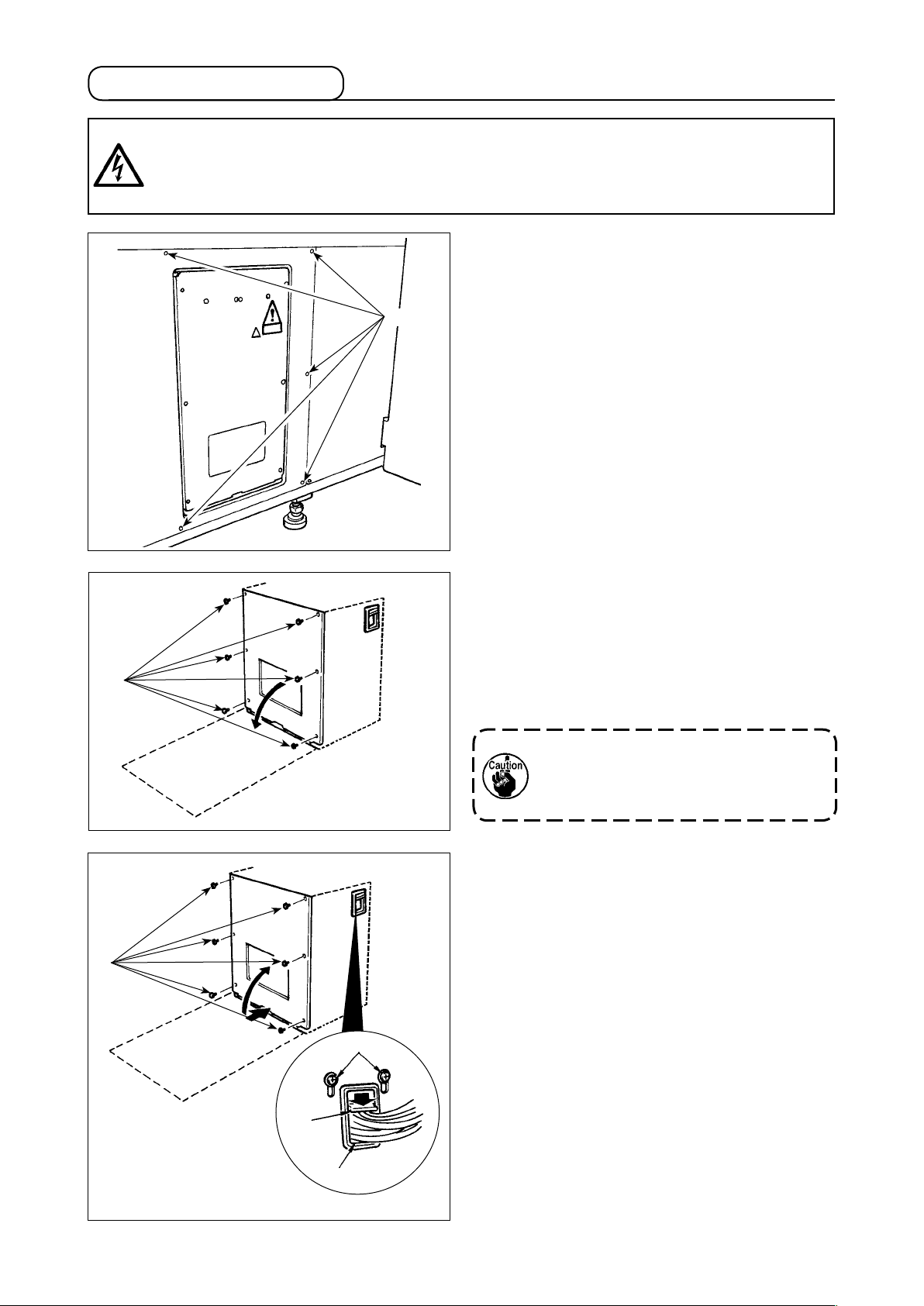
3-1. Removing the machine head xing plate
1) Open machine head safety cover ❶.
❶
2) Remove two setscrews ❷. Detach machine
3) Re-tighten two setscrews ❷ which you have
❷
Keep the machine head safety cover
closed while the sewing machine is
❶
in operation.
head xing plate ❸.
removed in step 2) back in their tapped holes.
❸
– 3 –
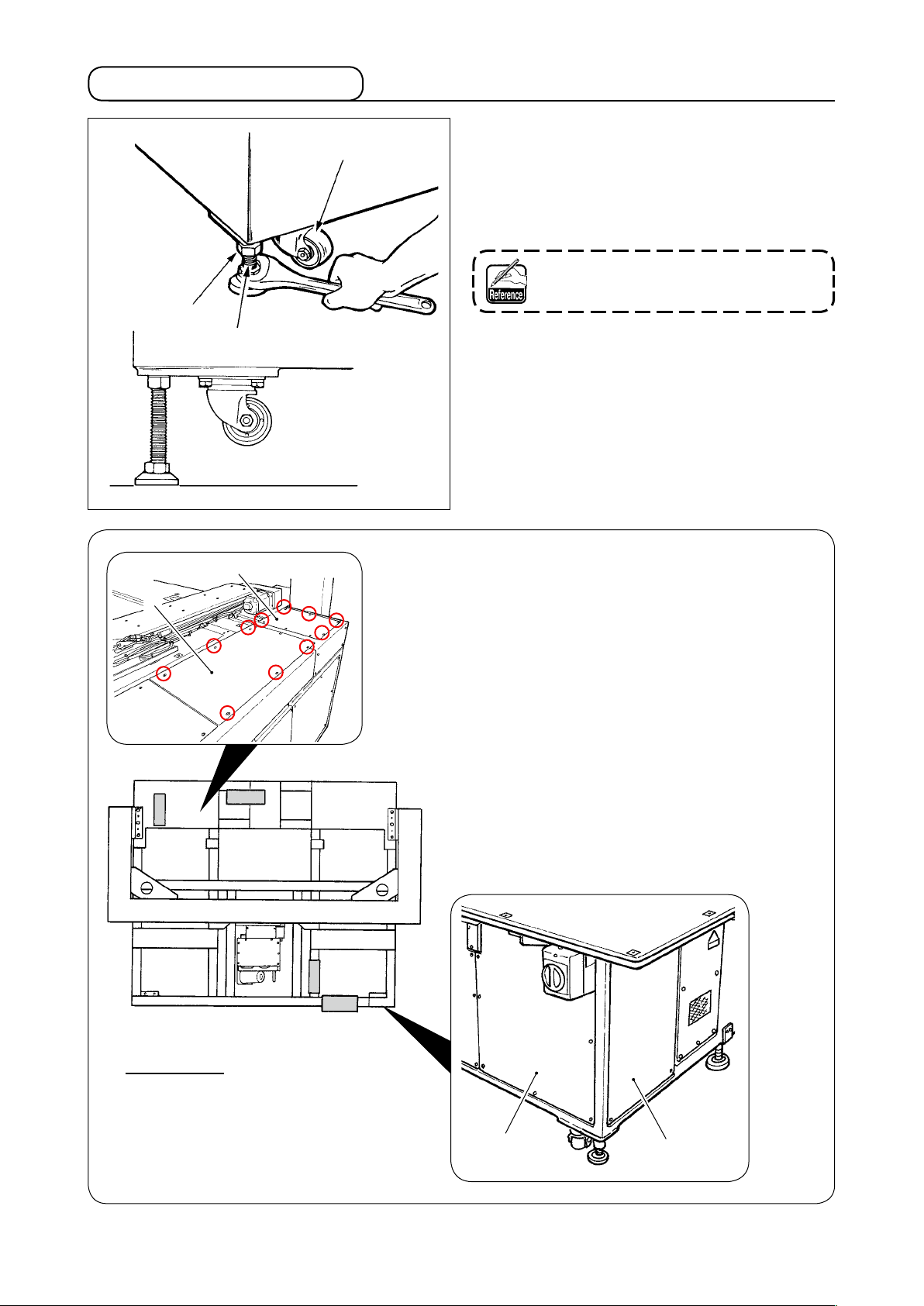
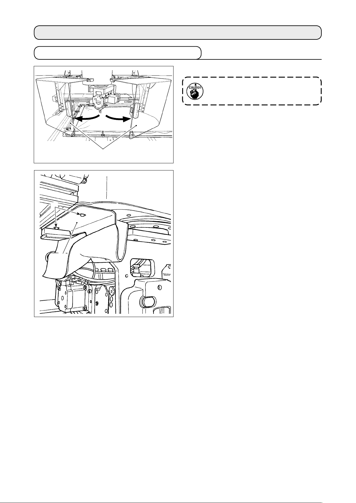
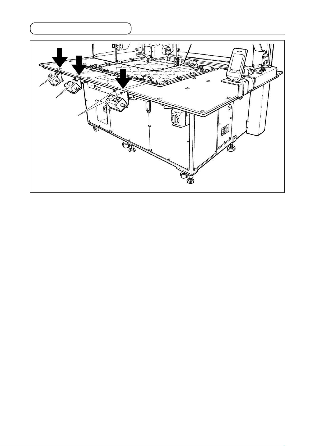
3-2. Setting up the machine
❶
❷
❸
1) Install the machine on a at place with leveled.
2) Loosen nut ❶ and turn level adjuster ❷ to lift
the machine until caster ❸ idles.
3) After the machine has been set up properly,
tighten nut ❶ and x level adjuster ❷.
Use 0.3-mm/m levels for leveling the
main body of device.
❺
A
❹
A
[Positions to check with levels]
1) Detach covers ❹, ❺, ❻ and ❼ of the main
body of device at four locations by removing
their screws.
2) Place a level respectively at positions A indicat-
ed in the gure. Adjust the adjusters mounted at
four corners so that the number of lines indicat-
ed on the level scale plate is within two.
After checking the levelness, adjust the adjuster
located at the center section of each strut until
it is stretched. Then, give it a 1/8 turn to further
stretch it. In this state, x each adjuster.
3) After the adjustment, re-place the covers back
in place.
A
Overhead view
Worker side
– 4 –
❼
❻
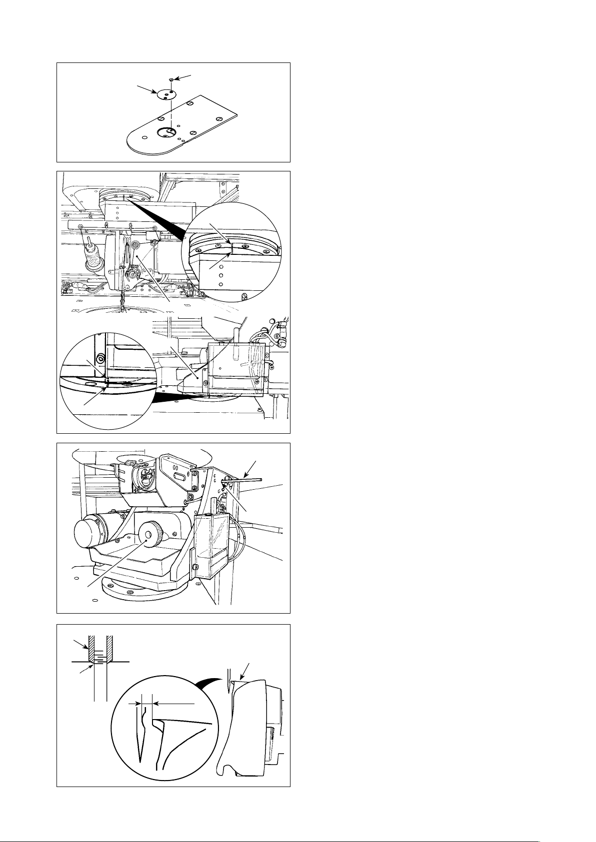
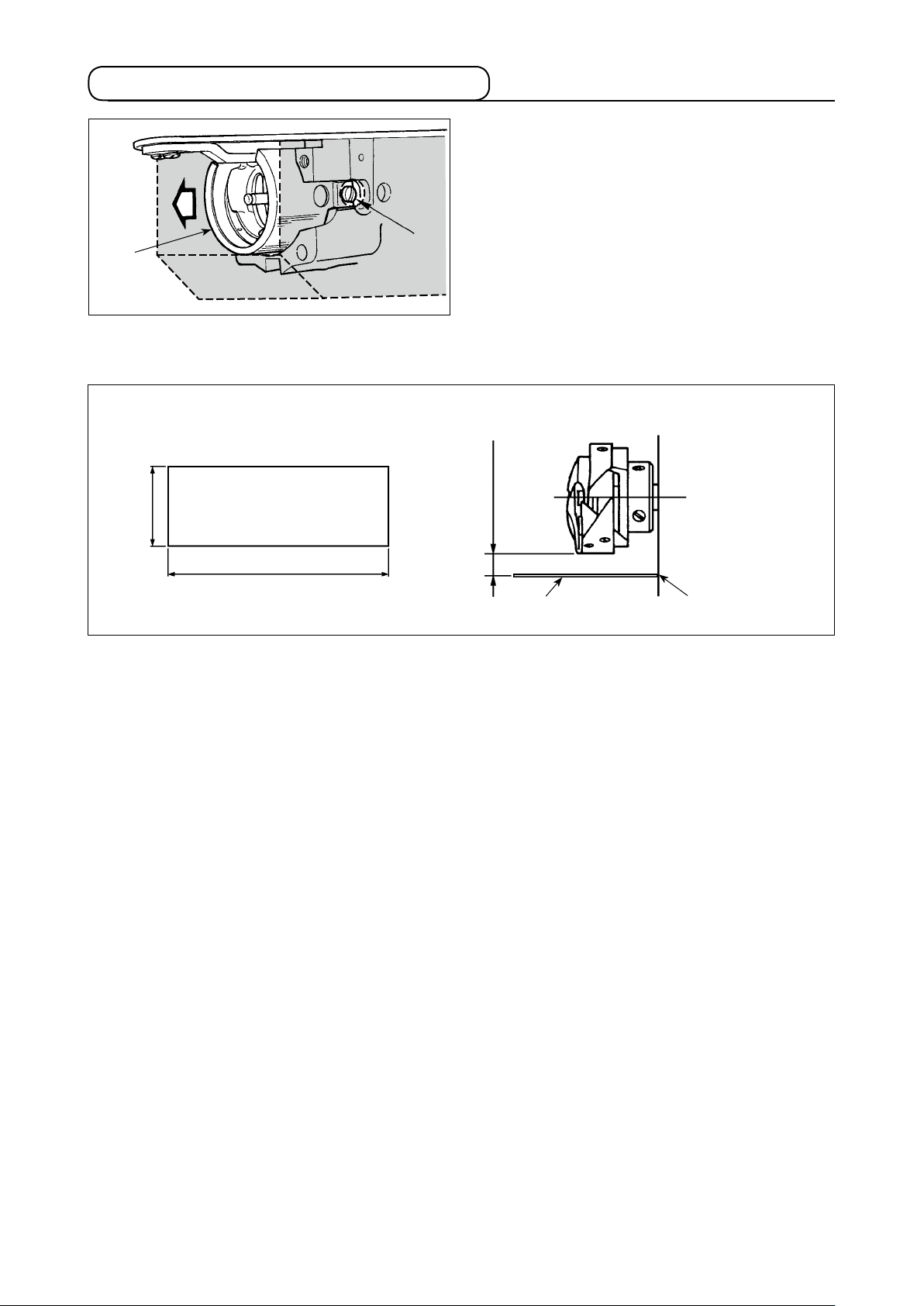
[Checking the needle entry]
B
❷
❹
❸
❶
A
B
1) Remove screw ❶. Detach needle hole guide
.
❷
2) Turn machine head ❸ and hook section ❹ so
that they face the front.
Align marker line A on the bearing with marker
line B on gear ring.
❾
❽
A
❼
0.03 to
0.1mm
❺
❻
3) Inserting hook shaft xing rod ❻ into hook
shaft xing rod insertion hole ❺, turn pulley
until hook shaft xing rod ❻ is fully inserted
❼
into the hole. (As a guide, turn the pulley until
the hook blade point is brought to the position
at which it faces upward.)
4) Turn the hand pulley of machine head until
needle-bar marker line ❽ is aligned with the
lower end of needle bar bushing ❾.
5) Check to make sure that a clearance of 0.03
to 0.1 mm is provided between the needle and
the hook blade point when the hook blade
point is aligned with the center of needle.
For each of four directions, check steps 2) to 4)
by turning the machine head and hook section
in steps of 90 degrees.
If the clearance of 0.03 to 0.1 mm is not pro-
vided between the needle and the hook blade
point, re-adjust the levelness of the main body
of device.
– 5 –
3-3. Preparations of switches
❶
❶
❶
Loosen respective screws ❶ of the power switch, start switch and emergency stop switch which are
placed upside down. Then, place the switches so that they face the worker side and re-tighten the
screws.
– 6 –
3-4. Connecting the power switch
Connecting the power source cord
The factory default voltage type is indicated on the voltage indication plate. Connect the cord in accor-
dance with the specications.
Voltage
caution seal
• Connecting single phase
200V, 220V, 230V and 240V
AC200 V, AC220 V
AC230 V, AC240 V
Brown OR
Green/Yellow
Black-No.1
– GND
Electric shock
warning label
Light blue OR
BLACK-No.2
Power source cord
Never use under the wrong voltage
and phase.
• Connecting three phase
200V, 220V and 240V
AC200 V, AC220 V, AC240 V
Green/Yellow
– GND
Black
Red White
Brown OR
Black-No.1
Green/
Yellow
Table
Brown
OR
Black-No.1
Control box
Plug
Light blue OR
BLACK-No.2
Power switch
Green/
Yellow
Light blue OR
BLACK-No.2
– 7 –
Red
Green
Red
Table
Black
Black
White
Power switch
Green/
Yellow
White
PlugControl box
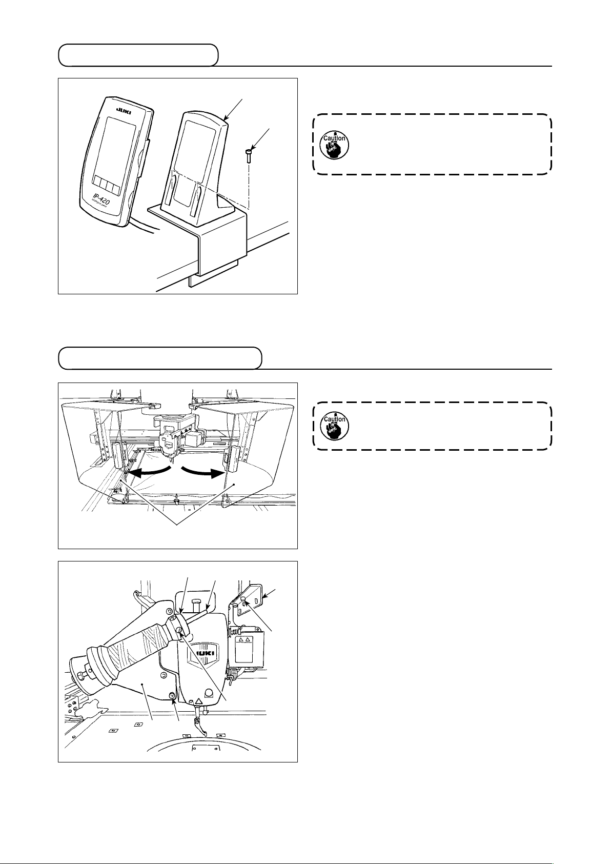
3-5. Installing the panel
❶
1) Fix operation box mounting plate ❶ with two
wood screws ❷.
3-6. Installing the thread stand
❷
Install the panel at the position where
X-move cover or head grip does not
interfere with it since breakage of the
panel will be caused.
1) Open machine head safety cover ❶.
Keep the machine head safety cover
closed while the sewing machine is
❶
in operation.
❹
❶
❺
❻
❽
❼
❸
❷
2) Fix thread guide plate ❷ with setscrews ❸ (two
small screws).
3) Fix thread stand mounting plate ❹ with set-
screws ❺ (three large screws).
4) Attach setscrew ❼ in thread winder support
block ❻.
5) Put the thread on bobbin winder support rod ❽,
Insert bobbin winder support block ❻ into bob-
bin winder support rod ❽ and x with setscrew
.
❼
– 8 –
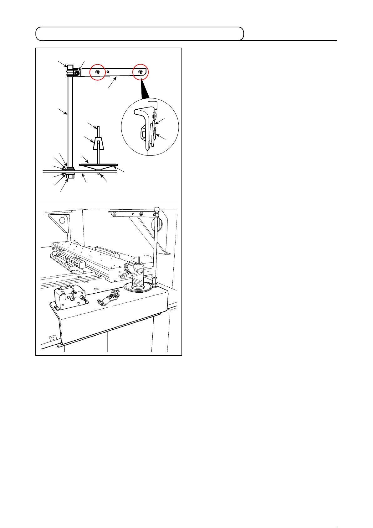
3-7. How to install the thread stand for bobbin winding
1) Pass thread stand arm ❷ over spool rest rod
❸❹
❷
❻
❼
and x with thread stand arm setscrew ❸
❶
and thread stand arm lock nut ❹.
Fit thread stand protection cap ❺ over the top
end of thread stand ❶.
2) Put thread path bush ❻ and thread path ❼ in
holes (two locations) in thread stand arm ❷ in
the written order.
3) Attach spool rest rod lock nut (small) ❽, rub-
ber washer ❾ and thread stand lock washer
to the lower end of spool rest rod ❶. Then, t
the spool rest rod in the hole in bobbin winder
base and x with thread spool rest rod lock
nut (large) .
4) Attach bobbin winder anti-vibrator , bobbin
winder tray cushion and bobbin winder tray
to bobbin winder support rod . Then, x
them on bobbin winder base with a screw.
5) Attach bobbin winder support rod lock plain
washer , bobbin winder support rod lock
spring washer and bobbin winder support
rod lock nut to the section of screw that pro-
trudes from the undersurface of bobbin winder
base and x them.
❾
❾
❺
❶
❽
– 9 –
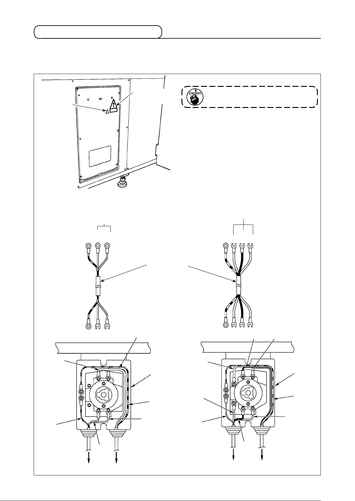
3-8. Connecting the cord
DANGER :
1. To prevent personal injuries caused by electric shock hazards or abrupt start of the sewing
machine, carry out the work after turning OFF the power switch and a lapse of 5 minutes or more.
2. To prevent accidents caused by unaccustomed work or electric shock, request the electric expert
or engineer of our dealers when adjusting the electrical components.
[How to detach the cover]
Remove eight setscrews ❶ of the side cover.
❶
❷
❷
Slowly
[How to open the control box]
Remove six screws ❷ which secure the front
cover of control box. When opening the front
cover, open it by holding it and turning carefully
by approximately 90°until it will go no further, as
shown in the gure.
Be sure to hold the cover with hands
in order to prevent it from dropping.
In this case, do not apply an extra load
to the front cover you have opened.
[How to close the control box]
1) Close the front cover by pushing its lower
side A and x with six screws ❷ while adding
special care not to allow cables to be caught
between the front cover and the control box.
2) Lower downward the cord located on the side
of the control box and cord presser plate C in
A
❸
the push hole B, press the cord and tighten
screws ❸.
C
B
– 10 –
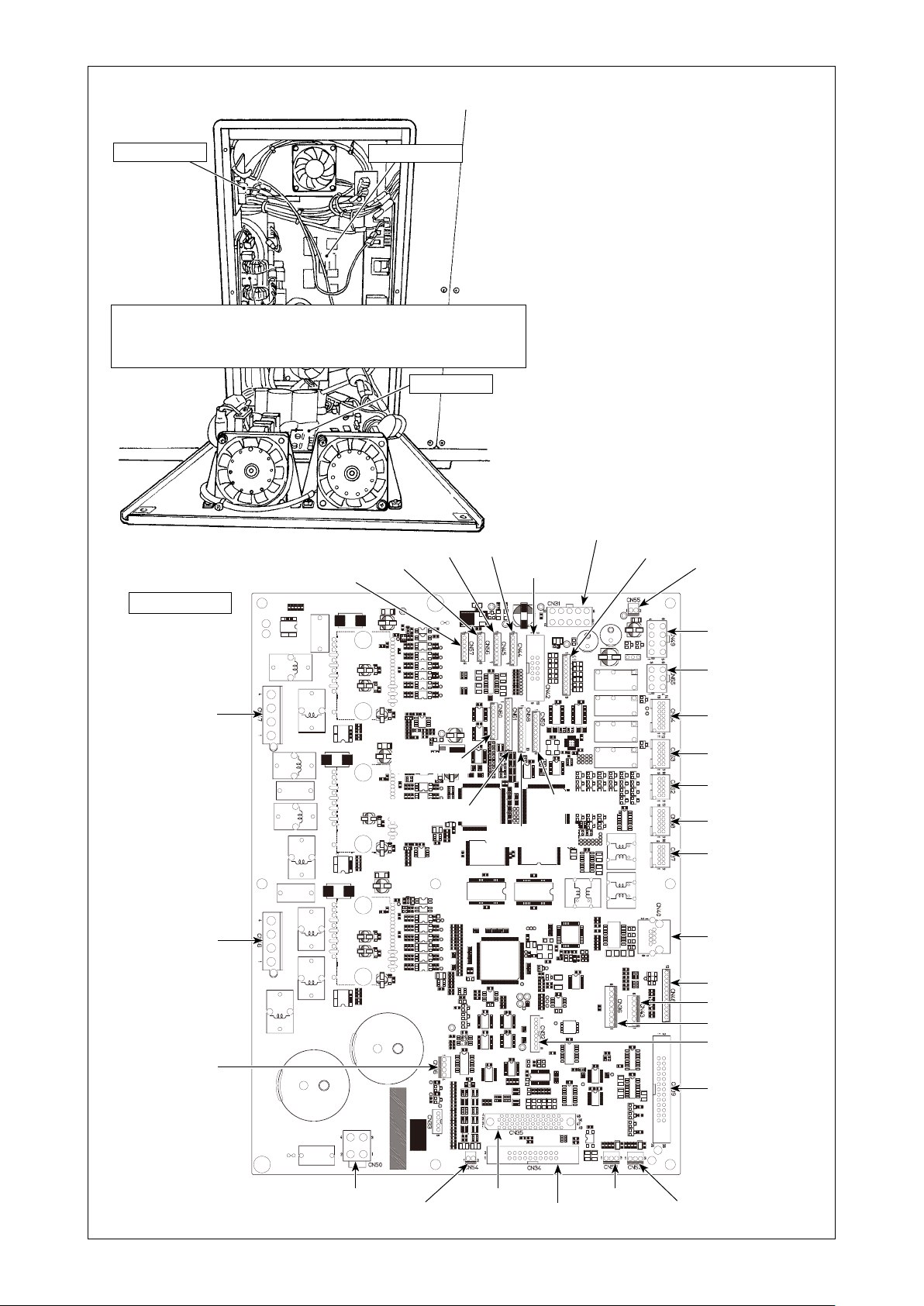
[Inside of the control box]
PWR PCB
MAIN PCB
FLT PCB
FLT-T PCB (single phase 100 to 200V、three phase 200 to 240V)
FLT-S PCB (single phase 200 to 240V)
SDC PCB
CN45 7P
CN56 6P
CN57 6P
CN44 7P
MAIN PCB
CN42 10P
CN31 10P
CN41 9P
CN55 2P
CN47 4P
CN46 4P
CN66 4P
CN60 8P
CN61 12P
CN58 10P
CN49 8P
CN65 6P
CN64 14P
CN63 12P
CN62 10P
CN59 9P
CN38 12P
CN37 10P
CN40 8P
CN48 12P
CN43 6P
CN36 8P
CN32 8P
CN39 26P
CN54 2P
CN35 50P
– 11 –
CN34 20P
CN53 3PCN50 4P
CN52 3P

PWR PCB
CN12 3P
CN13 8P
CN14 2P
CN11 3P
CN16 4P
CN18 10PCN20 2P CN19 10PCN21 2P
CN23 2P
CN22 2P
CN15 3P
CN17 6P
SDC PCB
CN81 2P
CN78 50P
CN77 10P
CN76 10P
CN74 10P
CN73 10P
CN84 5PCN82 12PCN80 8P
CN88 4P
CN87 4P
CN75 4P
CN72 6P
CN71 8P
CN86 4P
CN85 4P
CN70 10PCN79 2P
– 12 –

3-9. Installing the air hose
Open
Close
❶
❷
1) Connecting the air hose
Connect the air hose to the regulator.
2) Adjustment of air pressure
Open air cock ❶, pull up and turn air adjust-
ment knob ❷ and adjust so that air pressure
indicates 0.45 to 0.5 MPa (Max. 0.55 MPa).
Then lower the knob and x it.
* Close air cock ❶ to expel air.
– 13 –
3-10. Cautions for the compressed air supply (source of supply air) facility
As large as 90 % of failures in pneumatic equipment (air cylinders, air solenoid valves) are caused by
"contaminated air."
Compressed air contains lots of impurities such as moisture, dust, deteriorated oil and carbon particles. If such "contaminated air" is used without taking any measures, it can a cause of troubles, inviting
reduction in productivity due to mechanical failures and reduced availability.
Be sure to install the standard air supply facility shown below whenever the machine provided with
pneumatic equipment is used.
Standard air supply facility to be prepared by the user
Air compressor
After cooler
Auto-drain
Air tank
Main line lter
Auto-drain
Air dryer
Mist separator
Filter regulator
Air solenoid valve
Quality of the air supply
When the supply air contains a considerable amount of moisture
Ambient environment
When our machine is installed at a place where the temperature
greatly changes in the morning and in the evening from that in the
daytime or freeze is like to occur
In the aforementioned cases, be sure to install an air dryer.
When the supply air contains a considerable amount of carbon
and dust
(Most troubles in the air solenoid valves are caused by carbon.)
Be sure to install a mist separator.
Standard equipment supplied by JUKI
Air cylinder
Cautions for main piping
• Be
sure to slope main piping by a falling gradient of 1 cm per 1 m in the direction of air ow.
• If the main piping is branched off, the outlet port of the compressed air should be provided at the top part of the piping using a tee in order to prevent drain settling inside
the piping from owing out.
• Auto drains should be provided at all lower points or dead ends in order to prevent the
drain from settling in those parts.
– 14 –
4. PREPARATION OF THE SEWING MACHINE
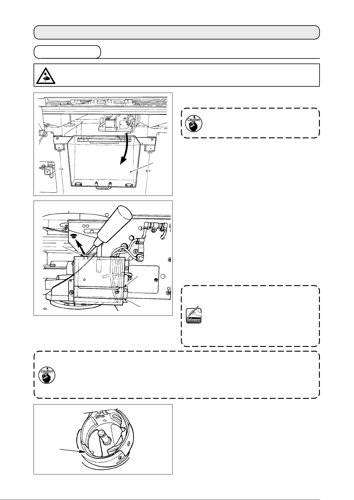
4-1. Lubrication
WARNING :
Turn OFF the power before starting the work so as to prevent accidents caused by abrupt start or
the sewing machine.
1) Open hook section safety cover ❶.
Keep hook section safety cover ❶
closed while the sewing machine is in
operation.
❶
2) Remove rubber cap ❷. Add JUKI New Defrix
Oil No. 2 supplied with the unit into the oil tank.
The oil surface in the oil tank must not exceed
upper line A.
3) Periodically check to make sure that the oil
❷
A
surface in the oil tank remains between lower
line B and upper line A while using the sewing
machine. Fill there with oil using the oiler supplied with the machine as accessories when oil
is short.
The oil tank which is lled with oil is
only for lubricating to the hook por-
B
1. Do not lubricate to the places other than the oil tank and the hook of Caution 2 below.
Trouble of components will be caused.
2. When using the sewing machine for the rst time or after an extended period of disuse,
use the machine after lubricating a small amount of oil to the hook portion. In addition,
use the sewing machine for sewing after having it run idle for approximately two minutes at 1,000 sti/min. (Refer to "III-1-2. Adjusting the needle-to-shuttle relation" p.116 .)
tion. It is possible to reduce the oil
amount when the number of rotation
used is low and the oil amount in the
hook portion is excessive. (Refer to
"III-1-6. Amount of oil supplied to the
hook" p.119 .)
When you use the sewing machine for the rst
time after the purchase, lubricate hook race surface ❸ until a drop of oil can be observed.
❸
– 15 –
4-2. Adjusting the oil quantity in the hook
❶
❷
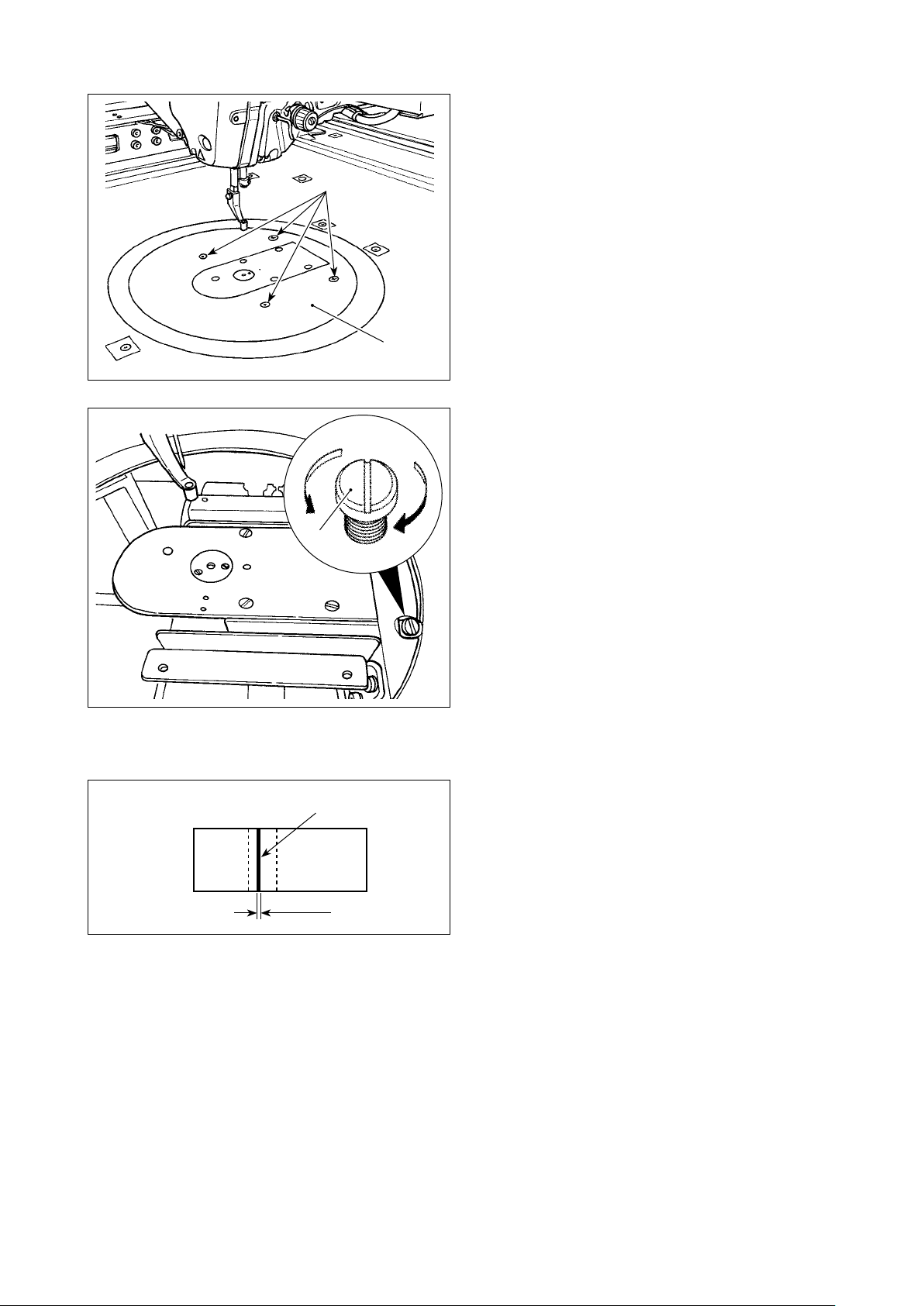
(1) Checking the oil quantity in the hook
1) Loosen setscrews ❶ (right and left). Detach oil
shield ❷.
At this time, do not attempt to forcibly remove
the oil shield. Before removing the oil shield,
turn the pulley until the needle stops at its up-
per end. Then, remove the oil shield.
2) Turn the hook section so that it faces the front.
Paper for checking the oil quantity (oil spots)
①
25 mm
70 mm
Position at which the oil quantity (oil spots) is
②
checked
3 to 10 mm
Oil-spots checking paper
Fit against the wall
* When carrying out the following work described in step 2), take added care not to allow your ngers
to come in contact with the hook.
1) In the case the machine head is cold, run it idle for approximately three minutes. (Low-speed opera-
tion)
2) Insert a sheet of paper for checking the oil quantity (oil spots) in the check position while the sewing
machine is in operation.
3) Check to make sure that the oil surface in the oil tank is at the level between the upper and lower
lines.
4) Check the oil quantity (oil spots) for ve seconds. (Measure with a watch.)
– 16 –
(2) Adjusting the hook oil quantity (oil spots)
❷
1) Remove four setscrews ❷ of round table ❶.
Detach round table ❶.
2) Turn oil quantity adjustment screw ❸ clockwise
until it is fully tightened.
A
3) Turn the screw counterclockwise B by half.
4) The oil quantity (oil spots) is increased by
turning oil quantity adjustment screw ❸ coun-
terclockwise B or is decreased by turning it
clockwise A.
❶
a. Decrease the hook oil quantity when the oil in
the oil tank at the bed side reduces quickly.
b. Decrease the hook oil quantity when the quan-
tity of oil splashing from the hook is large or
Carry out the adjustment in the following cases.
B
A
when oil leaks from the hook cover.
c. Increase the hook oil quantity when the hook
generates a large noise.
❸
d. Increase the hook oil quantity if the needle
thread is not adequately drawn up due to the
oil shortage.
5) After the adjustment of oil quantity, attach
round table ❶ in place and x with four set-
screws ❷.
(3) Sample of proper quantity of hook oil (oil spots)
Proper quantity
Oil splashing from the hook
1 to 2 mm
1) The state shown in the gure represents the
proper quantity of oil (oil spots). Adjustment
may be required depending on the sewing pro-
cess. However, it is important not to excessive-
ly increase/decrease the oil quantity. (Smaller
quantity of oil = Hook seizure (hook becomes
hot); Larger quantity of oil = Oil stains on the
sewn products)
2) Check the oil quantity (oil spots) three times
(with three sheets of paper).
– 17 –
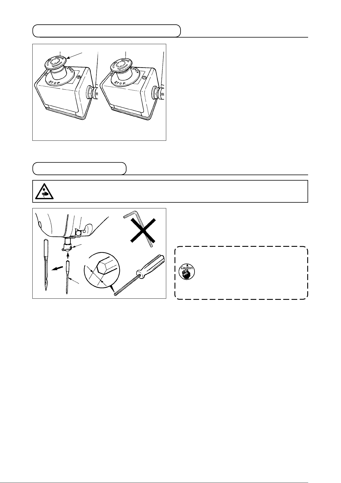
4-3. Checking the emergency stop switch
❶
Emergency stop switch
OFF state
Emergency stop switch
ON state
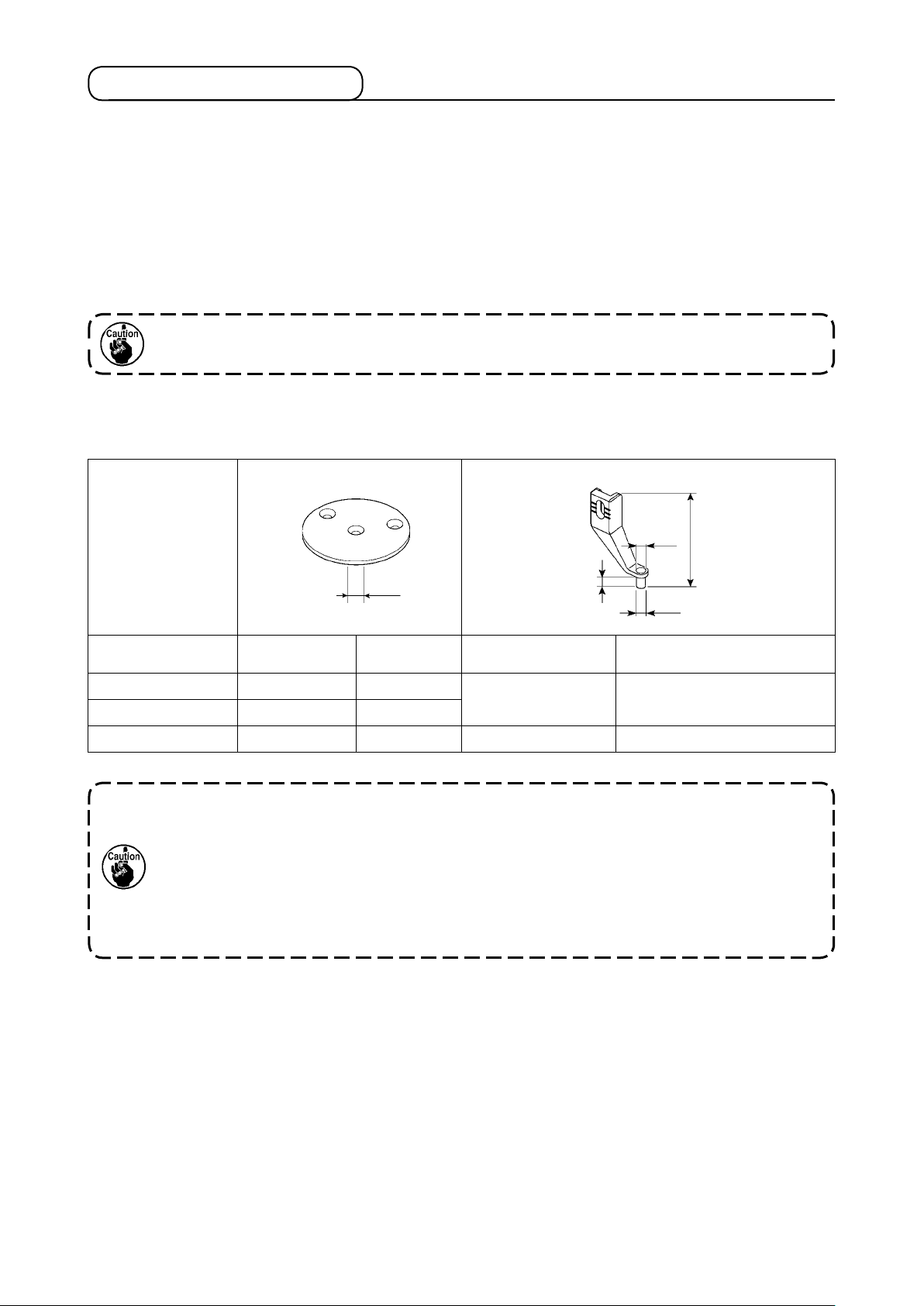
4-4. Attaching the needle
WARNING :
Turn OFF the power before starting the work so as to prevent accidents caused by abrupt start or
the sewing machine.
❶
1.5 mm
❷
When the red button of emergency stop switch ❶
is strongly pressed as far as it goes, the switch is
placed in its ON state. When the button is turned
clockwise, the switch is placed in its OFF state.
Check to be sure that emergency stop switch ❶ is
in its OFF state.
If emergency stop switch ❶ is in its ON state, the
operation panel screen will not light up even if the
power switch is turned ON.
Loosen setscrew ❶. Insert needle ❷ into the hole
in needle bar until it will go no further while facing
its long groove toward the frame. Then, tighten
setscrew ❶.
When tightening setscrew ❶, be sure
to use the screwdriver (Part No. :
40032763) supplied as accessories.
Do not use L-shaped hexagon wrench
key. There is a danger of breaking setscrew ❶.
– 18 –
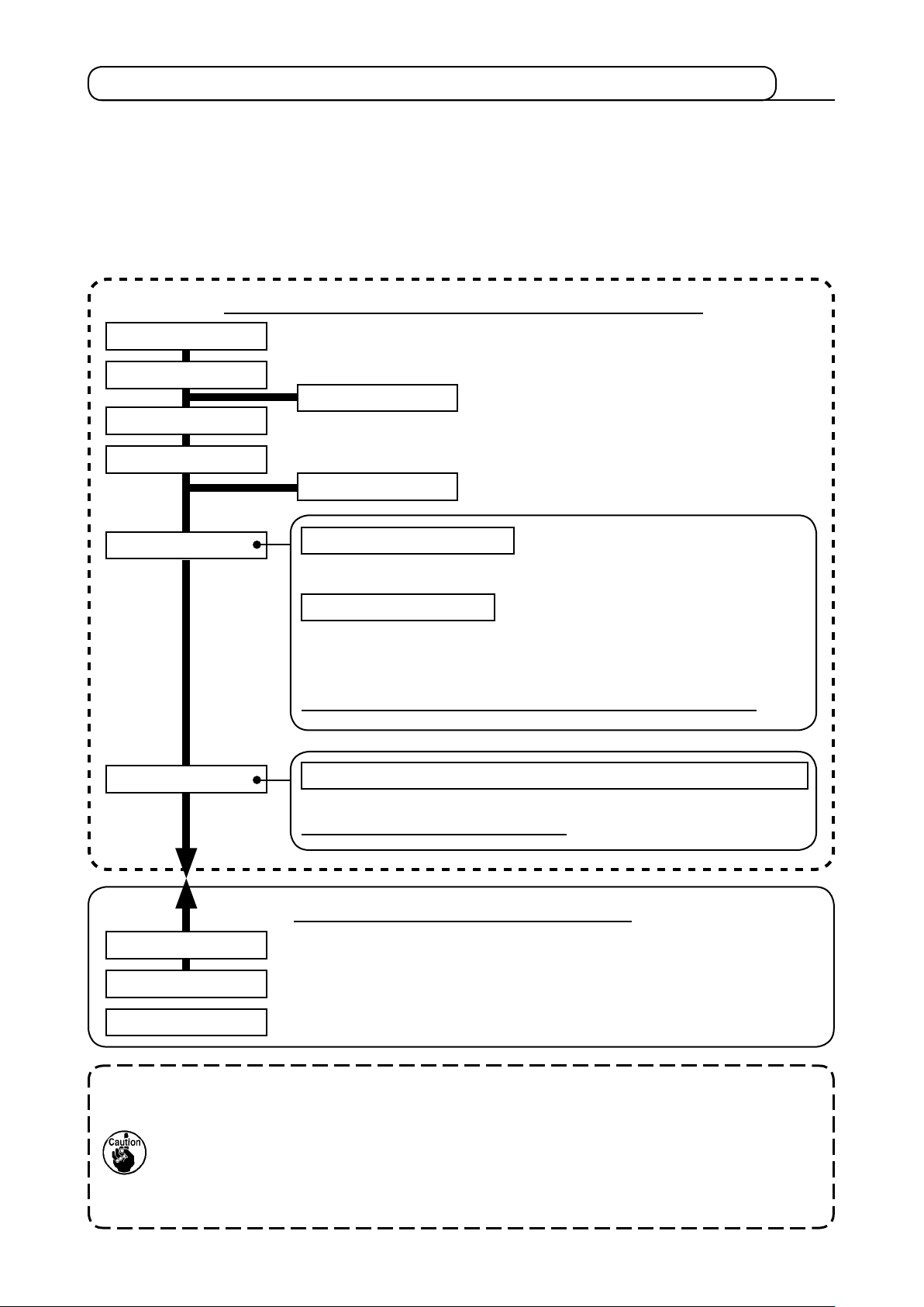
4-5. Needle size and gauge
When changing the needle size, it is necessary to adjust the hook and to replace the gauge.
(1) Adjustment
In the standard delivery state, the hook has been factory-adjusted to DP × 17 #23 needle.
When changing the thickness of the needle, perform the adjustment of
dle-to-shuttle relation" p.116
.
When changing the length of the needle, perform the adjustment of
the needle bar (Changing the length of the needle)" p.115
.
When the adjustment of hook and driver is not t to the thickness of the needle, sewing troubles such as stitch skipping and the like or abrasion of the blade point of hook will be caused.
(2) Gauge
When changing the needle size, replace the gauge with the optional gauge of the correspondence table.
Needle Needle hole guide Intermediate presser
"III-1-2. Adjusting the nee-
"III-1-1. Adjusting the height of
øA
øA
Number (Thickness) Part No.
#18 to #21 14439509 ø2.3 B1601210D0BA ø2.7 × ø4.1 × 5.7 × 38.5
#20 to #23 14439608 ø3.0
#23 or thicker 14439707 ø4.0 B1601210D0CA ø3.5 × ø5.5 × 5.7 × 38.5
Needle hole
diameter (øA)
Part No.
H
L
øB
Dimension
(øA × øB × H × L)
1. The table above describes the typical optional gauges.
For the other special gauges, ask our sales distributors.
2. When using the gauge that is not t for the thickness of the needle, needle breakage,
abrasion of components such as inner hook and the like, sewing trouble such as stitch
skipping and the like will be caused.
Example : When sewing the sports shoes with a big size needle guide or inner hook
presser, needle thread loop becomes unstable and stitch skipping or thread
breakage may occur.
– 19 –
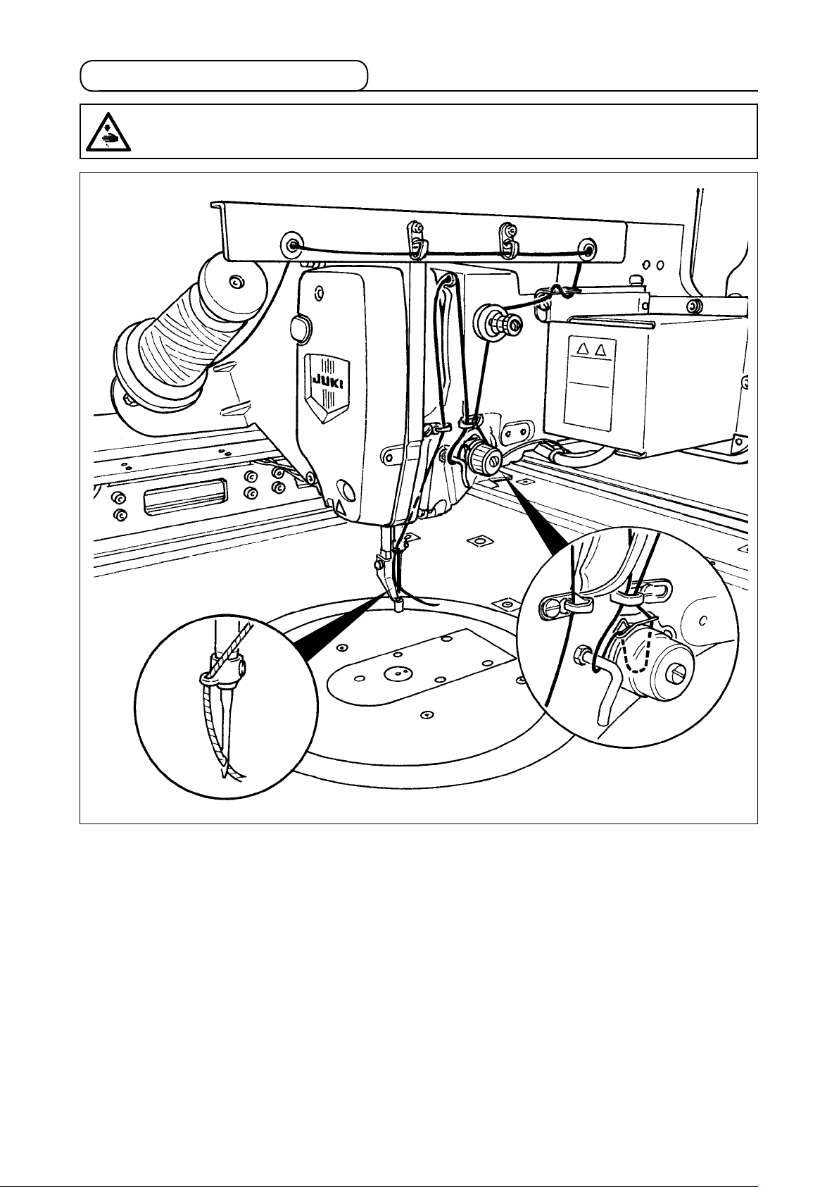
4-6. Threading the machine head
WARNING :
Turn OFF the power before starting the work so as to prevent accidents caused by abrupt start or
the sewing machine.
– 20 –
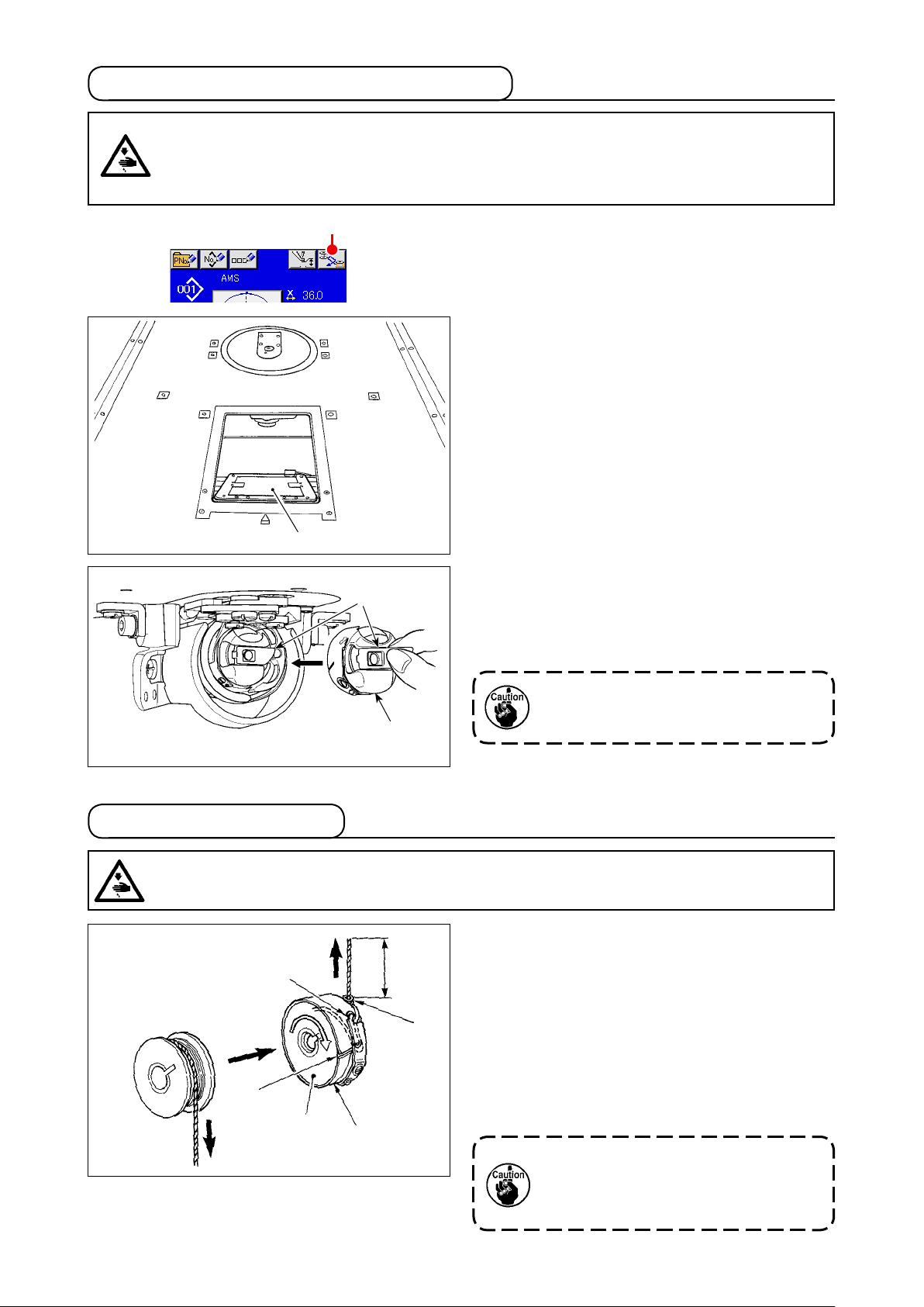
4-7. Installing and removing the bobbin case
WARNING :
Turn OFF the power before starting the work so as to prevent accidents caused by abrupt start or
the sewing machine.
In addition, be sure to close the bobbin replacement cover when re-starting operation in order to
prevent personal injury.
❶
A
❸
1) When button A is pressed, the turning section
rotates to allow the hook to face the front face
and bobbin replacement cover ❶ to open.
2) Raise latch ❸ of bobbin case ❷, and remove
the bobbin case.
3) When entering bobbin case, insert it with the
latch tilted until "click" sounds.
4-8. Installing the bobbin
WARNING :
Turn OFF the power before starting the work so as to prevent accidents caused by abrupt start or
the sewing machine.
❹
❸
❶
❷
❷
4 cm
❺
If bobbin case ❷ is not adequately tted in the hook, it can drop off the hook
or needle can break during sewing.
1) Set the bobbin ❶ into bobbin case ❷ in the
direction shown in the gure.
2) Pass the thread through thread slit ❸ of bobbin case ❷, and pull the thread as it is. By so
doing, the thread will pass under the tension
spring and be pulled out from thread hole ❹.
3) Pass the thread under bobbin thread guide ❺
and draw the thread by 4 cm out from the bobbin thread guide.
If the bobbin is installed in the bobbin
case orienting the reverse direction,
the bobbin thread pulling out will result in an inconsistent state.
– 21 –
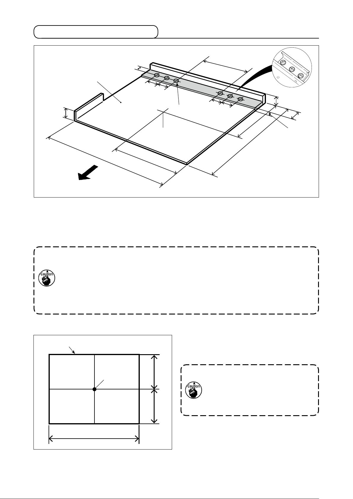
4-9. Preparing the cassette clamp
798 mm
22 mm
360.5 mm
Depth 750 mm (reference)
Weight 9.5 kg or less
8 mm or less
26 mm
Height 5.5 mm
(Chuck plate
mounting base,
height)
Height
12 mm
or less
Operator side
15 mm
(Outside dimension)
Cassette clamp
22 mm
22 mm
22 mm
6×M4
Origin
Width 1,170 mm (reference)
585 mm (reference)
1) The cassette clamp is separately available by a special order.
In the case the customer prepares a cassette clamp, the cassette clamp which is shown in the above
gure must be prepared.
2) Stick a piece of Teon sheet (option: 40123146) or the like on the undersurface of cassette clamp.
1. If a piece of Teon sheet or the like is not stuck on the undersurface of cassette clamp,
the top surface of throat plate can get dirty to cause stains on the sewing material.
The Teon sheet is a consumable part. It is necessary therefore periodically inspect it
and change it with a new one if it has worn out.
2. Clean the undersurface and material retaining surface of cassette clamp and the top
surface of throat plate auxiliary cover before use. After the cleaning, check to be sure
that the aforementioned sections are free from dirt. Then, start using the sewing machine.
[Sewing area]
The sewing area has been factory set to the area
Sewing area
(1,000 x 600) as shown in the gure at the time of
shipment.
In the case of using the sewing area
Origin
300mm300mm
that is 600 mm in longitudinal direction, the cassette clamp may protrude
the throat plate auxiliary cover when
the material is fed in Y direction. So,
be careful.
1,000mm
– 22 –
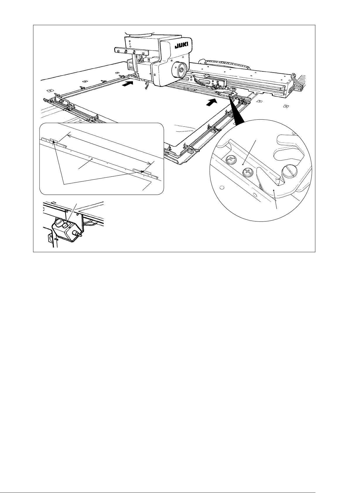
Chuck plate mounting pitch
782 mm
❶
❷
❹
❷
❸
3) Temporarily x chuck plates (40181516) ❷ at the 782-mm pitch positions of cassette clamp ❶ with
setscrews and washers. (Chuck plates, setscrews and washers are packed in the accessory box.)
4) While tting chuck plate ❷ against chuck ❸, attach the cassette clamp in place. Then, securely x
chuck plates ❷ with setscrews.
To detach the cassette clamp, press eject switch ❹ (blue).
5) Attach and detach the cassette clamp several time in repetition to check whether it can be complete-
ly attached in place.
After attaching the cassette clamp in place, move it back and forth to check whether there is a back-
lash.
– 23 –
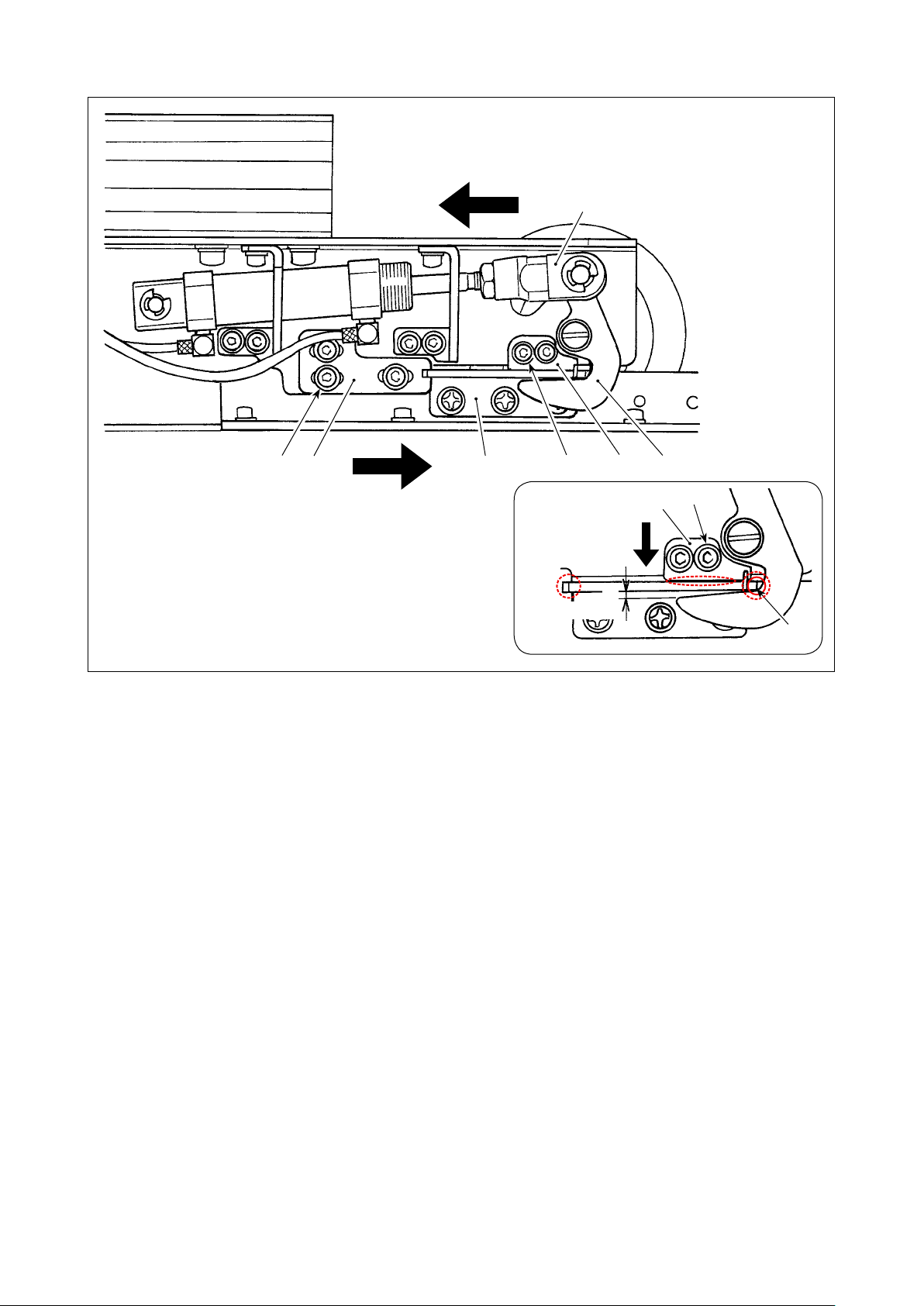
[In the case there is a backlash]
Releasing side
❼
❽❾ ❸❺❻ ❷
Fig. I
B
0.5 to 1 mm
❽
❾
A
1) Loosen screws ❻ (3 pieces). Press chuck plate bracket A ❺ against chuck plate ❷ of the cassette
clamp and x with screw ❻.
Adjust the position of chuck plate bracket A ❺ also on the opposite side in the same manner. At this
time, adjust so that right and left chuck plates ❷ and chuck plate brackets A ❺ are symmetrically
positioned.
2) Then, pressing cylinder knuckle ❼ toward the releasing side, loosen screws ❾ (2 pieces) of chuck
plate bracket B ❽. Adjust the positional relationship between chuck plate ❷ and chuck ❸ so that
they are positioned as illustrated in Fig. I.
Adjust, by pressing chuck plate bracket B ❽ in the direction of the arrow, so that a clearance of 0.5
to 1 mm is provided in section B when the chuck is aligned with the chuck plate at section A. Then,
x the chuck plate B with screws ❾.
* Apply JUKI Grease A to the contact section indicated in a dotted circle in Fig. I.
– 24 –
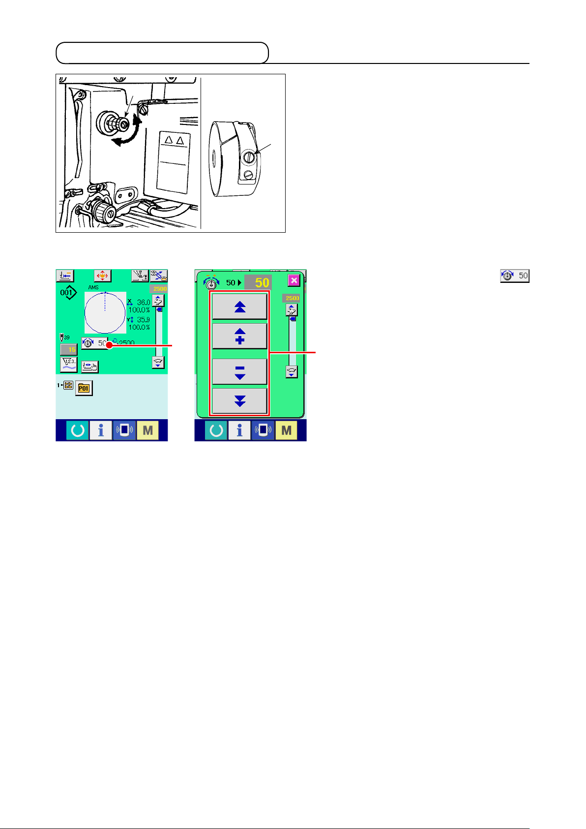
4-10. Adjusting the thread tension
❶
Longer
Shorter
[Adjusting the needle thread tension]
A
❷
If thread tension controller No. 1 ❶ is turned
clockwise, the length of remaining thread on the
needle after thread trimming will be shorter. If it is
turned counterclockwise, the length will be longer.
Shorten the length to an extent that the thread is
not slipped off.
Adjust needle thread tension from the operation
panel and bobbin thread tension with ❷.
1) Select THREAD TENSION button
in the sewing screen.
A
2) Set needle thread tension with SCROLL
button B. There is a setting range of 0
to 200. When the set value is increased,
B
the tension becomes higher.
* When the set value is 50 at the time of
standard delivery, the thread tension is
adjusted to 2.35N (spun thread #50).
(When thread tension No. 1 is released)
– 25 –
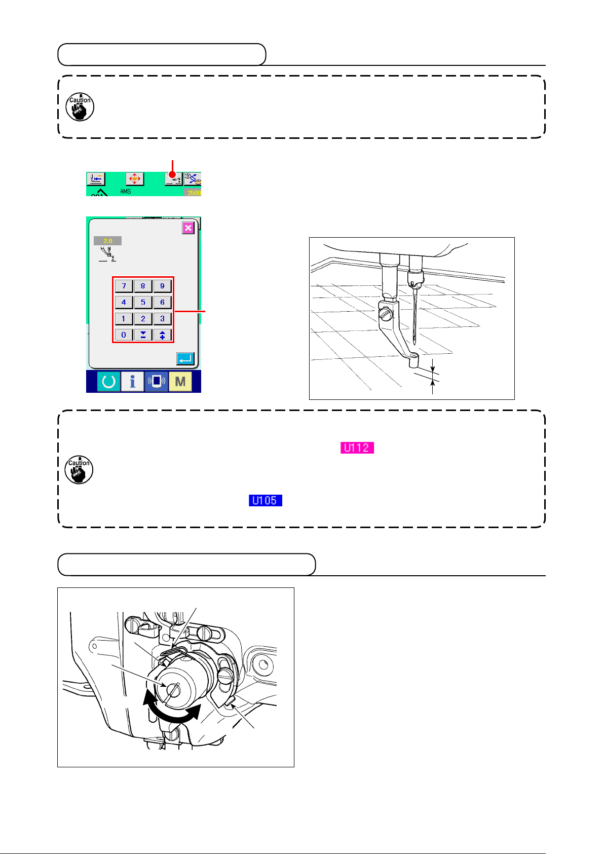
4-11. Intermediate presser height
1. When raising the intermediate presser height, turn the pulley by hand to lower the needle
bar, and conrm that the needle bar does not interfere with the intermediate presser.
2. Take care not to allow your hands and ngers to be caught in the cassette clamp or the
intermediate presser.
A
Press INTERMEDIATE PRESSER SETTING button A and adjust with TEN keys B so that the clearance between the bottom
end of intermediate presser and the cloth is 0.5 mm (thickness
of thread used).
B
0.5 mm
1. Setting range of the intermediate presser is up to the standard of 3.5 mm.
However, when using DP × 17 needle for H type or the like, the setting range can be
changed up to max. 7 mm with memory switch .
2. When increasing the height of intermediate presser or making the needle size thicker,
conrm the clearance between the wiper and the components. Wiper cannot be used
unless the clearance is secured. In this case, turn OFF the wiper switch, or change the
set value of memory switch .
(Wiper is optionally available.)
4-12. Adjusting the thread take-up spring
1) Adjusting the stroke
❸
❹
Increase
❶
Decrease
❷
Loosen setscrew ❷, and turn thread tension asm.
.
❸
Turning it clockwise will increase the moving
amount and the thread drawing amount will
increase.
2) Adjusting the pressure
To change the pressure of the thread take-
up spring ❶, insert a thin screwdriver into the
slot of thread tension post ❹ while screw ❷
tightened, and turn it. Turning it clockwise will
increase the pressure of the thread take-up
spring. Turning it counterclockwise will decrease the pressure.
is
– 26 –
 Loading...