

JUKI AMS-224EN6030R/AW-3, AMS-224EN4530R/AW-3 Instruction Manual

AMS-224EN4530R / AW-3
AMS-224EN6030R / AW-3
INSTRUCTION MANUAL
1

CONTENTS
1. GENERAL ............................................................................................... 1
1-1. Specications of AW-3....................................................................................................... 1
1-2. Conguration......................................................................................................................2
2. INSTALLATION ....................................................................................... 4
2-1. Installation procedure........................................................................................................4
2-2. Installation location ...........................................................................................................9
3. OPERATION PROCEDURE ................................................................. 10
3-1. Attaching / removing the cover ......................................................................................10
3-2. How to thread the device with the bobbin thread ......................................................... 11
3-3. How to set a bobbin ......................................................................................................... 12
3-4. Length of remaining thread to be removed ................................................................... 13
3-5. Device operation lamp ..................................................................................................... 14
3-6. To use the AW-3 ................................................................................................................15
3-7. Behavior of the AW-3 device when the power is turned ON ........................................ 16
3-8. Basic operation and setting ............................................................................................ 17
3-9. Operating the AW ............................................................................................................. 18
3-10. Setting the AW number-of-stitches input mode, AW operation mode and
remaining-thread allowance length ................................................................................ 21
3-11. Example of operation ..................................................................................................... 26
3-12. Turning OFF of the power ............................................................................................. 30
3-13. Error display and error handling procedure................................................................ 30
3-14. Detection of errors related to the AW ........................................................................... 32
3-15. List of errors ................................................................................................................... 34
4. MAINTENANCE .................................................................................... 36
4-1. Attaching / removing the cover ......................................................................................36
4-2. Cleaning ............................................................................................................................ 36
4-3. Replacing the fuse ........................................................................................................... 38
4-4. Replacing the gripper tube..............................................................................................38
4-5. Corrective measure against idling of the bobbin.......................................................... 39
4-6. Adjusting the air ow for the remaining thread guide ................................................. 39
5. TROUBLESHOOTING .......................................................................... 40
i

1. GENERAL
Conventionally, a series of operations including the replacement of bobbin in the sewing machine hook,
removal of thread remaining on a bobbin, winding of a bobbin, threading of bobbin case tension spring,
and trimming of thread have been carried out manually. Now, this device has been developed to carry
out the series of operations full-automatically. This device not only helps increase efciency of sewing
work but also achieves stable product-making in the process that requires high-quality seams.
Refer to the Instruction Manual for the AMS-224EN4530R/IP-420 for the main body of sewing machine.
1-1. Specications of AW-3
1 Applicable bobbin, bobbin
case
2 Applicable thread count #5 to #30 (Japan), 150 to 50 (TEX), 18 to 60 (TKT)
3 Applicable type of thread Synthetic thread
4 Remaining-thread removal and
bobbin winding operation
5 Condition setting according
to the thread type
6 Line voltage 100,120/200,220,240 Vac ±10 %, Single phase 50/60 Hz
7 Power consumption 100 VA
8 Air pressure used 0.5 MPa
9 Air consumption 156 Nℓ / min (max. value)
10 Dimensions
11 Mass of the device 10 kg or less (The main body only. The thread draw-out unit and
12
Operating temperature range
Exclusive double-capacity bobbin and bobbin case.
Possible while the sewing machine is in operation.
Conditions to be met to unravel the thread at the beginning of
winding a bobbin can be set.
350 mm (W) × 290 mm (L
control box are excluded.)
5 ˚C to 35 ˚C
)
× 270 mm (H
)
13
Operating humidity range
14 Noise - Equivalent continuous emission sound pressure level (LpA) at
35 % to 85 % (No dew condensation)
the workstation : A-weighted value ≦ 75 dB ; (Includes KpA =
2.5 dB) ; according to ISO 10821- C.6.2 -ISO 11204 GR2 at
remaining-thread removal length = 2 m; Bobbin-thread winding
length (22 m).
– 1 –

1-2. Conguration
❷
❶
❽
❹
❺
❾
❸
❼
❻
– 2 –

Name Function
Device main unit It is mounted under the sewing machine bed and is the mechanical
❶
section of the device which carries out changing of bobbin, removal of
thread remaining on the bobbin, bobbin winding, threading and thread
trimming automatically.
Cover It is used for preventing the worker from coming in contact with the
❷
moving section of device.
Bobbin setting section It is the transit place used in the case of putting/removing a bobbin on/
❸
from the device.
Carrier arm It is the mechanism for carrying a bobbin case to the hook, bobbin
❹
setting section, remaining thread removal section and bobbin winding
section.
Bobbin case chuck unit It is the mechanism for grasping the bobbin case and loading/remov-
❺
ing it in/from the hook. It is mounted at the top end of the carrier arm.
Remaining thread remov-
❻
al section
Thread unraveling section This mechanism unravels thread which is wound at the beginning. It
❼
Bobbin-thread winding
❽
section
Nozzle Thread from the bobbin thread cone comes out from the tip of nozzle
❾
Bobbin thread feeding unit This is the unit for feeding the thread bit by bit from the tip of nozzle
Dust bag It is the bag in which the remaining-thread removed from the bobbin is
Control box of the device It is the box which contains the PCB that controls the device operation.
Operation panel This panel is used for setting bobbin-winding/-changing conditions and
It is the mechanism for removing the thread remaining on the bobbin
taken out from the hook. It consists of the remaining thread removal
roller, suction vacuum, etc.
consists of a thread unraveling roller, etc.
It is the mechanism for newly winding thread on a bobbin, threading
the bobbin case and trimming the thread. It consists of the clutch plate,
threader, thread trimming knife, etc.
by way of thread path.
The thread coming out of the nozzle is wound on a bobbin.
and for accurately measuring the length of thread wound on a bobbin.
stored.
This control box is different from the one for the sewing machine.
carrying out bobbin-insertion/-removal operation.
Its function is common to that of the operation panel for the sewing
machine.
Device operation lamp It indicates that the device is in operation.
– 3 –

2. INSTALLATION
2-1. Installation procedure
Read the Instruction Manual for the main body of sewing machine when installing the device.
2-1-1. Remove packing material from the sewing machine.
2-1-2. Table position adjustment: Only for 6030
For the 6030, the table has been retracted from the normal position in the factory in prior to ship-
ment.
After unpacking, be sure to carry out the following steps 1) through 9).
DANGER :
The power cable passes through inside the cover. The terminal block is also installed inside
the cover. Be sure to turn the power OFF before starting the installation work in order to protect
against accident caused by electric shock.
L
Position adjustment for the
left table L is described as an
example. Adjust the position of
R
the right table R in the similar
manner.
[Accessories to be used]
A
B
A
: Table xing bolt cover
HX00326000B x 2
B
: Power switch setscrew
SK3512001SE x 2
(Four setscrews are used for the table of the
machine for JE.)
1) Remove screws ❶ and ❷ to remove the cover.
* When removing screw ❷, take care not to lose
the nut secured on the underside of the table.
❶
❷
– 4 –
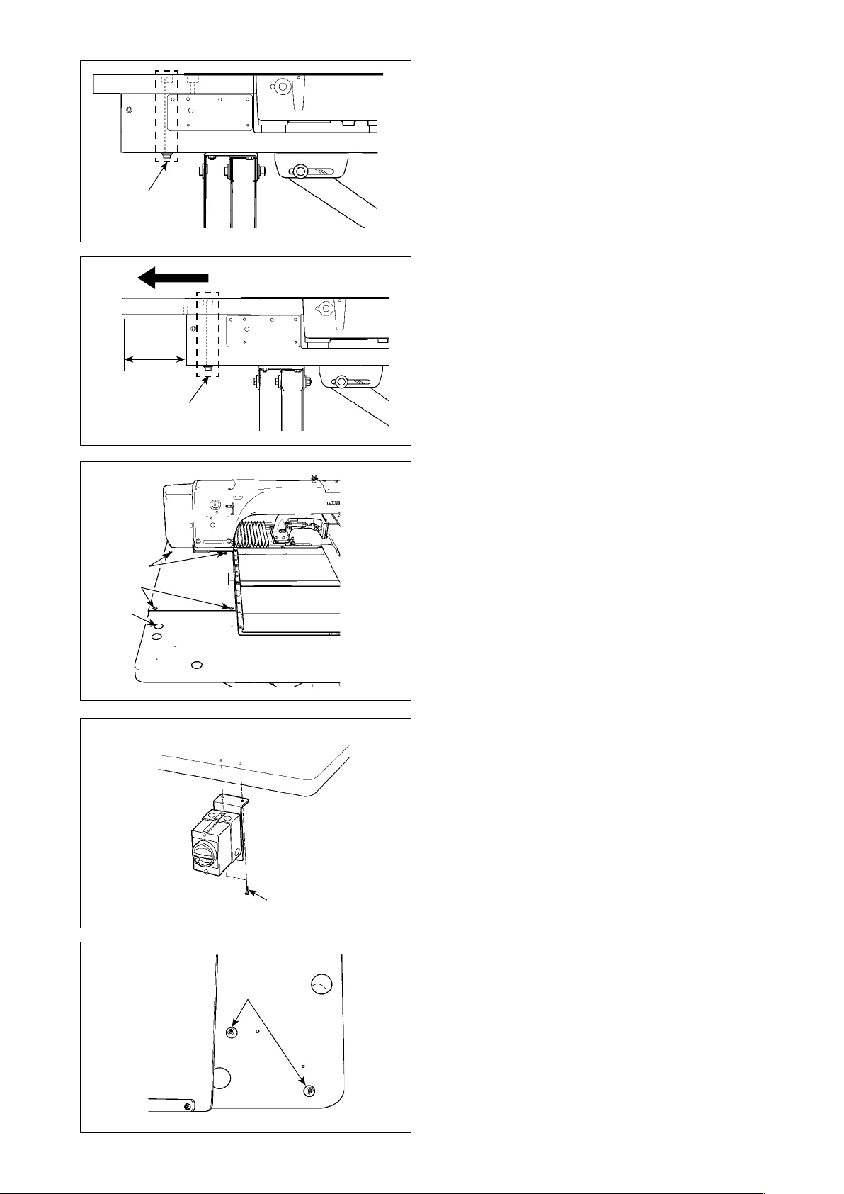
❸
175mm
❶
❷
A
❸
2) Remove table xing bolts ❸ which are mounted
at two locations of the table stand.
* The following steps 3) through 7) are the re-as-
sembly procedure of the table.
3) Shift the table to adjust so that it laterally pro-
trudes from the end of the table stand by 175
mm. For the longitudinal direction, also adjust so
that the table protrudes equally (approximately 3
mm on each side) from the end of table stand.
* If the table is not correctly positioned in the
longitudinal direction, the throat plate auxiliary
cover may not be removed.
4) Temporarily x table xing bolts ❸ at two loca-
tions from the table stand side.
5) Tighten screws ❶ and ❷ to mount the cover.
* If the cover and tapped hole do not align, align them
by moving the table.
* Tighten screw ❷ after mounting the nut from the
underside of the table.
6) Securely tighten the table xing bolts at two
locations from the table stand side. (For refer-
ence: Tightening torque: 6 N•m)
7) After mounting the cover, attach the table xing
bolt cover (accessory A) in position.
D, E
8) Secure the power switch at the punched loca-
tion on the lower right part of the table using
wood screw (accessory C).
C
9) Secure the operation panel stoppers (accessory
D
) in the punched locations at near side of the
right table using wood screws (accessory E).
– 5 –
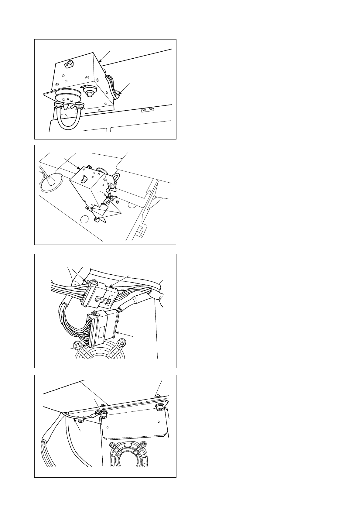
2-1-3. Attaching the feed unit
❶
❶
1) Connect the tube ❷ to the joint of feed unit
❶.
❷
2) Attach feed unit ❶ to the table with three
wood screws ❸. Threaded sections in the
table have prepared holes.
❸
❺
❹
❽
❾
❻
3) Connect cable connectors ❹ and ❺ of feed
unit ❶ to connectors ❻ and ❼ on the table
stand side.
❼
4) Connect FG cable ❽ of feed unit 1 to control-box mounting screw section ❾.
– 6 –
5) Pass nozzle thread guide tube through
table hole .
6) Fix nozzle thread guide tube on the un-
dersurface of the table hole with cable clip
band . Drawing nozzle thread guide tube
downward, x cable clip band with pressed
against the table so as to prevent nozzle
thread guide tube from uctuating.
Cut out the excess of cable clip band .
7) Connect the other end of nozzle thread guide
tube to nozzle joint .
8) Fit cable clip band cover over the cable
clip band section of nozzle thread guide tube
.
– 7 –
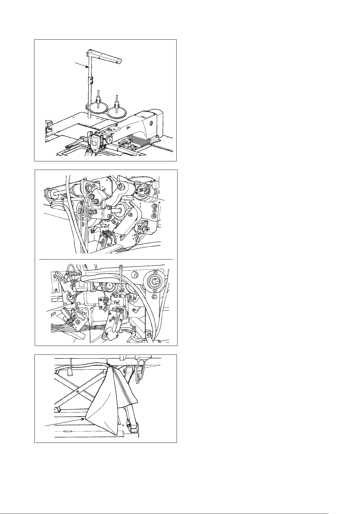
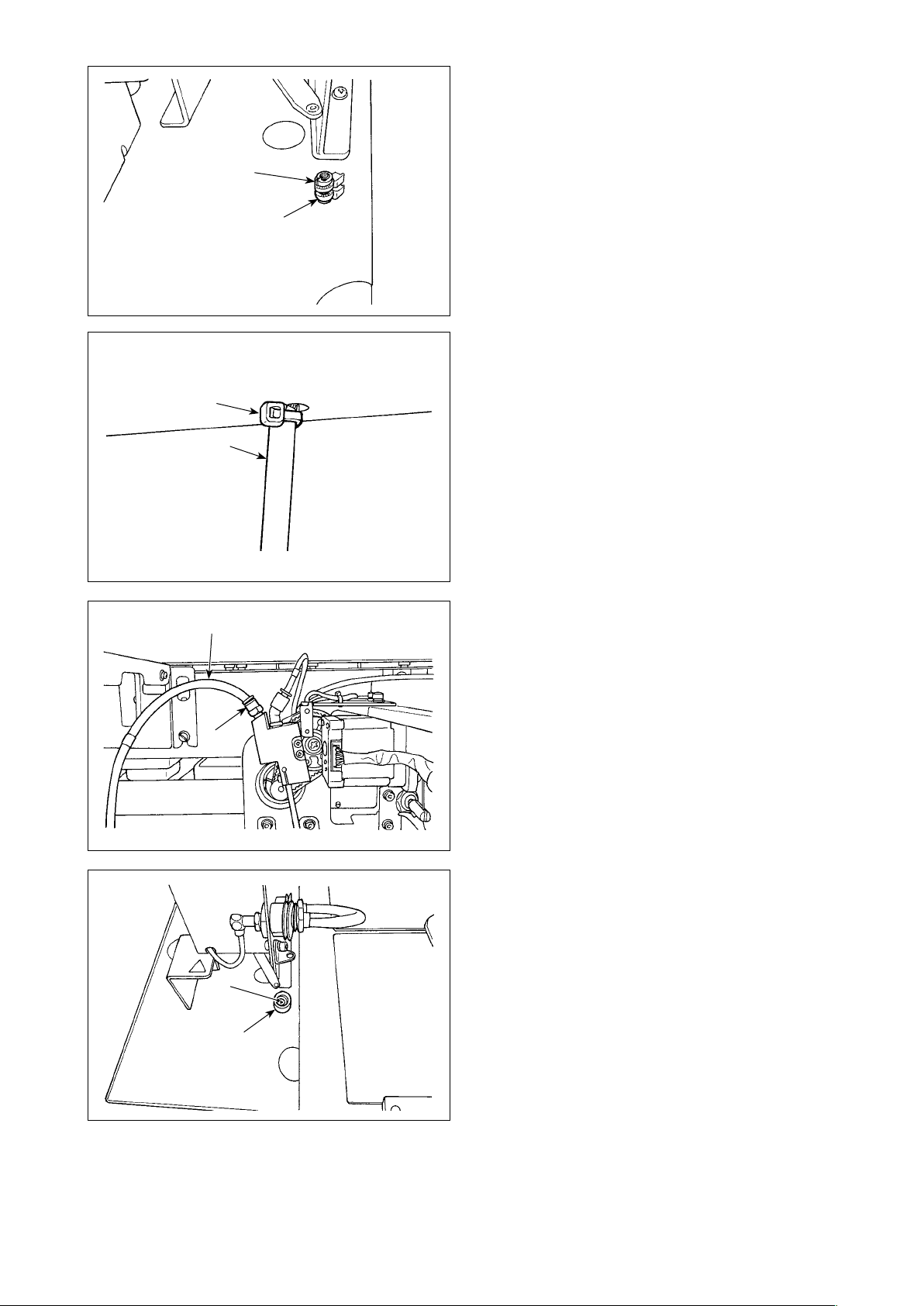
2-1-4. Preparing the AW-3
❶
❷
1) Install thread stand ❶ on the sewing-ma-
chine table.
2) Cut vinyl string which is used for securing the
carrier arm ❷.
3) Cut plastic string which secures the nozzle
❸.
❹
❸
4) Take out dust bag ❹ from the accessory box.
Attach it to the table stand.
– 8 –
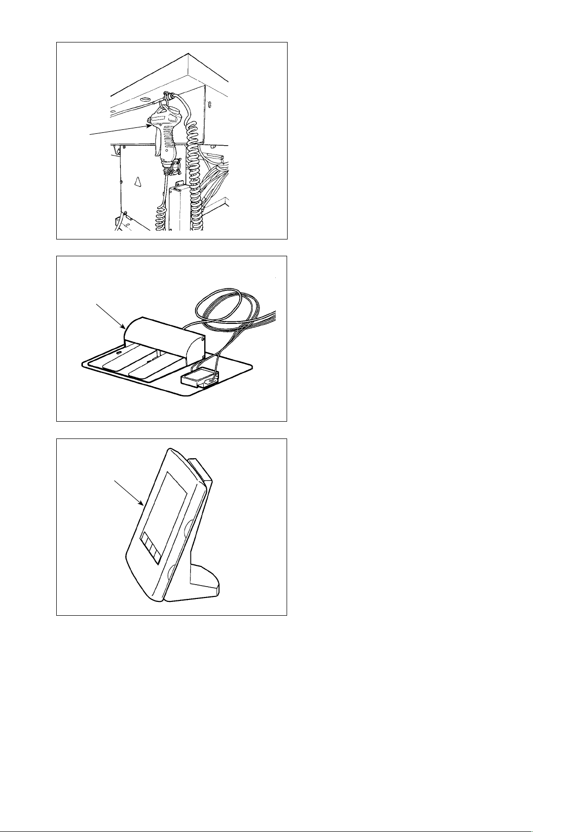
❺
5) Remove the adhesive tape which is used for
xing air gun ❺.
6) Take out pedal ❻.
❻
7) Take out panel ❼.
❼
2-2. Installation location
Carefully check the following with respect to the installation location.
(1) This device uses an optical sensor. In order to protect the optical sensor from malfunctioning, do
not install the device at a place such as the place near the window that is exposed to the direct
sunlight. In addition, determine the orientation of the device to avoid the direct sunlight.
(2) Do not use the device at a place near equipment that generates large electrical noise in order to
prevent a malfunction. In addition, it is preferable to install the power supply line away from the
aforementioned equipment.
– 9 –
3. OPERATION PROCEDURE
CAUTION :
Turn OFF the power before starting the work so as to prevent accidents caused by abrupt start of
the sewing machine.
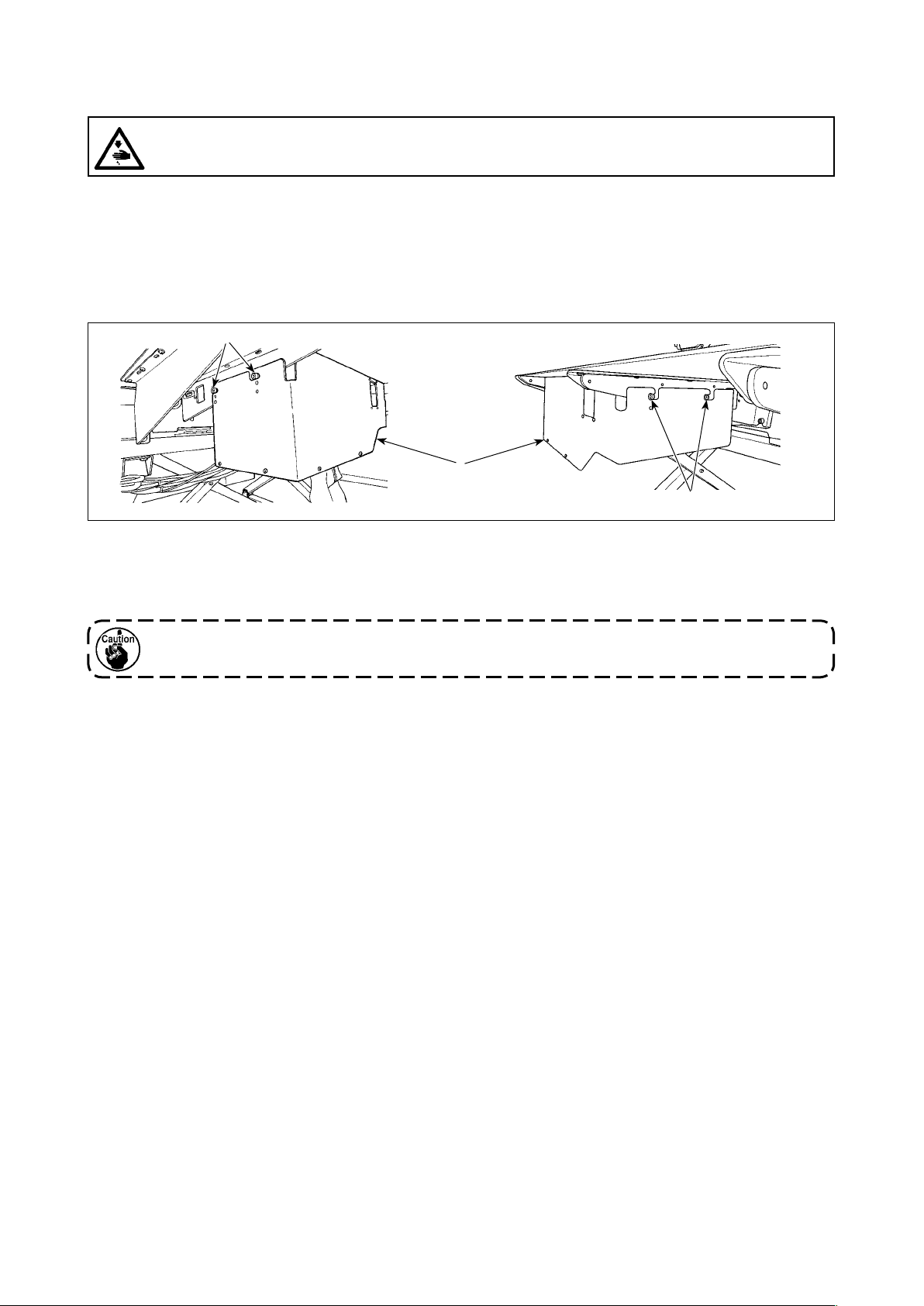
3-1. Attaching / removing the cover
It is necessary to remove the front cover ❶ in order to set up the bobbin thread or carry out maintenance. Remove the cover ❶ as described below.
❷
❶
❷
1) Loosen four setscrews ❷ on the right and left side faces of the device.
2) Slightly shift the cover ❶ upward, then carefully draw it toward you.
Install the cover ❶ reversing the removal procedure.
Be sure to attach cover ❶ for the sake of safety when performing sewing.
– 10 –
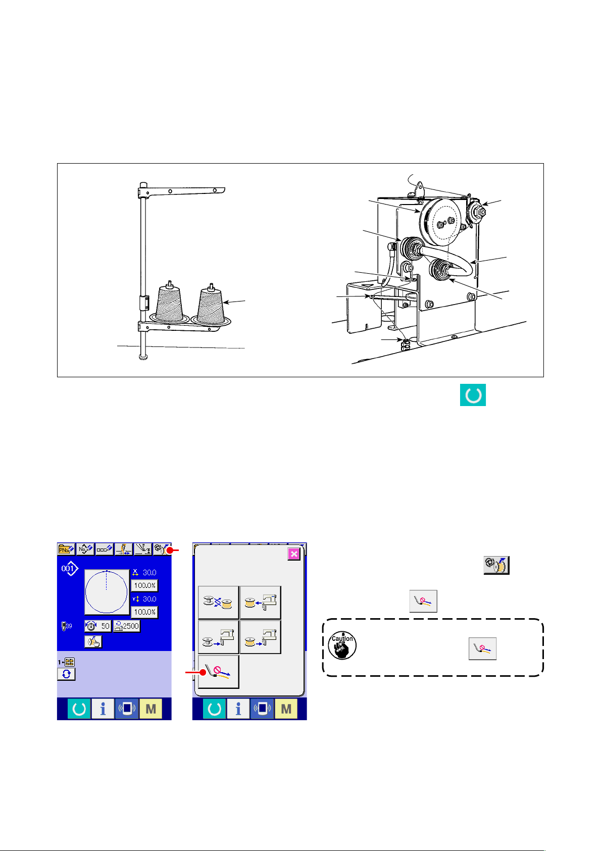
3-2. How to thread the device with the bobbin thread
In order to accurately measure the length of thread from the bobbin thread cone ❶ to be wound on a
bobbin, guide the thread from the bobbin thread cone ❶ through the bobbin thread feeding unit and
draw the thread out from the nozzle as illustrated in the gure.
Install the spool holder disk to the lowest possible position. If it is installed at a high position, an excessive tension will be applied to the thread drawn from the bobbin thread cone ❶, causing a trouble.
❷
❾
❹
❶
❸
❺
❻
❼
❽
1) Insert the power plug to a receptacle and turn ON the power to the device. Press . Wait until
initialization operation of the device is completed. (Approx. 10 seconds)
2) Pass the thread drawn from bobbin thread cone ❶ through thread tension controller ❷.
3) Wind the thread on thread length measuring roller ❸ by one layer.
4) Pass the thread through thread guide ❻ by way of tension controllers ❹ and ❺.
It should be noted that the tube extending between thread tension controllers ❹ and ❺ is intended
to prevent thread from tangling on the shaft of the respective thread tension controllers. Pass the
thread through the space inside the curved part of tube ❾.
5) Pass the thread through the hole in the tip of thread feed arm ❼.
A
B
<Data input screen> <AW operation screen>
– 11 –
6) When the data input screen is displayed
on the operation panel, press A.
When the AW operation screen is dis-
played, press B.
Be aware that the thread feed arm
❼ may operate when B is
pressed.
 Loading...