

Page 1

•JUKI
Medium-sized
Computer-controlled
ENGINEER'S
Cycle
Machine
MANUAL
Page 2

PREFACE
This Engineer's Manual is written for the technical personnelwho are responsible for the service and maintenance
of
the
machines.
The Instruction Manual for these machines intended for the maintenance personnel and operators at an apparel
factory contains detailed operating instructions. And this manual describes "How to Adjust", "Results of Improper
Adjustments", and other information which are not covered by the Instruction Manual.
Itisadvis^letouse
carrying
This
"HowtoAdjust",
<xit
manual
the maintenanceofthese machines.
mainly
the
pertinent
consistofthree
andthe
third,
Instruction
sections;
"ResultsofImproper
Manual
the
first
and
Parts
List
section
Adjustment."
presents
together
"Standard
with
this
Adjustment",
Engineer's
the
Manual
second
when
section,
r
r
r
Page 3

CAUTION
X
1. When a pattern
winder
turned
automatically.
the
away from
in operation.
3.
switchorthe
ON,feeding frame O
feeding
During
operation,be careful not to
change
So,
frame.Besuretokeep
the
feeding frame while
feeding
never
is made, or
frame
comes
put
your
the
bobbin
switch
is
down
fingers
under
your
fingers
the
machine is
allow
your or any other person's head or hands to come close to the
Be
suretoturn
removing belt cover O
Do
cover
handwheel, V belt or motor. Also, do not place anything near any of
Doingsomay be
dangerous.
not
removed.
the
operate
these
power
switch
OFF
before
and
the
Y travel
machine
with
shaft
the
cover
belt
parts while is in operation.
4. Ifyour machine is equipped whit a belt cover, eye guard or any other protections, do not operate your
machine with any of them removed.
Page 4

CAUTIONS
BEFORE
OPERATION
1. Remove bed fixing bolt O before starting
operation.
When
transporting
fixing bolt
3.
Precautionsinhandling
Do
food
not
and
0>
place
drink.
the
your
floppy
AMS-215C,
floppy
disks
disk
nearanashtray
Install
bed
RIter
2.
Clean
the
filterofthe
Do
not
touch
or
the
fan
exposed
[13HI
once
every
partsofthe
week.
floppy
disk.
CjD
Do
not
material.
bring
the
floppy
disk
=3;
12
closetoa
magnetized
4.
Do
not
or
higher)ora
The
sewing
(In
the
the
pulley
the
reverse
place
the
floppy disk In a
place
machine
directionofthe
side.
Never
direction.
hot
exposedtodirect
should
run
counterclockwise
arrow)asobserved
allow
the
machinetorun
place (51*0
sunlight.
from
In
Page 5

5.Besureto
the bed, be sure movethe feeding frame to the
6.
Before
applyafew
surface
supply
starting
dropsofthe
0.
oil
the
until
the
machine
lubricating
oil
which
level
has
oil
reaches
been
tothe
red
marksQaic*
left.)
newiy
set uporhas not
crank
assembly
0
through
Be
sure
to load or unload floppy disk O whilethe
power is ON. if
turnedONor
the
data
storedinthe
®''
gauge.
been
used
foralong
holeO,one
the
power switch should be
OFF
with
droptoracing
the
floppy
disk
maybedestroyed.
(When
lubricating
periodoftime,
disk
mounted,
8. The
AMS-215Cisprovided
which
[When
detected
So,
sometimes
extends
inputting
with
beyond
accuracy.
pattern
data
the
using
data
with
sewing
the
the
main
area
main
(180mmx
unit
whichislarger
unit
input
input
thanthe
function
110
function,
sewing
as standard,
mm)
cannot
the
travel
areaspecified
besewnevenif
limit
however,asewing
inputting
ofthe
sewing
area
maybecreated.
pattern
it.
cannot
be
Page 6

9. To raise the sewing machine, attach grip O supplied withthe sewing machine and raise the sewing
machine
Be
in
the
suretouse
%
direction
stopper
of
the
arrow.
0 when working with
the
sewing machine raised.
10.
When
the
switched
the
thread
completed
disk
will
threader
ON,
tension
the
open.
sew
thread
and
the
desired
disk
trimming,
sewing
closed.
machine
sewing
Once
the
are
pattern
you
thread
with
have
tension
X
Closed
1 f//
oi
Opened
11. When polyethylene oiler O
oil,
removeitand
12.
Priortooperation,besuretoclose
box
cover
In order to prevent
into
the
control
may
leadtomalfunctionsorfailures.
box.
drain
the
Dust
becomes
oil.
dust
into
the
filled with
the
control
from getting
control
box
(Don't
Opem
Page 7

CONTENTS
1.
FEATURES
Z
SPECIFICATIONS
3.
OPERATION
3- 1. Names of the main components 6
3- 2.
Control
3-3.
Operation
3-4.Other
3- 5.
Checking
3- 6. Operation procedure 14
3- 7.
Precautions
4.
DESCRIPTION
4-1.
Sewing
4- 2. Control box 23
4-3.
Operation
4- 4. Motor 26
5.
ADJUSTMENTS
5-1.
Mechanical
5- 2.
Electrical
5-3.
Rotary
box
panel
switches
before
during
OF
machine
panel
parts
parts
DIP
switches
panel
EACH
operation
operation
MAIN
for
COMPONENT
setting
the
test
mode
1
3
6
8
10
12
13
20
21
21
25
27
27
1
121
6.
FUNCTION 127
6-1.
How
toset the
6-2.
Error
messages
6-3.
Changing
6-4.
Thread
6-5.
Temporary
6-6.
Functionofsetting
6-7.
Travel
limit
6-8.
Pattern
6-9.
Memory
6-10.
Max.
sewing
6-11.
Combining
7. MAINTENANCE AND INSPECTION 171
7-1.
Cleaning
7-2.
Changing
7-3.
Replacing
7-4.
Adjustment
7-5.
Replacing
7- 6.
Howtomeasure
7-7.
AC
input
8. TROUBLES AND CORRECTIVE MEASURES 182
8- 1.
Troubles
8- 2.
Troubles
8- 3.
Troubles
the
settingsonthe
breakage
stop
detecting
memory
detecting
function
the
second
function
switches
enlarging/reducing
back-up
function
speed
limit
control
patterns
the
filter
the
directionofrotationofthe
the
fuse
and
maintenanceofthe
the
printed
circuit
voltage
and
correaive
and
corrective
and
corrective
theline
voltage
tap
measures
measures
measures
panel
function
origin
function
knob
boards
displays
sewing
motors
(mechanical
(electrical
(Sewing
conditions)
parts)
parts)
machine
127
165
166
166
166
167
167
167
168
168
169
171
171
172
172
177
179
ISl
182
189
197
Page 8

9. VARIOUS INFORMATION ON THE SEWING MACHINE 206
9-1.
Changing
9-2.
Options
9-3.
BLOCK
9-4.
SOLENOID
9- 5.
VR-SW
9- 6.
SENSOR
9- 7. AIR
PEDALSWcircuit
9- 8.
9- 9.
POWER
9-10.
POWER
9-11.
MOTOR
the
diagram
circuit
circuit
VALVE
circuit
circuit
conneaion
sewing
circuit
diagram
diagram
circuit
diagram
diagram
specification
diagram
diagram
diagram
(A) 221
(B) 222
diagram
206
209
215
216
217
218
219
220
223
9-12. CLUTCH BRAKE connection diagram 223
9-13.
SYNCHRONIZER
circuit diagram
224
AMS-215CSB,
AMS-215CHB,
AMS-215CGB
(Computer-controlled cycle Machine with a Double-stepped Stroke Feeding frame) 225
1.
FEATURES
2.
SPECIFICATIONS
3.
OPERATION
OF
AND
THE
SPECIFIED
SEWING
VALUE
MACHINE
3- 1. Configuration 225
3- 2. How to operate the pedal switch 226
3- 3. Sewing without using the double-steppedstroke function 226
4.
ADJUSTMENTS
4-1.
Adjusting the mechanical components 227
5.
PARTS
DOUBLE-STEPPED
6.
MATERIALS
TO
BE
REPLACED
STROKE
WHEN
FEEDING
CHANGING
FRAME
THE
TYPE
STANDARD
MACHINE
TYPE
MACHINE
TO
THE
6- 1. Block diagram for the AMS-215CSB, -215CHB and -215CGB 244
6- 2. Air valve schematic diagram for the AMS-215CSB, -215CHB and -215CGB 245
6-3.Pedal
AMS-215CSL,
(Computer-controlled
1.
FEATURES
switch
schematic
AMS-215CHL,
Cycle
diagram
AMS-215CGL
Machine
with a
Double-stepped
Feeding
Frame) 247
225
225
225
227
243
244
246
247
2.
SPECIFICATIONS
3.
OPERATION
OF
AND
THE
SPECIFIED
SEWING
VALUE
MACHINE
3- 1. Configuration 247
3- 2. How to use the PK47 3-pedal unit 248
3- 3. How to operate the pedal switch 249
3- 4. Sewing with the monolithic feeding frame installed on the machine
3- 5. How to use a plastic blank 250
4.
ADJUSTMENTS
4-1,
Adjusting the mechanical components 251
5.
PARTS
DOUBLE-STEPPED
TO
BE
REPLACED
FEEDING
WHEN
FRAME
CHANGING
TYPE
THE
MACHINE
STANDARD
TYPE
MACHINE
TO
247
247
249
251
THE
267
Page 9

6. OPTIONS
7. dimensionsOFTHE
8.
MATERIALS
8-1.
Block
diagram
2.
8-
8- 3. Pedalswitch schematic diagram
FEEDING
for
the
AMS-215CSU-215CI^an
FRAME
•• "' V
269
. .
270
271
271
'
272
AMS-215CST,AMS-215CHT
1.
FEATURES
2.
SPECIFICATIONS
3.
OPERATION
3-1.
Configuration
3-2.Explanationofoperation
3-3.Howtouse
3-4.Sewing
3-5
Cautions
3-6.Controlling
3-7.When
3-8.Preparation
3. 9.
Precautions
4.
ADJUSTMENTS
4-1.
Adjusting
5.
PARTS
INVERTING
6.
OPTIONS
7.
WHEN
8.
MATERIALS
8-1.
8-2Air
8-3.
TO
MANUFACTURING
Block
valve
Pedal
AND
the
with
the
tobe
the
the
machineisusedasthe
and
tobe
the
BE
REPLACED
DEVICE
diagram
schematic
switch
(Computer-controlled
SPECIFIED
panel
PK47/3-pedal
inverting
taken
when
inverting
crank
precautionstobe
taken
during
mechanical
WHEN
TVPE
MACHINE
AN
for
the
AMS-215CST
diagram
schematic
diagram
VALUES
unit
intermediate
creatingapattern
presser
standard
taken
operation
components
before
CHANGING
INVERTING
•••• ' ' ]^
for
the
AMS-215CST
Cycle
Machine
with
removed
type
machine
operation
THE
STANDARD
INTERMEDIATE
. **
and
-215CHT
TYPE
PRESSER
.*
Inverting
Device)
y.'
'
y •
''
"
MACHINE
'
TO
274
274
275
275
276
276
277
279
280
^gQ
^go
281
281
THE
303
305
305
306
Page 10

1.
FEATURES
1.
Easy
pattern
The
work
The work holder is driven by a stepping motor. You can change a stitching pattern simply by specifying the
pattern No. affected
2.
Wide-range
The X and Y scale can be independently set 0.01 to 4 times the sizeofthe original pattern. This is further
supported by the machine's unique function whereby pattern enlargement/reduction is done by increasing or
decreasing the stitch length or the number of stitches. The combination of these functions permits highly
flexible pattern enlargement and reduaion.
3.
Permits
As for input through the main unit, the feed is operated by meansofa switch in the operation panel. In this
way, appropriate data are input so as to meet the requirementsof the sewing material which corresponds to
the sewing needle. Pattemscan also be easily input using the optional input device (PGM-5A).
change
holder
is
pattern
the
inputofvarious
scale
pattern
data
4. Micro
5.
6.
7.
8.
9.
floppy
A 2DD 3.5-inch micro floppy disk is used, accommodating 44 to 691 patterns.
Easy
operation
Key
switches
user's convenience and for better design.
Consistent
A
stepping
material.
selection in accordance with each sewing product.
The
incorporation of a 16-bit microprocessor allows
4,000
stitches
The
max.
16,000
stitches
stitches.
Safety
This
machineisdesignedtoindicateanerror
identify
incorporated
Easy
workpiece
In
additiontothe
which allows a workpiece to be set easily.
disktostore
and
are
used
for easier
sewing
quality
motorisusedtofeed
This
feed
timing
per
pattern.
numberofstitches
canbeinput.
and
the
testing
problem
intothe
facilities
at a
machine.
setting
second
sewing
better
design
canbechanged
fora
This
pattern
operation.
the
material,
sewing
enables
data
The
compact
allowing
using
patternisnormally
the
machinetoadapttothe
message
glance.Inaddition,afacility
This
facilityisuseful
origin
setting
function,
the
the
memory
for
liftofthe
operation
for
precise
the
4,000.
upon
the
for
testing
fast
troubleshooting.
switches,
detection
feeding
panelis
control
located
according
which
on the tablefor the
to the
permits
optimum
thickness
feed
of the
timing
machine to produce a maximum of
For
the
switches
combined
decorative
ofa
frame
pattern,asmany
stitching
malfunction,
andother
isas
highas25mm(standard),
with
many
enabling
functions
as
you
has been
to
10.
11.
12.
Assures
The
provide
speed.
Cylinder
The
The
The
stable stitch length regardless of sewing
AMS-215Cisdesignedtoadjust
the
optimum
bed
AMS-215C
maximum
stitch length can be increased to a maximumof12.7 mm.
feed
sewing
canbeused
stitch
timing
for
length
the
sewing
speed
for
the
sewing
speed.
cylinder
canbeincreased.
bed
sewingbyremoving
- 1 -
for
This
speed
each
changes.
stitch
ensures
the
before
consistent
throat
feeding
stitch
plate
the
material
lengths
auxiliary
for
cover.
soas to
any
sewing
Page 11

13.
Flexible
A
material. The needle can be changed with the face cover installed. Furthermore, the same needle bar can be
used regardless of the typeofneedle.
14.
Easy
Since the bobbin winder is located close to the operator, the operator is able to easily wind the bobbin thread.
15.
Multi
The
indicating function, which enhance the machine's sewing capability.
16.
Shorter
At the endofsewing, the feeding frame automatically returns to the sewing start position, allowing for a
quick sewing operation.
17.
Many
A micro floppy disk can accommodate nine different commands, and various pattern figures can be sew by
combining them.
18.
Capabilityofrespondingtopattern
response
DPxl7
needle is used to sew heavy-weight material, while a DPx5 needle is used to sew light-weight
windingofthe
sewing
machine comes with a needle thread breakage detecting function and a bobbin thread replacement
the
kindsofpattern
functions
time
to
material
bobbin
required
figure
for
changes
thread
sewing
changes
improved.
The machine is equipped with a feeding frame and feed plate which can be removed with the simple touch of
a key. This allows the machine to respond flexibly to any pattern change. (Option)
19.
Feeding
The pneumatic drivingsystemfor the
frame
mechanism
improved for
feeding
greater
stability
frameallowsthe material to be fed with greater stability.
Regardlessof the thickness of the material, consistent pressure is obtained.
20.
Consistent
sewing
speed
The 400W 4-pole sewing machine motor accommodates a standard pulley,allowing the machine to run at a
consistent sewing speed. (G type: 550W 2P motor)
21.
Capable
The sewing
22. A
A compressor unit is optionally available.
It can be attached to your AMS-215C with no additional machining.
23. A milling
A
of inputting
machine
compressor
unit
milling
unit is
and
modifying a
complicated
sewing
pattern.
is capableof inputting and modifying needle entry points in 0.1 mmsteps.
unit
canbeattachedtothe
canbeattachedtothe
optionally
available.
It canbe
machine
machine
attached
after
after
the
to your
the
set-up
set-up.
AMS-215C,
which
allows
you to
plasticfeeding frame or aluminum feedingframe as desired with ease.
24.
Patterns
AMS-215C.
used
for
the
AMS
series
modelofsewing
machine
can
alsobeused
for
The AMS-215C is capableof usingsewingpatternsthatare used for all the AMS series models of sewing
machines.
patterns
When
However,
for the
AMS-215C
usinga sewing
notethata sewing
cannot
be usedfor the otherAMSseries
pattern
used
for the otherAMS series
pattern
that
exceeds
thesewingarea of the
models
of sewing
models,
the
AMS-215C
AMS-215C.
machine.
willconvertthe
conventionalstitdi length of 0.16 mm to 0.1 mm. This means that the stitch length and shape of the sewing
pattern may change.)
machine
the
The sewing
(Note:
a
- 2 -
Page 12

2.
SPECIFICATIONS
The
specifications
follows:
ofthe
AMS-215C
(1-needle,
lockstitch
cylinder
bed
computer-controlled
cycle
machine)
areas
1. Sewing area:
2. Max. sewing speed
(adjustablein 3 mm or less):
3. Stitch length:
4. Feed motion
5.
Needle
6.
Needle:
bar
of
feeding frame:
stroke:
7. Lift of feeding frame:
8. Intermediate presser stroke:
9.
liftofintermediate presser:
10.
Shuttle:
11.
Bobbin
case:
12.
BcA)bin:
13. Lubricating oil:
14.
Thread
trimmer:
15. Wiper:
16. Intermediate presser lifter:
17. Memory storage:
18. Sewing operation:
19. Feeding frame:
20.
Start:
21. Temporary stop facility:
X (lateral) direction 180 mm
Y (longitudinal) direction 110 mm
2,000 s.p.m.
Max. 12.7 mm (adjustable in 0.1 mm steps)
Intermittent feed (2-shaft drive by stepping motor)
41.2
mm
DPxS,
DPxl7
25 mm (standard) Max. 30 mm
4 mm (standard) (0, 3 to 7 mm)
20
mm
Large-capacity, semi-rotary type (self-lubricated) (Semi-rotary
double-capacity hook for the sewing specification G)
Large-capacity, semi-rotaryshuttle type (Bobbin case for the
semi-rotary double-capacity hook for the sewing specification G)
Large-capacity shuttle type (Bobbin for the double-capacity hook
for the sewing specification G)
New Defrix Oil No. 2 (supplied by oiler)
Consistsofmoving knife and counter knife (actuated by grooved
cam)
Magnetically driven (with release switch)
Vertical motion driven by an air cylinder (with release switch)
3.5 inch
miao
floppy disk
Memory capacity: 691K
44 to 691 pattern can be stored in a cassette
Starts/ends at sewing start point or the 2nd origin
Descends when the feeding frame switch is pressed. Another press
on the switch causes the feeding frame to ascend.
The machine is started by turning the start switch ON with the
feeding frame down.
Used to stop machine operation during a stitching cycle. After a
temporary stop, the feeding frame can be moved along the stitching
line by operating the backward or forward switch. The interrupted
stitching cycle can be completed by pressing the start switch.
Alternatively, the return to origin switch may be pressed for quick
move to the sewing start point or the 2nd origin.
- 3 -
Page 13

22. Enlarging/Reducing
23.
Enlarging/Reducing
24. Max. sewing speed limitation:
25.
Pattern
selection:
26. Pattern checking facility:
27.
Error
indication:
28. Programming:
29.
Bobbin
30. Memory backup:
31. 2nd originsetting facility:
32. Needle-upstop facility:
33. Sewing machine motor:
34.
35. Gross weight:
36. Power consumption:
37. Operating temperature range:
38. Operating humidity
39.
thread
Dimensions
Line
voltage:
facility:
method:
counter:
(excluding
range:
thread
stand):
Allowsapatterntobe
axis,
independently
Scale:
0.001
to 4
Pattern
enlargement/reduction
eitherstitch
The
a
rangeof180to2,000
1to999
Nos.
A
pattern
machine ON/OFF switch to OFF.
17
typesoferror
Involves
jump
TeUs
works
In
case
length
maximum
patterns
configuration
point/linear/arc
data,
sewing
the
timetoreplace
asa 0 to
ofa
power
automaticallybestoredinmemorysothat
cycle
mayberesumed
the
jX)werisrestored.Nofloppy
held
for
100
hrs.
Using
jog
keys,a2nd
canbesetin
2nd origin is also storedin
When
be
broughtupto
the
the
needle
switchONor
400W,4Pelectronic-stop
specification G)
enlargedorreducedontheXaxis
when
sewingapattern.
times
(0.001
stepscanbe
canbedonebyincreasing/decreasing
or the
sewing
number
speed
s.p.m.,
or stitches.
canbeset
using
limitedtoany
the
canbeselectedbyspecifying
canbecheckedbysetting
indication
speed,
999
interruption,
ring
are
given.
numeral
the
data,
and
stitch
bobbin.Ifthis
counter
with
the
temporary
length.
resetting
pattern
simplybypressing
diskisnecessary.
origin
(needle
position
desired
does
the
OFF
position
not
upper
(provided
within
memory.
stop
inits
upper
positionbyturning
the
READY
motor
(550W,2P
external
the
the
the
lampisON.)
1,200mm(W)X977mm(L)x1,200mm(H)
250
kg
1
KVA
5'to40°C
20 to 80% (no
Rated
voltage
dew
condensation)
±10%
50/60Hz
selected)
value
control
the
desired
the
sewing
stop,
facilityisnot
function.
being
used
interrupted
set
ready
The
afterasewing
sewing
position,
for
the
area.
the
needle
the
sewing
and
within
knob.
pattern
thread
used,
wiU
sewing
switch
memory
cycle)
The
needle
threading
Y
trim,
it
after
is
set
can
- 4 -
Page 14

40. Air
41. Air consumption: 1.8 N{/min.
42.
pressure
Input
functions
used:
of
the
main
unit:
5 to5.5
Zigzag
Offset
Different
trimming,
etc.)
Point
kgf/cm"
sewing
sewing
adding,
(0.5to0.55
_|~
1_
types
of sewing
temporary stop,
point
moving,
MPa)
Spline
Curve,linear, point
machine
feeding
point
control
frame
erasing,
(pattern
up/down,
inverting etc.
erasing,
speed change
thread
- 5 -
Page 15

3.
OPERATION
3-1.
Namesofthe
main
components
O Power ON/OFF switch
O Sewingmachine head
0 Sewingmachine
O Control box
0
Operation
Feeding
©
O Start switch
0
Air
©
Temporary
0 Thread stand
frame
regulating
panel
device
stop
motor
switch
switch
0
Power
To turn ON/OFF the sewing machine motor, control box and operation panel.
0
Sewing
The work holder, which is driven by the stepping motor, moves a workpiece in synchronization with the
vertical motionofthe needle bar. This mechanism permits complicated pattern sewing.
0
Sewing
The use of an electronic stop motor allows sewing at the desired speed under the control of the clutch and
brake.
O
Control
Acts as the brain which controls the sewing machine. Elearonic components are incorporated, including
ON/OFF
machine
machine
box
switch
head
motor
printedcircuitboardsand transformers, andsends out variousinput and outputcommandsto other
components.
- 6 -
Page 16

0
Operation
Consists
outputs
The
the needle point.
The
0
Feeding
Turns
O
start
Actsasthe
panel
mainlyofswitches,
displaydata and switch information.
main
unit
input
operationisperformed
memory
switch is used for selectingoperations and changingset
frame
switch
ON/OFF
switch
the
sewing
feeding
command
digital
frame
switch,
solenoid
displays
and
starts
andabuzzer.Itreceives
whereby
at the
the
time
sewing
0 Air regulating device
Consists
theair
pressure during installation of the sewing machine.
0
Temporary
Pressthis switch to stop the feed and sewing
switchispressed
At this state, the
been performed by raising or lowering the needlethreadingswitch.
0
Thread
of the
source
stand
filter
regulator,
pressure,
stop
switch
during
returntoorigin,
pressure
indicating
a stitching
gauge,
it withan error
mechanism
cycle,
the
machine
forward
and
backward
air
cock,
code.
commands
patternisinput
specified
based
stops
to lift or
on the
pressure
The
device
of the sewing machineduringoperation. Whenthis
without
switches
values.
data
switch
is also
performing
become
while
lower
stored
andother
valid after
from
the
moving
the
in the
the
feeding
micro
parts.Itdetectsadrop
usedtoadjust
automatic
thread
control
feed
soastoadjust
frame.
floppy
the
operating
thread
trimming.
trimming
box,
disk.
and
in
air
has
- 7 -
Page 17

3-2.
Control
box
panel
r
Roppy disk
insertion
Eject button
o
Maximum
automaticaUy
counterclockwise.
slot
-m
speed
knob/Bobbin
S^Tset
adjusted
w
❖
E
Fig. 3-2
winder
the
maximum
accordingtothe
switch
sewing
speedofthe
stitch
length.Ifa
Microfloppy disk
Shutter
plate
Write protect hole
Fig. 3-3
machine.
slower
NormaUy,
speedisrequired,
Write protect tab
the
sewtag
rum
this
sj^
knob
is
m^Ae
state
come
that
pressing
that
0 Floppy
The
^ter
right
fiSore
too?
and
the
down,
then
thereisnothing
the
knob
the
bobbin
disk
operation
"ur^ng^ON
until
the
turning
you
feeding
the
under
(to
winder
driver
LED
shows
frame
sewing
turn
the?^^
eject
push-button
O^
toe
switchisoperative
(to
turn
ON
will
come
machine
the
needle.)
OFF
the
that
the
switch
pops
power
switch,
the
bobbin
winder
switch)
down.
Turn
ON
the
rotatesata
The
bobbin
driverisinaspecified
slowly
out.
press
constant
machine
winder
switch)orturamg
while
the
insert
the
toe
eject
- 8 -
canbestoppedbyre-tuming
feeding
floppy
pushbutton,
while
the
start
switchtoallow
speedtowmd
ON
frameisin
operating
disk
with
and
state.
side©(as
take
the
sewing
the
machineisin
the
ON
the
temporary
highest
showninFig.
out
toe
floppy
the
intermediate
the
stop
position.)
presser
start
switc^
switch.
3-3)
disk.
«op
to
(N
faang
Page 18

(3) Write-protect hole (Fig. 3-3)
When the write-protect tab is moved so as to open the write-protect hole, it is no longer possible to write
data on to the disk. Do this to store programming data. For writing data on to the disk, move the write-
protect tab until it is exposed.
[Caution]
Never
turn
ON/OFF
(4) Micro floppy disk (Fig. 3-3)
Precautions when handling and storing the floppy disk
1) Do not open the shutter and touch the magnetic surface.
2) Do not apply pressure on the shutter plate or the opening/closing spring (slider), or else the disk may
become damaged.
3) Do not allow the hub to become damaged and do not use the disk with dust on the hub, or else errors
may occur. Always keep the hub clean.
4) Do not use thinner, alcohol or Freon gas on the disk.
5) Do not use erasers on the disk.
6) Do not eat or drink near the disk.
7) Do not store the disk in a place where thereis a magneticfield.
8) Do not store the disk in a dusty place.
the
power
switch
with
the
fioppy
disk
loaded.
e Needle
(1) Whenthe needle threading switch is pressed side while the sewing machine is stopped, the intermediate
presser and the feeding frame will
pressed during needle threading, the sewing machine will not run.
(2)
When
forward
lowering the needle threading switch.
Ifthe
thenstoppedwith the needle up, by raising/lowering the needlethreadingswitch. Prior to the above
operation,
sewing LED is lit up.)
O Scale switch
Takingapattern
X-axis
patternis set eitherby increasing or decreasingthe stitch length or the numberof stitches. Pattern
enlargementorreduction
input,
0 Sewing
When
normal
Whenthisswitch is set to the position,only the feed
Whenever
position
threading
the
temporary
and
backward
needle
be sure that thereis
and/or
the
enlargementorreduction
machine
the
programtooperate
sewing
enlarging/reducingapatternorsewinganewly
to check the shapeof the
position to start sewing.
switch
stop
is notat its
(INC/DEC
written
Y-axis
independently
ON/OFF switch
operation
come
down to allow the needle to be threaded. If the start switch is
switchispressedONand
switches
highest
become
resting
nothing
valid
position
underthe
of Number of stitches)
on the
floppy
disk as
withinarangeof0.1%to400%.
dataisread
accordingtothe
the
for
computation
ofa
patternisalways
sewing
machineisstoredinthe
programbysetting
pattern
in the
after
thread
(error
needle.
100%,
program.
the
sewing
machineisstopped,
trimming
[3]),
the
(Theneedle
theoriginal
while
theSet
has
madiine
threading
pattern
The
Ready
been
performed,byraising
willbeautomatically
canbe
enlargementorreduction
indicator
donebyincreasingordecreasing
floppy
disk,
the
sewing
mechanism
programmed
After
completing
machine
will work.
pattern,
the
the
returntoorigin,
driven
switchis valid while the
enlargedorreduced
lampisON.
the
machine
switchtothe
set this
check,
switch
set theswitchto the
the
stitch
will
perform
^
to the 131
For
or
and
in the
of a
point
length.
position.
- 9 -
Page 19

3-3.
Operation
panel
READY
indicator lamp-
RE^
Pattern
X
Scale
Y
Scale
Counter
Error
I
Number
I Input
No.
Model
StitclitypeiSpeed
Displays
Funclion
Pijch
Misn
Forward
Backward
Return
Origin
Reset
(select)
Operation swKches Setting switches
to
Pattern
No.
X
Scale
(review)
Y
Scale
(end)
Counter
(set)
|
1
•JUICI
7
4
<
1 2
:1
0
(Cancel)
:|
AMS
8
•
5
(Enter)
T
Set
Set
9
6
•
3
Ready
(Test)
ready switch
Fig. 3-4
Setting switches
Theseswitchescan be set immediately after the powerswitchis turned ON or when the READYindicator
lampgoesout by
usingthe
The
numeric
designated
pressing
keys. The
number
theset
entered
must
consistofthree
ready
switch.
After
pressing
a setting
switch,
the
desired
valuewillbe shownon the corresponding digitaldisplay.
digits.Ifmore
thanthreedigitsare
entered,
valueis
onlythe last
digits entered will become the designated figures.
entered
three
Pattern
No.
Selects a pattern or patterns which have been stored in the floppy disk (001 to 999).
[Caution]
Ifa pattern No. not
X
number
Scale/Y
flashesonand
Scale
Takingapattern
stored
written
in the floppy disk is specified, error number "1" is given, and
offonthe
on the
display.
floppy
diskas
100%,
the
original
pattern
canbe
enlargedorreduced
the
specified
X-axisand/or Y-axis independently within a rangeof 0.1% to 400%. The origin or the scale reference point
determined
original pattern.
[Caution]
1. Whenever a pattern
check
2.
With
length
cannot
stitches
3. To enlarge/reduce
when the
that
the
enlarged
the
scale
switch
exceeds
be enlarged if
12.7 mm. With
by a jump input).
program
has
the
hasbeen input is used as the reference point for enlargingor reducing the
been enlarged, turn OFF
pattern
setto"INCorDEC of
the
stays
the
number of
Should
within
scale
stitches
this
switch
happen,
pattern in increments of 0.1%,
the
the
sewing
stitch
length,"apattern
setto"INC
exceeds
error
-
10
-
sewing machine ON/OFFswitch,
areaofthe
feeding
frame.
cannotbeenlargedifthe
andbesure
or DEC of number of stitches," a pattern
the
computable
number
set
"2" will be indicated.
the Item 1 of Memory switch No. 13 to "2."
range
(within 400 mm or 4,000
stitch
in the
to
Page 20

4.
Counter
Counts the number of garments sewn, and indicates when to replace the bobbin by means of an alarm. When
the quantity of the bobbin thread has been reduced to the preset level, the counter flashes on and off urging
you to replace the bobbin. Sewing is not possible while the counter is flashing on and off. Press the reset
switch after replacing the bobbin, and the counter will be reset to "000", allowing the machine to be restarted.
(The counter switch is turned OFF at the time of delivery.)
5. Set ready switch/READY (Sewing LED)
Sets off the following series of operation when pressed after setting the pattern No., X/Y scale, counter and
scale switch (INC/DEC of stitch length or INC/DEC of number of stitches):
1) The specified pattern or patterns are read from the floppy disk.
2) Operation is performed based on the entered scale data. While the compulation is being executed, the
sewing LED (READY) flashes on and off.
3) Upon completionofthe computation, the feeding frame comes down, automatically moves via the origin
to thesewingstart
[Caution]
Remember
performed
only
that
point
(the2nd
the
above-mentioned
when
the
origin
power
if the 2nd originhasbeenset), and then goes up.
seriesofoperationtoset
switchisturned
ON.
the
machine
ready
for
sewing
4) The READY lamp is continually lit instead of flashing on and off, showing that the machine is ready to
start sewing. Note that you are not allowed to make any setting changes while the READY lamp is ON.
To make a setting change in this case, press the set ready switch. This will cause the READY lamp to go
out, thus permitting a setting change.
[Caution]
Do
not
put
your
fingers
on
completionofcomputation,ifthe
been
used
until
the
this
time,
the
floppy
under
the
poweristurned
diskisnot
required.
feeding
frame
pattern
OFF
No.orX/Y
canbesewnbysimply
since
the
feeding
scaleisnot
frame
automaticaiiy
changed,
turningONthe
the
pattern
set
comes
ready
is
down
which
switch.
has
At
6.
Forward/Backward
When the forward switch is pressed with the feeding frame down, the material is fed forward by one stitch.
When the backward switch is pressed with the feeding frame down, the material is fed backward by one
stitch. If these switches are kept pressed, the material is fed slowly for the first stitch, after which it is
automatically fed quickly.
7. Return to origin
When this switch is pressed during a temporary stop, the feeding frame will automatically move to the
sewing start point or the 2nd origin, and the feeding frame will go up and stop.
8. Jog keys (Numeric key 2, 4, 6, 8: A mark)
These keys function as numeric keys while the READY lamp is OFF, and work as jog keys while the
READY lamp is ON. If any of these keys is pressed with the feeding frame down at the sewing start, the
needle will move in the direction shown by the arrow on the pressed key. At this time, the movementofthe
needle is automatically stored in memory. Set the 2nd origin at the desired position within the material
feeding range.
9.
Reset
Resets the counter value when pressed after a temporary stop following a press of the set ready switch or
completionof pattern sewing. If the reset switch is pressed while the counter is flashing on and off, the total
value
indicatedonthe
counter
willbereset.
-
11
-
Page 21

10. Error No. display
ifVnyofthe
foliowing
errors
occurs,i.willbeindicrrtedbyan
"Error
Number,"
andnofurrher
operarion
wiU
Error
code
Pattern No. error and read error.
1
Enlargemoit
2
Needleuperror
3
Sewing
4
Temporarystop fedication
5
Memorycapacity indication
6
Machine lock or needle position error
7
Solenoid
8
Thread breakage indication
9
Micro floppy disk format error
0
Air
A
E
11,
Electronic
The
electronic
3-4.
Other
switches
1, Feeding frame switch
pressure
Sewing
bu22er
buzzer
error
area
error
connector
drop
machine
beeps
Description
error
(less
than4kgf/cm^
reverse
rotation
each
timeaswitchispressed.
error
error
2.
3.
Start
switdi
Temporary
Wiper switch
stop switch
When
the
feeding
frame
will
the feeding frame to go up.
When
the
start
down,
the
This
switchisusedtostop
during
operation.
stitching
cycle,
Subsequently,
and
off
and will then remain lit up.
This
switchisusedtoselect
actuated after thread trimming.
come
down.
switch
machine
error
the
frame
switch
Another
(left)ispressed
starts
sewing.
When
this
number
error
indicationonthe
(right)ispressed,
pressonthe
with
the
feed
and
sewing
switchispressed
"5"
willbeindicated.
display
whether
the
wiper
the
switch
the
feeding
mechanisms
during
will
is tobe
feeding
causes
frame
a
flash
on
-
12
-
Page 22

3-5.
Checking
1.
Be
2. Be sure that the needle stays within the feeding frame.
before
sure that the line voltage is suitable for the machine table.
operation
3. Be sure that the needle entry point is set at the center of the intermediate presser.
4. Be sure that no micro floppy is in the disk driver.
[Caution]
If
the
power
be
erased.Sobe
the
disk
switchisturned
sure
except
when
writing
ON/OFF with a micro floppy
to load or
unload
dataonthe
the
disk.
disk
while
the
disk
power
loaded,
the
is ON. Also, be
data
storedinthe
sure
5. Check the direction of rotation of the sewing machine as follows:
Whenthe bobbin winder switch is turned
"ON"
uponcompletion of sewing preparation, the feeding frame
will come down. The sewing machinewill then run when the start switch is pressed. At this time, check
that the
direction, correa it by
reconnecting it.
[Caution]
Be
be
6.
Check
pulley
turns
counterclockwiseasobserved
reversing
sure
to turn OFF the power switch before connecting or disconnecting
suretosecurely
the
oil
connect
level
the motorpowerplug
the
plug.
from
connection,
the
pulley
side. If the pulley turns in the
i.e.,
turn
the plug 180 degreesbefore
the
motor power plug. Also,
Lubricate the machine (there are two lubrication holes) until the oil level readies the red mark on the oil
gauge. Before starting the sewing machine which has just been installed or which has not been used for a
long periodof time,apply a few drops of lubricating oil to the crank
hole, and
one
drop to the shuttle race surface.
assembly
throughthe crank lubricating
disk
may
to write-protect
opposite
7.
Remove
the bed
fixing
boltbeforestarting
operation.
Installthebed
jBxing
boltat the time of
8. When the polyethylene oiler is completely filled with oil, remove the oiler so that it can drain.
9. Compatibility of floppy disks
For the
them.
The
AMS-A
floppy
disk
type
(2DD)
floppy
for the
disk (ID) and
AMS-215C
AMS-B
type
cannotbeused
floppy
with the
disk
(2DD),
AMS-A
data can only be read
type,
AMS-B
type,
-212C and -22QCmodels of sewing machines.
transportation.
from
AMS-210C,
-
13
-
Page 23

3-6.
Operation
procedure
Follow the operation procedureflow chart given below:
Preparation
for sewing
c
Set
the
on
the
turnuNthe
power switch
Set
the
the panel?
Pattern
Y-scale
Counter
Load
Start
witches
s
ntrol
cc
switches
X-scale
the
No
YES
disk
box
3
Sewing machine ON/OFF switch — OFF
INC/DECof
stitches-•select
Bobbin
Needle threading switch-•OFF
Sewing machine motor
winder
the
stitch length or
eitherofthem.
switch-•OFF
starts
to run.
the
number of
Operation petnelindicator lamps light up.
YES
Turn OFF the power switch
Troubleshooting
Press
the
set
readv
switch
Data back-up?
N 0
Reads
the
data
Computes
the X
and
Y-scales
The feedingframe
comes
down
Immediately
the power switch
is turned
after^
ON?--*^
Tves
Feeds along the travel
limitsofthe
X/Y
axis.
YES
N 0
READY
lamp flashes on and offduring the
computation.
Error indication *A' {air pressure drop error)
Error indication No. "3* (needle up error)
(See P. 165 for the error indication)
Performedonce after the power switch is turned ON
-
14
-
Page 24

Origin retrieve
Check
for
the
directionofrotation
correct
Move to the sewing
start point
I
Feeding frame goes up
1
READYlamplights up
I
1 switch to
bbin
Srttte
bo
DN
The feeding fiame
comes
down
Start
switch
ON/OFF
Intermediate presser
comes
down
Sewing machine
starts running
Start
switch
ONADFF
winder
Move to
the
2nd
Make
sure
any
there
needle
indication
Remove
Directionofrotation
Refertoerror
origin, if it
is nothing
thread.
correct?
"E". (P.
has
under
been
165)
the
set
needle.
Trial operations
Sewingmachine
Intermediatepresser
goes
Set
switchtoOFF
up
bobbin
stop
winder
Feedingframe goes up
&t
sewing machine
ON/OFF
switchtoOFF
Set feeding frame
switchtoON
Feeding frame
comes
down
Machine
stop
with
the
needle
up.
-
15
-
Page 25

Sewing operation
Turn ON start switch
Fceti
control
YES
Feedingframe
goes
up
Set sewing machine
ON/OFFswitchto ON
Sec a woriqiiece
Set feeding frame
switch to ON
Feedingframe
comes
down
ongin
YES
Feed
control
TurnONthe
start
switch
Intermediate pcesser
comes
down
Sewing machine
starts running
Positioning
Material held
securely?
-
16
-
Page 26

Sewing
Thread
tension
balanced?
NO
.Needle thread broken?'
NO
Temporary
Thread
actuated
Sewing
Wper
Returns
sewing start point
Feeding
End?
YES
trimmer
machine
is actuated
to the
frame
stop?
NO
stops
goesup
YES
TurnON the
stopswitch
is
temporary
Returns to the 2nd origin, if it
been
set.
has
Onecycle
completed
' Displaysetting-
Set theset ready
switchtoON
YES
NO
<3^
-
17
Reset
the
Counter.
-
Page 27

Operation
stopped
n^le
thread
duetoL ^
breakage.
Feed contro] stop
Thread
is
Sewing machine
stops
Wiper is actuated.
Intermediate presser
goes
Return to
actuated
up
trimmer
YES
Threading ttie machine
YES
ongin
NO
Feed
YES
control
lumUNthe
to origin switch
Movetothe
sewing stait
Feedii^ frame
goes
up
return
pdnt
Move to
been
the
2nd
set
origin, if it
has
-
18
-
Page 28

Teoipotaiy stop opeiation
Stop feed control
N O
During sewing?
Sewing machines
stops
Intermediate prcsscr
goes
up
Re-start?
Thread trimming?
"TurnONthe
threading switch
Intermediate presser
comes
down
Turn
I '
OFF
threading
t
switch
Sewingmachineruns.
NO
YES
i:?
YES
YES
needle
the
needle
Eliminate
the
causeofthe
temporary
stop.
The
thread
is
trimmer
actuated
Sewing machine
stops
tViper is actuated
Intermediate presser
goes
up
-
19
-
Page 29

.
3-7.
1.
Precautions
Before
sewinganew
flae
sewing
speed
during
operation
patternora
with
respectto.be
accordingtothe
newly
enlarged
feeding
ffante.
typ
^
tt<>mbesuretocarry
pattern,besure
sewina
speed
out
trial
(s.p.m.)
sewingtocheck
th
Whenanerror
5.
Be
suretoturn
indicationisgiven,besure
riTTc
Ks.fnrp
the
power
OFF
, •
ooenins
before
openmg
-.rvhv1
to
testerorelse
r^nt^:Srr;ri,bedan,ag«..
completionofthe
9.
Avoid
point
1
computanon.
pulling
the
workpiece
shouldbedislocated,
press
f
the
the
Set
Reaay
identify
the
control
needle
before
the
cause
the
depressing
box
tester
and
take
prevent
cover.
voltage
^
corrective
dust
^
maybeappli
the
start
action.
from
getting
into
the
(^\fexv
pe
appliedtosen.iconduc.or
control
weCiC*
.,0nbobbin.
swiiui
the
corr^t
„XorY
sewing
needle
start
point,
entry
-
20
-
Page 30

4.
DESCRIPTION
4-1.
Sewing
machine
OF
EACH
MAIN
COMPONENT
Fig. 4-1
O Synchronizer O
X-axis stepping motor O
Y-axis stepping motor 0
O X-axis
0
0
sensor
Y-axis
sensor 0
Work
damp
foot
cylinder
-
Intermediate
Thread
Wiper
Thread
Temporary
Wiper
0
21
-
presser
trimmer
solenoid
breakage
stop
switch
liftingcylinder
solenoid
detector
switch
Page 31

O
Synchronizer
Mainly consists of a generator stator and position detecting solenoid incorporated into the sewing machine
pulley. It detects whether the needle is in its upper or lower position, and also detects the sewing speed, after
which it sends input signals to the control box based on the detection results.
X-axis
Feeds material in the directionofthe X-axis according to the pattern data given by the control box.
O Y-axis
Feeds material in the direction of the Y-axis according to the pattern data given by the control box.
O
X-axis
0
Y-axis
0
O
0
Thread
Actuates the clutch mechanism for the thread trimmer according to the command from the synchronizer. It
stepping
stepping
sensor
Mainly
consists of an
the
origin
in the
inputsignals to the control box based on the detection results.
sensor
Mainly
consists
origin
in the
signalsto the controlbox basedon the detection results.
Work
clamp
By
turning
comes down to securely hold the material.
Intermediate
During
sewing,
intermediatepresser causing it to go up and come down.
trimmer
thenactuates
X-axis
of a
Y-axis
foot
ON/OFF
presser
theair
solenoid
causing
motor
motor
X-axis
within
Y-axis
within
cylinder
the
feeding
cylinder
the
slit disk,an
slit disk,a
the
lifting
thread
the
sewing
sewing
frame
cylinder
controls
trimmer
X-axis
areaand the
Y-axis
area
and
switch,
the
vertical
cam
originsensorand an
boundary
origin
sensoranda
the
boundary
the
and
feeding
thread
stroke
frame
path
trimmer
of the
Y-axis
of the
activated
of the
mechanism
X-axis
limited
travel
limited
sewing
by theair
intermediate
travellimitsensor. It
sewing
area.Itsends
limit
sensor.Itdetects
area.Itsends
cylinder
presser,
and
to join together.
detects
the
the
the
input
goesupand
actuates
the
0 Wiper
<0 Thread
0
0
solenoid
Actuates the wiper after the threadhas been
breakage
Detects the connection between the thread take-up spring and the thread breakage detector disk each time a
stitch is formed, and sends the result in terms of an input signal to the control box. If needle thread breakage
is detected, the sewing machine will slow down, trim the thread, and stop.
Temporary
Thisswitchis
turned
ON, the
Wiper
switch
Usedto specify
stop
used
machine
whether
detector
switch
to stop the
feed
and
will stop without performing thread trimming.
the wiper is to be
trimmed.
operation
actuated
of the
after
sewing
thread
machine
trimming.
during
sewing.
If this
switch
is
-
22
-
Page 32

4-2.
Control
box
"\
Fig. 4-2
O CPU circuit board
l/F
circuit
board
O PMDC circuit board
o Power circuit board
O Switching regulator
0 Transformer
O Fuse box
O
0
-
23
-
Cooling
Floppy
fan
disk
driver
Page 33

receiving
.
including ICs.
•
Floppy
•
•
.
I/F
The
•
.
.
.
)
PMDC
Activates
circuit
^ •
.
the
reset
T^c
Microprocessor
Input
circuits
Switch
circuit
following
Magnet
Display
Solenoid
Sewing
circuit
board.Itincludes;
Current
Stepping
signal
disk
drive
for
signal
output
board
circuits
actuating
actuating
valve
machine
board
the
stepping
limiter
motor
conirol
control
the
circuit
actuating
actuating
circuit
driving
from
arcuit
circuit
switches
circuit
are
mounted.
circuit
motor
circuit
the
I/F
circuit.
U
arcuit
arcuit
receiving
after
receivmg
lender
the
sewing
the
control
solenoid
machineoroperation
valve
signal
from
after
the
CPU
panel
circuit
board
through
board.
0
:
C^4v'S^^"circuit
.
+5V,
+12V,
®
0
Transformer
o
^Str-daTlitle'toprotLtthetmoUngfan.
Cooling
Usedtocool
the
CPU
the
-12V
»"ut
outputs
wiring
from
received
for
the
circuits
the
secondary
from
PMDC
50V
lag
fusetoprotea
fan „ ^ j
the
drcuit
elements,
board
takingmfresh
the
solenoids,
the
secondary
circuit
board
transformer
AC
for
the
a
^ron,
outside
air
transformer
and
outputs
stepping
lOA
motor
fusetoprotect
the
machine.
to
provide
.5V.
.12V
actuator,
the
the
power
supply,
and
-HV.
lOOV
AC
for
the
stepping
motor
and
switching
and
coo
g
-
24
-
Page 34
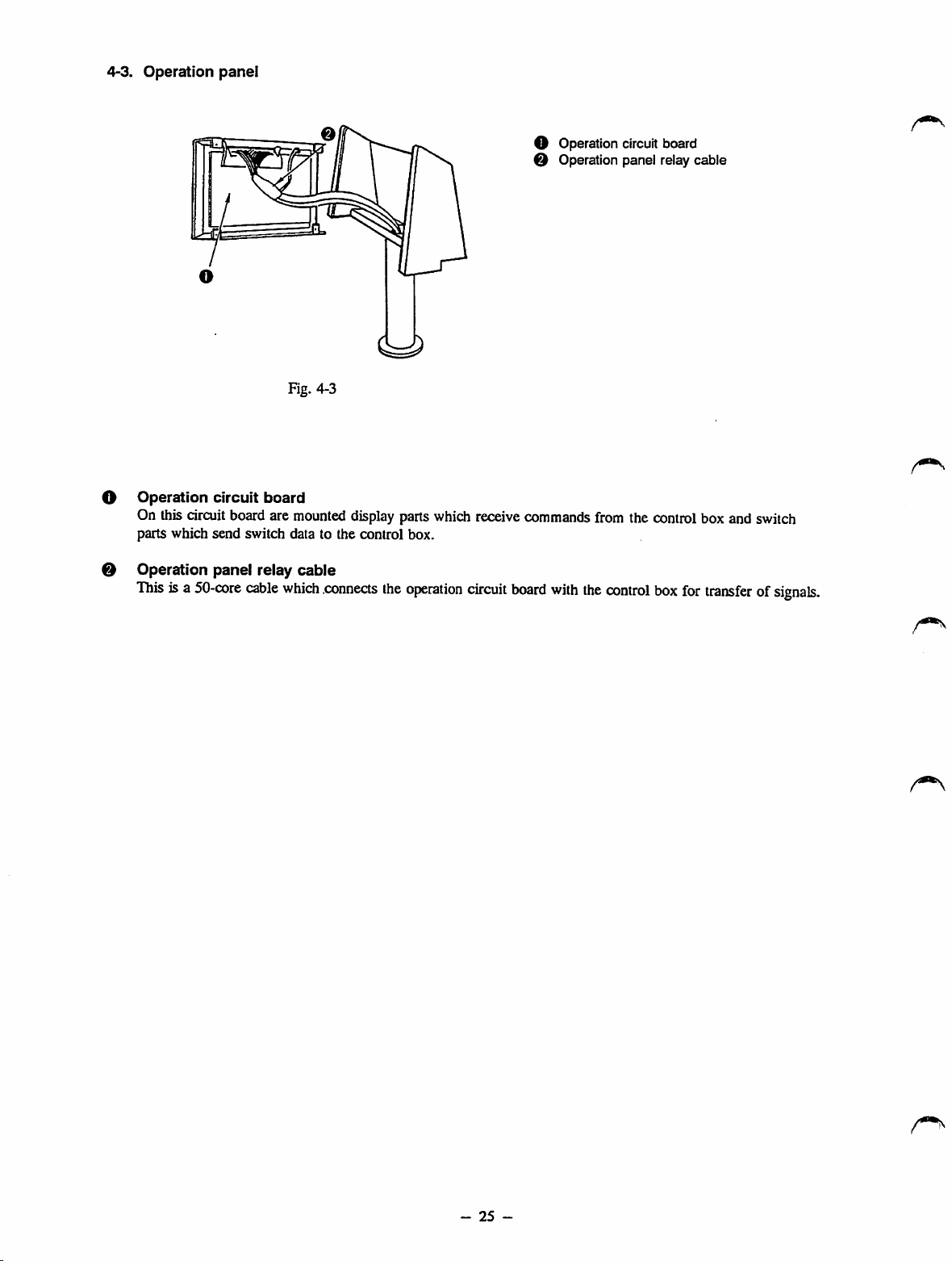
4-3.
Operation
panel
Fig. 4-3
O
Operation
On this circuitboard are
parts which send switch data to the control box.
0 Operation panel relay cable
This
isa
circuit
50-core
board
cable
mounted
which
.connects
O Operation
O Operation panel relay cable
displayparts which receive commands from the controlbox and switch
the
operation
circuit
board
with
the
circuit
control
board
box
for
transferofsignals.
-
25
-
Page 35

4-4.
Motor
A 400W, 4-pole electronic-slop motor is used for the sewing machine motor. The clutch brake disk components are
compatible with a general lockstitch sewing machine motor.
1. Structure of the motor and how the motor speed is changed
The following diagram shows the structure of the electronic-stop motor. As long as the power of the machine
stays ON, the motor (rotor, flywheel, and clutch disk) runs constantly. The clutch ring is connected to the output
shaft through the splines, so it rotates together with the output shaft, and can slide crosswise.
When the clutch coil is energized, lines of magnetic force are produced as shown by the solid line arrow, and the
clutch ring is pressed against the clutch disk, thereby transmitting the motor rotation to the output shaft. When
the brake coil is energized, lines of magnetic force are produced as shown by the broken line arrow, and the
brake ring is pressed against the brake disk (constructed integral with the pulley side bracket, and does not turn),
thus stopping the rotation of the output shaft.
At medium speed, the clutch coil and the brake coil are energized for a short period of time alternately for
rotation.
,—
^ ^
Brake
yoke
Pulley
side
bracket
End
cover
Clutch
Stator
\
„
Rotor
Intemal
Housing
bracket
yoke
X ^
Capacitor
machine)
Centrifugal fan
Fig. 4-4 Structure of Electronic-stop Motor
Clutch
/WWW/,
Clutch
disk
Brake
Clutch
Pulley cover
disk
shaft
-
26
-
Page 36

5.
ADJUSTMENTS
5-1.
Mechanical
parts
STANDARD
(1)
Checking
the
directionofrotationofthe
After confirming that the READY indicator
lamp has lit up, set the bobbin winder switch to
"ON", and press the start switch. At this time,
the handwheel should turn counterclockwise (in
the directionofthe arrow) as observed from the
pulley side.
reverse
and the
[Caution]
Be
suretocheck
the
handwheel
installedorthe
machine
Do
not
rotation
confirmed
If
direction,
madiine
has
been
start
sewing
of
the
as
correct.
the handwheel turns in the
error
willbeindicated,
wiU stop.
the
after
the
powers
completed.
unless
handwheel
direction
machine
supply
the
has
of
wiringofthe
direction
been
rotation
has
of
been
of
ADJUSTMENTS
handwheel
Fig. 5-1-1
ft&ADY
1 i
PdRernNa
XScato
YScato
Coiirter
Number
lln^
SMo»tm*iseM0
j 1
1
(2)
Heightofthe
needle
bar
Bringthe needlebar to the lowest dead point in its stroke. Adjust so that the
bar lower bushing is aligned with the upper marker line (for a DPx5 or
Marker
lines
the
DPx5
needle-
Marker
D
the
lines
DPx17
Fig. 5-2-1
for
needle
for
bottom
DPxl7
Fig. 5-2-2
end of the needle
needle).
Needle
lower
Upper marker line
V
Marker
the
(with
^of
bar
bushing
lines
for
DPx17
needle
needle
count
#22orhigher)
[Caution]
The
marker
lines
for
machineofwhich
DPx17 (#22orhigher
specification
code
G.
count)
are
only
engravedonthe
-
27
-
needle
barofthe
sewing
Page 37

oIfthe
motor
now
handwheel
power
turnsinthe
plug,
and
n
TO
ADJUST
reverse
direction,
reconnectitreversed.
0
Fig. 5-1-2
disconnect
the
RESULTS
o If
the
handwheel
direction,
the
error
switch
switchcan be operated.
OF IMPROPER
adjustment
the
machine
E.
In
canbeturned
turnsinthe
will
this
case,
OFF,
opposite
stop
showing
the
power
butnoother
1)
TurnONthe
up),
and
reaches
2^
Remove
3^
Loosen
^S
4)
After
5)
Turn
returntoits
6)
Attach
needle
threading
turn
the
handwheelbyhand
its
lowest
dead
rubber
plug0from
needle
bar
connection
o?
the
needlebyraisingorlowering
making
OFF
the
the
upper
rubber
adjustment,
needle
threading
resting
plug0to
switch
point.
the
setscrew0,and
securely
position.)
the
face
(the
until
face
p^te.
switch.
(The
plate.
the
needle
the
needle
needle
bar
adjust
me
bar
bar
O•
will
ill
o
Stitch
skippingorthread
occur.
breakage
may
-
28
-
Page 38

STANDARD
(3)
Stop
positionofthe
When the main shaft stops, marker dot O on the
machine arm should be midway between marker dot
No. 1 O and marker dot No. 2 on the handwheel.
For the sewing
G,
adjustsothat
machine
machine
arm rests between upper blue marker dot 0
main
shaft
of whichspecification code is
marker
dot O
engraved
and lower markerdot 0 engraved on the handwheel
when the sewing machinestops.
[Caution]
1. Be
suretodo
readytostart
2. This
adjustmentisunnecessary
operation.Ifthe
been adjusted, be
stop
position of
setonthe
this
sewing.
machine.
adjustment
stop
positionofthe
sure
the
main shaft with the workpiece
while
the
for normal
main
to check the newly adjusted
ADJUSTMENTS
on the
machine
shaft
is
has
Fig. 5-3-1
Direction
of
rotation
O
(4) Height of
1)
Make
and
up before setting the workpieceon the machine.
the
sure that the
the
sewing
Intermediate
sewing
pattern
indication
LED
presser
data has been
(READY
lamp)
2) Makesure that theneedleentry point is in the center
of intermediate presser
O-
3) Set Needle threading switch 0 in the control box to
the
4^
side.
The
feeding
presser
will
then
come
4) Turn the handwheel by hand until the needle bar
reaches
that
a 0.5
the
lowest
mm
dead
(standard
frame
down.
point
of its
adjustment
and
intermediate
stroke.
value)
Adjust
clearance
obtained between the top end of the intermediate
presser and the workpiece.
5)
After
making
the
adjustment,
set
Needle
threading
switch 0 to the side. The machinewill then
run
untilitreaches
maximum
the
intermediate
thicknessofthe
the
presser
needle-up
material
is 5
mm.)
stop
tobe
position.
sewn
read
has
(The
using
so
lit
is
Workpiece
Throat
Fig. 5-4-1
plate
-
29
-
Page 39

HOW
TO
ADJUST
RESULTS
ADJUSTMENT
OF
IMPROPER
Loosen
If the
solenoid
main
shaft
mounting
stops
prematurely
base
setscrew
before
O.
marker
dotNo.l O
or 0 on the handwheel reaches marker dot O on the machine
arm, move setscrew O in the direction of arrow (D and then
tighten the setscrew in that position. On the other hand, if the
main
shaftstops after
marker dotO,move setscrew O in the direction of arrow
and then tighten the setscrew in that position.
Repeat
3)
4)
step 1), 2)
located between marker dot No. 1 0 or 0 and marker dot No.
20
or 0 on the handwheel when the main shaft stops.
Securely
tighten
Directionofrotation
marker
until
solenoid
dot No. 2 0 or 0
marker
dot O on
mounting
the
machine
base
setsaew
Directionofrotation
passes
arm
O.
beyond
0,
is
If the main shaft stops before marker dot
O reaches marker dot No. 1 0 or 0
on
the
handwheel:
Thread trimming operation cannot be
completed (the main shaft stops before
the moving knife meets the counter
knife), leading to thread trimming
failure.
If the main shaft stops after marker dot
No. 2 0 or 0 passes
dot O on the machine arm:
A clearanceof1 mm or greater
beyond
marker
shown
in the figure cannot be obtained, and the
wiper and intermediate presser will come
in contact with the needle, which may
cause
the
needletobendorbreak.
The markerdot O on the
machine arm
marker
the
hcuidwheel.
dot
stopsatthe
No.2side
setscrew0,and
adjust
on
the
height
o
Loosen
The
msu'ker
machine
metrker
dot
the
handwheel.
intermediate
dot O on the
arm
stopsatthe
No.1side
on
presser
of the intermediate presser following the procedurestated on the
left. Uponcompletion of the adjustment,
tighten
the setsaew.
Be sure to adjust the height of the intermediate presser
according to the thickness of the material or the type
of thread to be used so that the material does not flap
during
sewing.
so that there is no clearance (0 mm),
o Afteradjusting the
check
the
position
ADJUSTMENTS (9).")
When
sewing
height
of the
of thewiper
floppy
material,
intermediate
adjust
presser,
be sure to
(Referto"STANDARD
1mmor
more
i
1mmormore
oIfthe clearance is too great:
Stitch skipping may occur,
oIfthe
clearanceistoo
Loose stitches may result.
small:
-
30
-
Page 40
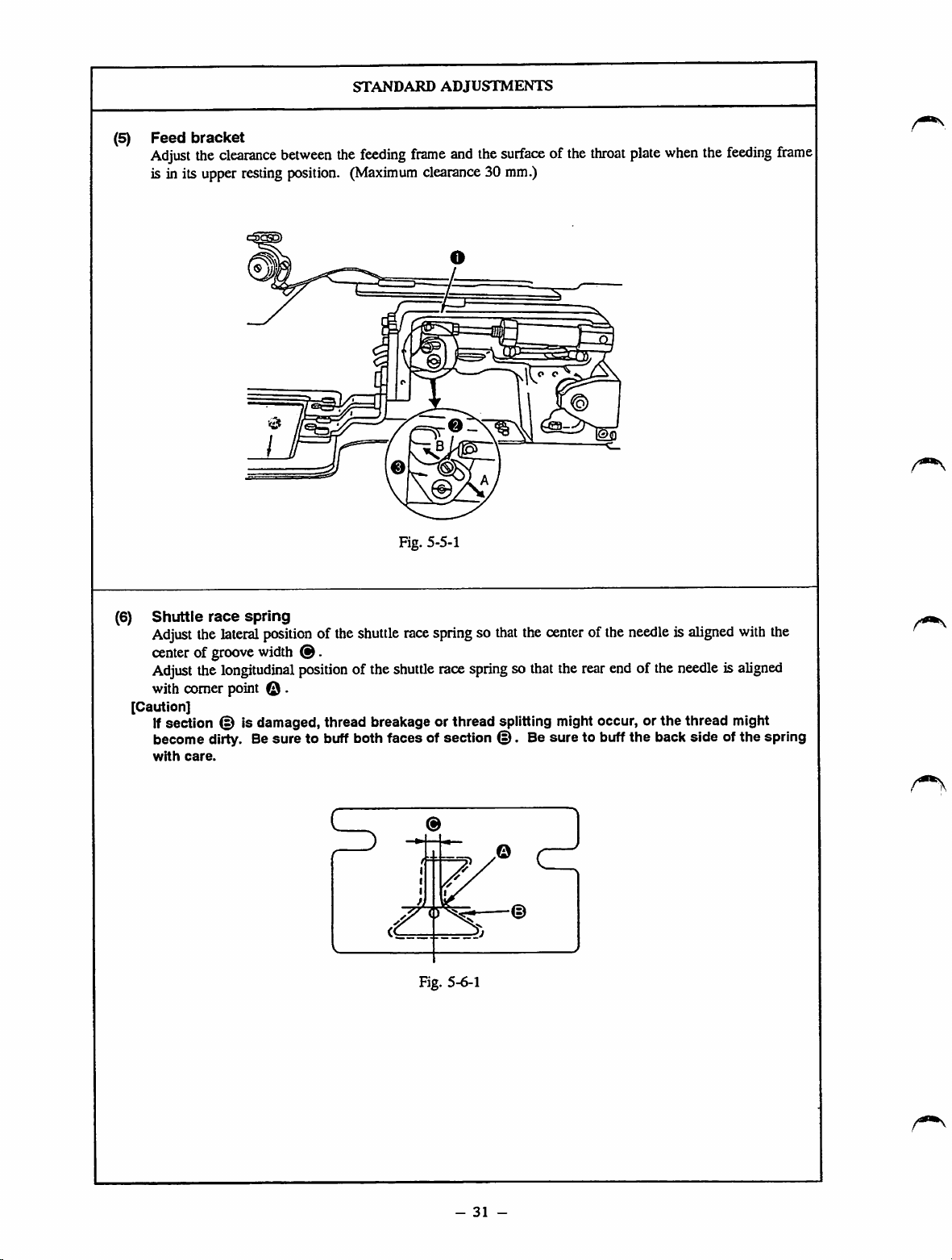
(5)
Feed
bracket
Adjust
the
clearance
is in its upper restingposition.
between
STANDARD
the
feeding
(Maximum
ADJUSTMENTS
frame
and
clearance30 mm.)
0
Fig. 5-5-1
the
surfaceofthe
throat
plate
when
the
feeding
frame
(6)
Shuttle
Adjust
centerofgroove
Adjust
with comer point © ,
[Caution]
Ifsection © is damaged, thread breakage or thread splitting might occur, or
become dirty. Besure to buffboth faces of section
with
race
the
the
care.
spring
lateral
position
width
longitudinal
of the
@.
position
shuttle
of the
race
shuttle
Fig. 5-6-1
springso
race
springsothat
that
the
center
the
©.
Be sure to buffthe backside ofthe spring
of the
rear
endofthe
needleisaligned
needleisaligned
the
thread might
with
the
-
31
-
Page 41

n
Loosen
sctcw0whichislocatedinthe
^ b
A
will
increase
din
2)
After
tighten
arrowBwill
the
adjustmentofthe
saew
now
TO ADJUST
®kcto.Shifting
the
heightoffeeding
decrease
lever®in
frame
.he
heigh,of.he
heightofthe
0.
right-handorleft-hand
the
dir^.on
O .
am>w|
^
feeding
frame,
securely
results
adjustment
o If
the
liftofthe
small;
The
material
o If
the
liftofthe
great:
The
correct
willbedifficult
material.
of
improper
feeding
cannotbeset
positioningofthe
feeding
when
frameistoo
easily,
firameistoo
you
trytoset
matenai
the|
o
Remove
adjus.
Ster"
completed.
ttie
feeding
.he
posWonofttie
positionofthe
the
standard
frame,
feed
pla.e
shuffte
race
shuttle
race
adjustmentofthe
0
Fig. 5-6-2
and
spring
usmg
^'"9f
shuttle
screw
race
has
U•
been
o
Lateralorlongitudinal
cause
the
needle
shuttle.
o If
the
shuttle
race
deeply,
the
moving
the needle thread,
o If
the
shuttle
not
race
hook
the
excessivelytothe
might
dislocation
threadtobite
springislocated
knife
springislocated
left,
bobbin
might
the
moving
thread.
into
will
not
the
too
hookj
knife
-
32
-
Page 42

(7)
Timing
between
the
needle
STANDARD
and
the
ADJUSTMENTS
shuttle
1) Needle bar timing
The bottom endofthe needle bar lower bushing is aligned with the lower marker line (for a DPx5 or
DPxl7
needle) when the needle goes up. (Fig. 5-7-1)
2) Shuttle timing
Under the condition described in step 1) above, the centerofthe needle meets the blade pointofthe
shuttle. (Fig. 5-7-2)
3) Clearance between the needle and the shuttle driver
Under the condition described in step 2) above, there will be no clearance between the needle and the
shuttle driver when the end face of the shuttle driver shaft is aligned with side © of the driver.
(Fig. 5-7-2, Fig. 5-7-3)
4) Clearance between the needle and the blade point of the shuttle
Under
the
condition
described
in step 2)
above,a0.05
to 0.1
mm
cle<irance
© will be
the needle and blade point of the shuttle. (Fig. 5-7-4)
5) Clearance between the needle and the shuttle race
The clearance between the side face of the needle and the shuttle race is a 7.5±0.2 mm (when a #14
DPx5 or
DPxl7
needle is used). (Fig. 5-7-5)
6) Clearance between the shuttle and shuttle driver
The clearance between the shuttle and the shuttle driver is 0.5 to 0.7 mm. (Fig. 5-7-2)
obtained
between
Marker
a
DPxS
Marker
a
DPx17
0.05to0.1
1) Needle bar timing
Needle
bar
lower bushing
lines
for
needle
lines
for
needle
Fig. 5-7-1
3)
4)
mm-«
Clearance
Clearance
the
JL/®
0
mm
blade
between
between
point of
the
the
shuttle
needle
\
needle
When a G type
is
used.
DPx17 (with
needle
count
if22 or higher)
Lower
Needle
and
the
shuttle
and
of
marker
bar
driver
Fig. 5-7-3
lines
Shuttle
2) Shuttle timing
Shuttle
driver
shaft
Shuttednver
d
Fig. 5-7-2
5)
Clearance
and
#14ofDPxSor—»
DPx17
needle
between
the
shuttle
the
race
7.5st0.2mm
needle
S
O 0
Fig. 5-7-4
-
33
-
Shuttle
Fig. 5-7-5
Page 43

now
TO
ADJUST
RESULTS
ADJUSTMENT
OF
IMPROPER
1)
Referto"STANDARD ADJUSTMENTS
(7)-!),"
and
that the lower marker line (for a DPx5 or DPxlT needle)is
aligned
2)
and
ADJUSTMENTS (7)-2)."
[Caution]
3)
adjusting
[Caution]
Loosen
the
with the
driver
longitudinal
bottom
faceof the
setscrewO,and
direction
needle
adjust
referringto"STANDARD
When adjusting the shuttle timing, be
in
the
directionofthe
Loosen
t.he
needle
if
the
needle
lower
shaft
and
bushing
® to
the
needs
arrowasshown
setscrew@.and
adjustsothat
front
endofthe
to be replaced according to a change in
there
shuttle
bar
lower
bushing.
the
directionofrotation
sure
to turn the shuttle
in Fig. 5-7-2.
turn
lower
bushing
is no
clearance
driver.
the type of needle, be sure to adjust the clearance between
the
needle
and
the
shuttle
be bent or damaged needles, be
timing after a needle
4)
Loosen
between
adjusting shaft
5)
between
shuttle
the needleand the blade pointof the shuttleby
Loosen
shuttle
the
Use
great
care
andthe blade
When
sewing
r^tcc
setscrewO,and
0.
race
setscrewO,and
needle
and
when
point
of the
withathin
driver.
has
been replaced.
the
shuttle
adjusting
shuttle
Since
sure
to check the shuttle
adjust
adjust
race.
the
clearance
described
typeofthread
there
are
the
clearance
the
clearance
between
instep 4).
such
bound
the
as#50
or a greater count, be sure to adjust the clearance so
that it is *7.0 to 7.3 mm after the standard adjustment
of the
position
completed.
[Caution]
of the
shuttle
racespring has
been
Strike portion (i) to adjust the clearance betweenthe shuttle
and
the
shuttle
After
making
positioned
driverto0.5to0.7mmas
the
adjustment,
equidistantly
besurethat
(clearance@and0should
shown
portion
in Fig. 5-7-2.
@ is
equal) and vertically with respect to the shuttle.
adjust
between
turning
needle
be
1), 2) Forsewing floppy material, adjust
so
the shuttle timing so that it is slightly
slower than the standard shuttle timing.
On the other hand, for sewing heavy
weight material, adjust the shuttle timing
so that it is slightly faster than the
standard timing (to prevent stitch
skipping.)
3) If
the
clearanceisgreater
the needlewill be bent by the blade I
point of the shuttle, resulting in scrtuchcs
on the blade point of the shuttle and the
needle.
has
to
driver, stitch skipping may occur.
4) If the clearance
On
excessive
the
contact
other
exceeds
hand,ifthe
with
range (0.05 to 0.1 mm), stitch skipping
may occur. If the clearance is
inadequate, the needle will bit the blade
point of the shuttle, causing scratches on
the needle and the blade pointofthe
shuttle.
thread to bread or split finely.
The
scratches may cause the
5) If theclearance is less than7.5 mm,
poorneedle threadspreading may
oftenleading to the needle thread biting
into
the
shuttle.
When sewing with a thinner
type of thread, such as #50 or
a greater count, adjust the
timing between the needle and
the
shuttle
racesothat
to 7.3 mm (the clearance
marked with an asterisk *).
Otherwise, the thread easily
bite
into
the
shuttle.
If
the
driver
clearance
and
the
between
shuttle
exceeds
specified range (0.5 to 0.7 mm), the
shuttle will produce loud noises. On the
other hand, if the clearance is
inadequate, the needlethreadwill fail to
smoothly leave the shuttle resulting in an
inadequately tensedstitch formation,
when sewing with a thick thread.
than0mm,
needle
the
shuttle
thespecified
result,
it is
7.0
the
shuttle
the
{
Fig. 5-7-6
-
34
-
Page 44

STANDARD
ADJUSTMENTS
(8) Heightofthe
The clearance A between the
intermediate
presser
bottom
adjusting
of the intermediate presseradjusting screw and the top of the
intermediate presser adjusting screw nut is 10±1 mm.
A:
Intermediate
adjusting
Intermediate
adjusting
screw
screw
presser
presser
nut
Fig. 5-8-1
(9)
Positionofthe
wiper
1) With the sewing machine stopped with its needle
up, confirm that the sewing indication LED
(READY lamp) light up, and set the Needle
Threading switch to the side. The clearance
between the wiper and the needle and between the
wiper and the intermediate presser should be 1 mm
or greater, when wiper O passes the tip of the
needle.
2) A 40 mm distance should be obtained between the
center of the needle and the end face of the wiper
O
when
[Caution]
Normally,
of
which
material
fall
to
the
Item 2ofFunction
switchto"1."
the
thread
wiper O
the
thickness
thickness
pass
wiper
under
under
returns
to its
canbeused
Is3mmorless.Ifthe
exceeds3mm,
the
needle.Inthis
No.45of
This
enables
the
the
Intermediate
home
position.
withamaterial
the
wiper
case,
the
memory
wipertospread
presser.
set
10il
will
screw
mm
1mmormore
m--"
1mmormore
40mm
35
-
Fig. 5-9-1
Page 45

o
Loosen
make
o
the
adjusting
the
adjustment.
Adjustable
Sige^©ofthe
is0to11for
isSor0to29mm
specification
HOW TO ADJUST
screw
After
the
sewing
machineofwhich
for
the
isHorG.
nut,
and
turn
the
making
intermediate
the
adjustment,
presser
adjusting
sewing
sewing
machineofwhich
secur
ly
screw
specification
sewing
results
o If
the
adjusting
tightened;
The
intermediate
up
upon
o If
the
adjusting
tightened:
A
functional
presser
[Caution] ^
This
adjustmentismadetoobtain
proper
presser.
directly
sewing
make
to
prevent
assembiy
of
adjustment
completionofa
mechanism
pressureofthe
relatedtothe
ability,
thisadjustment too
improper
screwisexcessively
presser
will
sewing
screwisinadequately
failureofthe
may
result.
intermediate
This
adjustmentisnot
machine's
itis
advisable
the
intermediate
from
becoming
failtogo
cycle,
intermediate
tnei
not
often
damaged.
to
so as
presser
i
1)
Loosen
procedure
2)
^
^nfag
wiper
arm
setsaew@.and
givenonthe
wiper
O is
left.
setscrew®so
appropriate.
make
the
After
Wipertothe
that
adjustment
making
the
adjustment,
centerofthe
the
angleofattachment
ntedle
[o
The
top
endofthe
contact
with
intermediate
thread
wiping.
hy
If
the
of
I brake or become bent,
o If
machineisoperated
keptincontact
intermediate
intermediate
the
tipofthe
tipofthe
the
needle
thread,
andastitdiing
wiper
may
come
the
needle
or the
presser
preventing
with
the
presser,
presser,orthe
the
needleisdamaged
proper
with
the
needleorthe
needle,
wiper
needleisburredorthe
may
stick
into
the
needle
failure
may
in
,
wiper
might
(the
like),
result.
-
36
-
Page 46

(10)
Lengthofthread
STANDARD
remainingonthe
ADJUSTMENTS
needle
The length of thread remaining on the needle after thread trimming is 35 to 40 mm measured from the
needle
eye.
For synthetic thread, the length of thread remaining on the needle should be increased.
Thread
tension
controller
Long
(D
Short
No.
1
©
Fig.
5-10-1
(11)
Thread
take-up
spring
Stroke: Pull the needle thread in direction©. Moving distance of the needle thread should be 12 to
15 mm from the start to the end position. (Fig. 5-11-2)
Tension:
Adjust
the
tension
according
to the
spring by checking the result of the
machine.)
Thread
tcd<e-up
spring
Smal
stitch
formation.
adjustment
When making a knot
(Adjust
the
tension
of the
by sewing the workpiece actually set on the
thread
take-up
L-shaped
thread
guide
Fig. 5-11-1
-
37
-
Fig. 5-11-2
Page 47

now
TO
ADJUST
RESULTS
ADJUSTMENT
OF
IMPROPER
Adjust tension controller No. 1.
o Turningit in direction © decreasethe length of thread
remaining on the needle,
o Turningit in direction © increases the
lengthofthread
remaining on the needle.
[Caution]
If
the
tension
trimming,
short.
The
thread
short,ifthe
Referto"RESULTSOFIMPROPER
release
the
thread
Referto"STANDARD ADJUSTMENTS (19)."
remainingonthe
thread
timingisdelayedatthe
remainingonthe
needle
may
take-up
spring
does
ADJUSTMENT
needle
alsobecut
not
work
timeofthread
willbecut
normally.
too
(11)."
oIfthe thread remaining on the needle is
too
short:
The thread may slip off the needle at the
sewing start,
oIfthe thread remaining on the needle is
too long:
The thread may appear on the right side
too
of
the material, or make the wrong side
of
the material look messy. The thread
may also bite into the shuttle at the
sewing start.
1) Adjusting the stroke
Loosen
No. 2
setsaew
0,
O >insert a screwdriver into tension controller
and turn it to adjust the stroke.
2) Adjusting the tension
Be sure that setscrew O has been securely tightened. Insert a
screwdriver into tension controller No.
20
, and turn it to adjust
the tension. (Fig. 5-11-1)
[Caution]
When sewing with a thinner thread
count, adjust the stroke of
is8to10mm.
the
such
as #50 or a greater
thread take-up spring so that it
If
the stroke exceeds the specified range:
The thread remaining on the needle wiU
be too short, resulting in the thread
slipping off the needle at the sewing
start.
If the stroke is inadequate:
Needle breakage may occur at the
sewing start when sewing with a thin
thread.
[Caution]
If
the
thread
take-up
contact
guide,
not
thread
with
the
the
thread
returntothe
trimming,
remainingonthe
In
this
case,
adjust
L-shaped
thread
in
take-up
contact
thread
with
guideatsection
care
nottodamage
(Fig. 5-11-2)
spring
L-shaped
take-up
start
position
and
the
needle
the
positionofthe
guidesothat
spring
does
the
L-shaped
B. At
this
the
thread
comes
thread
spring
thread
will be
not
thread
time,
in
will
before
short.
the
come
take
path.
-
38
-
Page 48

STANDARD
ADJUSTMENTS
(12)
1)
Thread
The
breakage
detector
thread breakage detecting disk should be
always in contact with the thread take-up spring
in
the
absence
of
thread
on
the
machine
(The slack of the thread take-up spring should
be about 0.5 mm.)
The thread breakage detecting disk should not
2)
be in contact with any other metallic parts
except the thread take-up spring.
[Caution]
Whenever
spring
breakage
(13) Moving knife
1)
When
portion
the
strokeofthe
has
been
detecting
the sewing
changed,
and
machine
disk
counter
thread
the
thread
mustbereadjusted.
knife
stopswith its
of the moving knife and the end of the needleeyelet is 4.5 mm for the S or H type machine, or 6
mm for the G type machine.
2) Theclearance
provided
between
the
type machine, or 1.5 mm for the G type machine.
head.
take-up
needle
counter
Thread
take-up
spring
Thread
breakage
detecting disk
Tension
up, the clearance
controller
provided
Kg.
No.
5-12-1
between
2
the loopspreading
knifeand the needle holeguide is 0.8 mm for the S or H
Excluding G
type
Fig. 5-13-1
G
type
%
-
39
-
Page 49

now
TO
ADJUST
results
adjustment
of
improper
at
left.
1) When
S
2)
'intme
3)
guideOand
After
adjustment,
ofmov®hnifeOand
adjustnient.
the
counter
Section
tobe
leferto p39
deleting
tighten
manuaUy
dis.
«.jus«nentasdescribed
the
setscrew.
actuate
the
between
knife
d •
adjusted
(13))
1)
the
edge
thread
o£
needie
trininter
the
to
needle
h^^^
2)
11Ifthe
thread
notinproper
take-up
2)Ifthe
o If
spring,
would
failtostop
|)ro<iks
thread
falselyincontact
other
than
sewing
even
when
the
counter
is
smaUer
The
the
blade
when
machine
clearance
threads
they
knife.Asa
bobbin
short.
o If
the
counter
is
larger
The
longer
fabric
trimmer
o If
the
counter
is
larger
The
result
failures.
o If
the
counter
is
smaller
The
The
endofthe
proper
hit
The
breakage
contact
the
even
breakage
withametallic
the
thread
would
it is
started.
provided
knife
and
than
the
maybefalsely
pointofthe
are
pulledbythe
result,
threads
wouldbetrimmed
clearance
knife
and
than
the
thread
after
thread
may
failtotrim
clearance
knife
and
than
the
unreliable
with
consequent
clearance
knife
and
than
thread
trimming
needle
thread
moving
stitch
the
moving
bobbin
runs
detecting
with
sewing
when
detecting
take-up
stop
the
needle
specified
disk
the
thread
machine
the
thread
disk
part
spnng,
immediately
between
hole
value:
tnmm^
counter
both
provided
the
specified
maybeleftonthe
trimming,
provided
the
specified
thread
provided
the
the
specified
maybecaughto"®
knife
formation.
knife
idling
knife
moving
the
needle
between
needle
hole
value:
the
the
threads,
between
needle
hole
value:
spreader
thread
between
needle
failures
preventing
Tht
and
may
excessively.
trimming
hole
value:
may
is
is
the
the
guide
by
and
too
. ^
the
guide
thread
the
guide
may
the
guide
result.
the
needle
may
brake.
-
40
-
Page 50

STANDARD
(14)
Heightofthe
o
The threadtrimmerwhich consistsof a movingknife and counter knife should successfully cut a pair of
moving
knife
and
the
ADJUSTMENTS
counter
knife
#80 thread and another pair of #5 thread when the throat plate is removedand the thread rimming lever
is manually actuated. (Fig. 5-13-1) (S, H type)
The
thread
trimmer
which
consists
of a
moving
knifeand
counter
knife
should
successfully cut a pair of
#2 thread and another pair of #30 thread. (G type)
Hinge
screw
Moving knife
Washer
Throat plate
Fig. 5-14-1
o Parallelism of the counter knifeblade point
The
counter
knife
blade
shouldbeparalleltothe
threads (needle and bobbin threads) evenly.
'TTTTZ^
Fig. 5-14-3
S, H type:
0.3to0.4mm
G type:
0.5to0.6mm
throat
Counter knife Moving knife
Needle hole guide
Fig. 5-14-2
plate
mounting
The counterknifebladeis
plate mounting surface. The difference in level
between © and @ is within 5/100.
surfaceinordertocutapair
paraUel
to the
throat
of
-
41
-
Page 51

now
TO
ADJUST
RESULTS
ADJUSTMENT
OF
IMPROPER
1) After the trial thread trimming.
A. If the outer thread as observed from the moving knife pivot
cannot be trimmed, replace the washer with a thicker one.
B. If the inner thread as observed from the moving knife pivot
cannot be trimmed, replace the washer with a thinner one.
Part
No.
B242328000A
B242328000B
B242328000C
B242328000D
Inner
Outer
Nameofpart
Moving knife washer
Moving knife washer
Moving knife washer
Moving knife washer
Thickness
0.4
mm
0.5
mm
0.6
mm
0.7
mm
Moving knife
Moving knife pivot
Fig. 5-14-4
o Thread trimming failures may occur.
If the above adjustment fails to correa the thread trimming
2)
failure.
A. If the height of the needle hole guide with respectto the counter
knife blade is not within 0.3 to 0.4 for S or H type model of
sewing
machineor0.5to0.6mmforGtype
(Fig.
5-14-2)
height
of the
out
usingascrewdriver
needle
holeguidewith
or the like to
respect
one,
to the
pry
portion
adjust
counter
O
the
knife
blade to the correct height. (At this time, make sure that the
bladepointis in
If the angle of the counterknife bladeillustrated belowis larger
B
parallel
to the
throat
plate
mounting
surface.)
than 90 degrees, cut the blade.
JCQJCSL
Tobeacute
angle
Fig. 5-14-5
3) If
the
corrective
measures
described
in1)
and2)above
fails
to
correctthe trouble, replacethe movingknife or the counter
knife.
o If the height of the needle hole guide
with respect to the counter knife blade
exceeds 0.4 mm(S, H type)0.6 mm (G
type), both the needle thread and the
bobbin
thread
willbecut
Esp)ecially
thread, the needle thread and bobbin
when sewing with a thin
too
short.
thread will be frequently cut too short.
-
42
-
Page 52
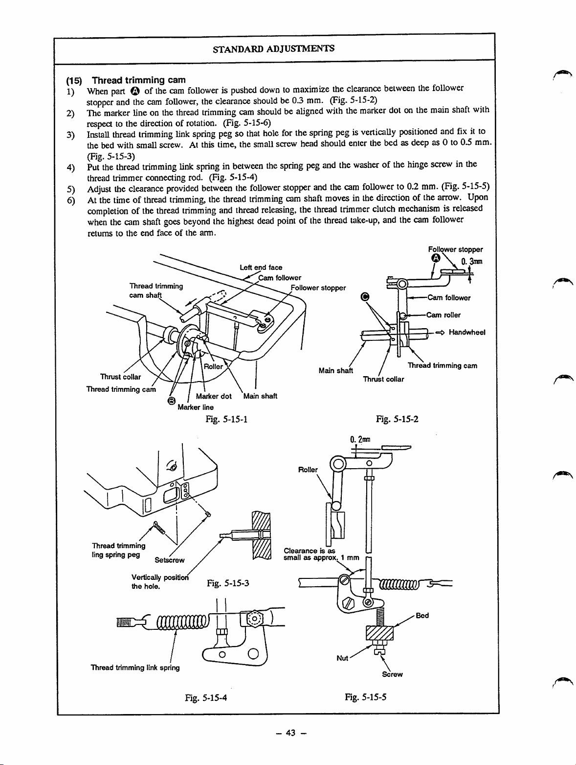
STANDARD
ADJUSTMENTS
Thread
(15)
When
1)
stopper
The
2)
respect
Install
3)
the
(Fig.
Put
4)
thread trimmer connecting rod. (Fig. 5-15-4)
Adjust
5)
At
6)
completionofthe
when
retumstothe
trimming
part
© of
and
the
marker
lineonthe
to the
thread
bed
with
5-15-3)
the
thread
the
clearance
the
timeofthread
the
cam
Thread
cam
cam
the
cam
followerispushed
cam
follower,
thread
directionofrotation.
trimming
small
trimming
link
spring
screw.Atthis
link
springinbetween
provided
trimming,
thread
trimming
shaft
goes
beyond
end
faceofthe
trimming
shaft
arm.
the
trimming
between
clearance
(Fig.
pegsothat
time,
the
the
thread
and
the
highest
downtomaximize
shouldbe0.3
cam
shouldbealigned
5-15-6)
hole
for
the
small
screw
the
spring
follower
trimming
thread
releasing,
dead
pointofthe
Left
end
face
Cam
follower
mm.
the
head
peg
stopper
cam
shaft
the
Follower
the
(Fig.
with
spring
pegisvertically
should
and
the
and
the
movesinthe
thread
trimmer
thread
stopper
clearance
5-15-2)
the
marker
enter
thebedas
washerofthe
cam
followerto0.2
directionofthe
clutch
take-up,
between
dotonthe
the
follower
main
positioned
deep
as 0 to 0.5
and
...
hinge
screwinthe
mm.
(Fig.
arrow.
mechanismisreleased
and
the
cam
follower
Follower
-Cam
follower
Cam
roller
shaft
fixitto
5-15-5)
Upon
stopper
0. 3n*n
Handwheel
with
mm.
Thrust
collar
Thread trimming
Thread
tnmming
ling
spring
peg
Vertically position
the
cam
ID
hole.
Marker
Roller
Marker
dot
line
Fig. 5-15-1
Fig. 5-15-3
Main
shaft
Main
Ro
er
Clearanceisas
smallasapprox.
shaft
1 mm
0
Thrust
Fig. 5-15-2
collar
Thread
trimming
cam
Thread trimming link spring
Fig. 5-15-4
-
43
-
Fig. 5-15-5
Page 53

HOW
TO
ADJUST
1)
Loosen
2)
Inserta0.3mmspacer
hook
follower so that the follower
follower
3)
Press
cam
4)
5)
6)
7)
[Caution] ^ ,
setscrewd)and
ofthe
cam
follower,
wiU
comeinclose
the
thread
trimming
follower
thrust collar onto the main shaft.
Align
marker
onto
the
againstthe thrust collar.
Install
spring
screw.Atthis
as deep as 0 to 0.5 mm.
Put
the
and
the
connecting
longer
the
hook
Placea0.2
the
cam
link
stopper
thread trimming link stopper.
Do
not
might
cam follower stopper and the cam follower.
roller
the
marker
doton the
main
shaft
thread
trimming
pegisvertically
time,
thread
trimming
washerofthe
rod.Atthis
hook
toward
downward.
mm
thick
follower
until
use
any
extremely
setscrew
between
and
cam
inthe
directionofthe
lineonthe
main
cam.
while
pressing
link
positioned
the
small
link
hinge
time,
the
thread
spacer
and
tighten
you
feelasmall
tool
when
reduce
the
@.
the
follower
puUupportion
stopper,
contact.
thread
spring
spacer,and the cam
and
the
thrust
trimming
Screw
the
thread
the
thread
pegsothat
and
fixitto
screw
head
handwheel.
springinbetween
screwinthe
face
trimming
between
the
screwinthe
tightening
clearance
thread
the
endofscrew
link
the
follower
load.
Now,
the
provided
stopper
© of the
collar
cam
trimming
trimming
the
bed
should
the
and
thread
fix
screw.
and
against
Screw
with
the
cam
hole
for
with
enter
the
spring
trimmer
that
the
opening
stopper
trimming
the
nutofthe
Usingatool
between
the
cam
the
cam
the
small
bed
peg
has
and
the
1)
2)
b)
the
|[Caution]
a
of
RESULTS
Thread
trimming
The
machine
start or thread trimming.
The
thread
tothe
start
a loose stitch formation for the first
stitch at the sewing start.
If
the
machine locks, be
the
play
to
the
shaft
phase of the thread trimming cam.
Also
check
OF
IMPROPER
ADJUSTMENT
failure
may
lockatthe
cam
shaft
will
positionintime,
ofthe
main
shaft
direction,
the
related
may
occur.
timeofthe
failtoreturn
resulting
suretocheck
with
respect
position
parts.
or
in
(Excluding Q type)
(
0
Marker
•
line
Marker
<!
dot
Fig. 5-15-6
(G type)
Marker line Marker
\_
/
-
44
dot
-
Page 54
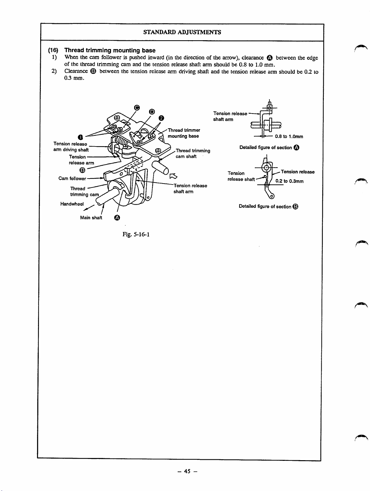
(16)
1)
Thread
When
trimming
the cam
mounting
followerispushed
STANDARD
base
inward
ADJUSTMENTS
(in the
direction
of the
arrow),
of the thread trimming cam and the tension release shaft arm should be 0.8 to 1.0 mm.
2)
Clearance©between
03
mm.
release
Tension
release
Cam
follower
Thread
trimming
Hctndwheel
o
shaft
arm
©
cam
Tension
arm driving
the
tension
release
arm
driving
Thread
mounting
Thread
cam
Tension
shaft
shaftand the
trimmer
base
trimming
shaft
release
arm
Tension
shaft
tension
release
arm
Tension
release
clearance©between
release
arm
should
•
E
0.8to1.0mm
[Detailed
Detailed
figureofsection
shaft
figureofsection
Tension
0.2to0.3mm
the edge
be0.2 to
©
release
©
Main
shaft
Fig. 5-16-1
-
45
-
Page 55

HOW
TO
ADJUST
RESULTS
ADJUSTMENT
OF
IMPROPER
1)
Loosen
setsaew
0.
Moveplate ® ,
which
retains
the
release shaft arm, forward or backward so that clearance ©
between the edge of the thread trimming cam and the tension
release shaft arm becomes 0.8 to 1.0 mm. After adjustmait,
securelytighten setscrew
2)
Loosen
setscrew
O • Move
©.
stopper@forwardorbackward
that clearance © between the tension release arm driving shaft
and
the
tension
adjustment,
release
securely
arm
tighten
becomes
setscrew
0.2to0.3
O •
mm.
After
tension
1) At the time of thread trimming, the top
endofthe
comeincontact
tension
with
release
the
shaft
end
faceofthe
thread trimming cam, and the thread
trimming cam shaft will not be able to
travel
the
normal
stroke
lock
amount.
will
occur.
trimming,
so
result, a
machine
2) Aftercompletion of thread
thread trimming cam shaft will fail to
return. As a result, a
occur.
machine
arm
will
As
a
the
lock will
-
46
-
Page 56
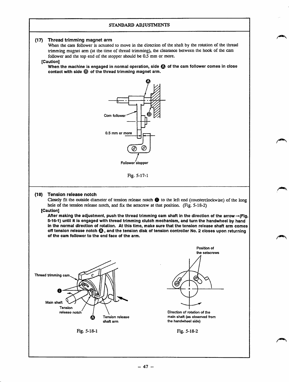
(17)
Thread
trimming
magnet
STANDARD
arm
ADJUSTMENTS
When the cam follower is actuated to move in the direction of the shaft by the rotation of the thread
trimming
magnet
arm (at the time of
thread
trimming),
theclearance
between
the hook of the cam
follower and the top end of the stopper should be 0.5 mm or more.
[Caution]
When
the
contact
machine is
with
side
(§) of
engaged
the
thread
in normal operation,
trimming magnet arm.
Com
follower
side
Q of
the
cam follower
comesinclose
0,5mmor
more
0 @
Follower
(18)
Tension
Closely
release
fit the
notch
outside
diameteroftension
hole of the tension release notch, and fix the setscrew at that position. (Fig. 5-18-2)
[Caution]
After making
5-16-1) until it is
in
the
normal
the
adjustment,
engaged
directionofrotation.Atthis
with
push
thread
the
offtension release notch o , and the tension disk of tension controller
of
the
cam
follower
to
the
end
faceofthe
stopper
Fig. 5-17-1
release
thread
trimming
time,
arm.
notch
trimming
clutch
make
O to the left end
cam
shaftinthe
mechanism,
sure
that
the
(counterclockwise)
direction of
and
turn
the
tension
release
No.
2 closes upon returning
Position
the
setscrews
of the long
the
arrow-»(Fig.
handwheelbyhand
shaft
arm
comes
of
Thread
trimming cam
Meun
shaft
Tension
release
notch
Fig. 5-18-1
Tension
shaft
arm
release
-
47
-
Directionofrotationofthe
main
shaft
the
handwheel side)
Fig. 5-18-2
(as
observed
from
Page 57

o
Appropriately
ttorad
is
obtained
the
follower
o
Refertothe
position
trimming
between
stopper.
"DISASSEMBLY/ASSEMBLY
(46)"onhowtomake
HOW
the
magnet
the
cam
the
TO
ADJUST
thread
trimming
aim
shaftsothat
toUower
adjustment.
magnet
the
specified
notch
and
the
PROCEDURES
armonthe
clearaiice
top
end
of
results
adjustment
o
Since
the
mechanismisnot
thread
be
rotatesathigh
damage,
the
Since
with
trimming
thread
trimming
performed
abrasion,
corresponding
the
cam
the
follower
mechanism
properly.Asa
will
occur.
of
improper
trimming
completely
and
even
speed.Asa
tension
when
clutch
release
the
result,
main
loosening,orplay
parts
may
occur.
follower
comesincontact
stopper,
will
the
not
result,amachine
released,
will
shaft
in
thread
work
lock
o
Loosen
setscrewO.and
refetringtothe
making
the
adjust
the
"STANDARD
adjustment,besuretosecurely
ADJUSTMENTS
tighten
(18).
After
setscrew
O
o
The
lengthofthread
needle
after
thread
short and inconsistent,
o
The
thread
may
eyeat the
sewing
remainingonthe
trimming
slip
out
from
start.
wiU
the
be too
needle
-
48
-
Page 58

(19)
Amountofreleaseofthe
Pressing the
thread
the normaldirection of
STANDARD
tension
trimming cam shaft in the direction of the arrow
rotation
until the tension releaseshaft arm rests on stepped
ADJUSTMENTS
disks
(-»•),
turn the handwheel by hand in
portion
tension release notch. Now, the rising amount of the tension disk of the tension controller No. 2 should
be 0.6 to 0.8mmfor S or H type
modelofsewing
machine
or 0.8 to 1.0mm for G
type.
Fig. 5-19-1, Fig. 5-19-2)
Increase
S, H type:
0.6to0.8mm
G type:
0.8to1.0mm
© of the
(Fig.
5-16-1,
Fig. 5-19-1
Fig. 5-19-2
-
49
-
Page 59

now
TO
ADJUST
RESULTS
ADJUSTMENT
OF
IMPROPER
o Loosenthread
of releaseof the
referring to the
[Caution]
o After making
check
thread
are completeiy ciosed. (The tension disks
highest
o if
the
tension
actuating
the
desired pattern to actuate
that
the
take-up
dead
the
tension
arm setscrewO , and adjust the
tension
"STANDARD
the
adjustment,
thread
tension
reaches
point.)
disks
cioseatthe
machine, be
disks by moving
ADJUSTMENTS
turn
the
disks
keep
Hs highest
sure
dead
timeofneedle
to open
the
thread trimming, or by
thread
tension
(19)."
handwheei by hand to
opening
point
and
openatthe
threading
the
disks by sewing
pressing the thread trimming cam shaft in the direction of
arrow (Fig. 5-16-1)to turn
directionofrotation
mechanism workingsothat
upper
resting
position.
and
the
handwheei in
start
the
the
the
normai
thread
trimming
main shaft is brought to
amount
untii
the
ciutch
arm0
the
disks
or
the
the
The length of thread remaining on the
needle after thread trimming will be too
short
and
inconsistent.
A loose stitch formation may result.
-
50
-
Page 60

(20)
Intermediate
STANDARD
presser
ADJUSTMENTS
(Theadjustments should be madeafter the operation air pressure has been decreased to 0 kgf/cm^)
1) After confirming that the READY lamp lights up, turn the Needle Threading switch ON and OFF several
times, and check that the intermediate presser moves smoothly up and down.
o The clearance between the intermediate presser adjusting screw and the nutofintermediate presser
adjusting screw should be 10±1 mm for S type model of sewing machine or 5±1 mm for H or G type one.
(Fig. 5-20-1)
o The intermediate presser rod should projects 19±0.2 mm (dimension B) from the top end of the
intermediate presser bracket for S type model of sewing machine, or 2±0.2 mm for H or G type one.
o The needle should enter the center of the hole in the intermediate presser. (Fig. 5-20-3)
b Hie air
flow
adjustmentofspeed
controller
(B)
mounted
onthe
intermediate
presser
cylinder
has
been
appropriately made. (Refer to the "STANDARD ADJUSTMENTS (41).")
The operating air pressure has been adjusted to 5 to 5.5
kgf/cm"
using the air regulator. (Refer to the
"STANDARD ADJUSTMENTS (41).")
2) The marker dot on the main shaft is alignedwith the marker line on the intermediate pressercam. (Fig. 5-
20-4)
3) The clearance between the end face of the intermediate presser aim and the end face of the intermediate
presserrod is 1 mm with respect to the direction of the arrow after play has been
eii.minated.
(Fig.5-20-5)
4) When the intermediate presser is in the lowest position of its stroke, the clearance between the bottom
face of the intermediate presser and the top face of the intermediate presser bar lower bushing is 3±0.2
mm.
Additionally,
positioning
pinOkeepsincontact
withthe top end of
positioning
link 0 whilethe
intermediate presser is actuated. (Fig. 5-20-5, Fig. 5-20-7)
[Caution]
After making
been
done
the
adjustment,
properly.
turn
the
handwheei by
hand,
and
make
sure
that
the
adjustments
has
intermediate
adjusting
Intermediate
adjusting
screw
presser
screw
presser ^
nut
Fig.
Marker
5-20-1
Intermediate
presser
dot
Marker
Fig. 5-20-4
Intermediate
presser
cam
line
bracket
Fig.
Intermediate
presser
intermediate
presser
¥
5-20-2
1
mm
rod
Fig. 5-20-5
Face
bar
intermediate
plate
Fig. 5-20-3
side
Needle
Intermediate
presser
lower
bushing
rV
bar
Fig. 5-20-6
Intermediate
presser
Intermediate
presser
bracket
bar
-
51
-
Page 61

n
Adjustsothat
adjusting
is
o
Loosen
adjust
from
screw
10±1
mm. (Fig.
intermediate
the
the
top
intermediate
modelofsewing
(Fig.
5-20-3)
the
holeinthe
presser
bracket
2)
Loosen
intermediate
adjustment
2)."
Then
sewing
machine,
intermediate
main
shaftintermsofthe
type
one,
shaftintermsofthe
At
the
the
marker
the
lowest
needle
Move
intermediate
its
stroke
lowest
lineindirection©,and
reach
needle
Uming
materialtobe
(Fig. 5-20-4)
3)
When
making
intermediate
ITcWo
4)
Loosen
(Fm
setscrewOwith
5-21-1),
"STANDARD
presser
oscillating
link0closely
HOW
TO
ADJUST
the
clearance
and
5-20-1)
endofthe
between
the
intermediate
presser
bracket
presser
rodsothatitprojects
intermediate
the
intermediate
presser
clamping
presser
machine,or2±0.2mmforHorGtype
and
that
the
needle
point
enters
intermediate
clamping
referringtothe
tighten
setsaew0.ForSorHtype
align
presser
align
the
marker
timeofdeUvery,
line
and
positionofits
bar
reaches
the
marker
presser
earlier
position.Onthe
the
lowest
bar.Bymaking
presser.
screwO.(Fig.
presser
cam
"STANDARD
the
marker
cam
with
normal
line
reverse
the
the
intermediate
Now,
5-20-3)
setscrew
ADJUSTNffi^
line
engravedonthe
the
marker
dot
directionofrotation.
with
the
marker
directionofrotation.
marker
dotisaligned
presser
strokeatthe
the
lowest
positionofits
lineindirectionQ,and
will
reach
the
lowest
than
the
needle
bar
will
other
hand,
move
the
intermediate
positionofits
stroke
this
adjustment,
canbeobtainedinaccordance
sewn.
the
adjustment
presser
cam
the
"^ANDARD
and
make
ADJUSTMENTS
shaft0with
pressed
describedinstep
and
the
end
the
needle
the
adjustment
(20)-4)"bymoving
intermediate
against
positioning
0
face
ADJUSmEmS
baratits
describedinthe
presser
adjusting
screwO,Md
19±0.2
bracket
tighten
©'
forStype
just
the
intermediate
center
model
engravedonthe
dotonthe
reaches
time
when
stroke.
the
position
reach
its
the
marker
presser
later
than
the
the
optimum
with
the
type
2),
adjust
intermediate
lowesteapx)i
pinQ.(fig-
1)
screw
nut
[Caution]
mm
one
ot
(20-
of
For
U
mam
with
the
of
will
of
presser
(20).3),
intermediate
results
The
intermediate
up
after
cycle.
Refer
tothe
ADJUSTMENT (8)."
o The
intermediate
up
after
cycle.
top
endofthe
may
enter
lower
bushing
presser
The
needle
of the holeof the
Asaresult,aloose
occur,orthe
with the intermediate presser.
2)Ifthe
3)
4)
[Caution]
timing
presser
its
strokeismuch
whenthe
dead
pointofits
may
occur.
Onthe
the
intermediate
lowest
timing
lowest
stitches
intermediate
the
overlapping
The
intermediate
pushed
rod
and
whenthemainshaft
•normal direction.
Abnormal
machine operation.
Abnormal
especially
positioning
adequately
positioning
kepttooperateinthis
corresponding
The
obtained.
adjustments
of
improper
adjustment
presser
the
completion
-RESULTSOFIMPROPER
presser
the
completion
The
round
cornered
intermediate
the
intermediate
while
the
goes
up,
resultinginan
may
failto
intermediate
stitch
needle
will
when
the
reaches
the
lowest
earlier
needle
bar
stroke,
other
hand,
if the
presser
dead
pointismuch
when
the
needle
dead
pointofits
maybefonned
presser
sectionsofthe
presser
against
specified
the
theload
torque
noise
may
noise
will
when
Intermediate
link0does
comeincontact
pinO.If
parts
vertical
(Refertothe
intermediate
may
failtogo
ofa
sewing
may
fail
togo
ofa
sewing
sectioninthe
presser
presser
bar
intermediate
oil
enter
the
center
presser.
formation
comeincontactj
intermediate
dead
point
than
the
timing
reaches
(21).")
the
lowest
stitch
skipping
timing
when
reaches
bar
stroke,
or the
maybecaught
rotates
occur
be produced
might
stroke
the
later
than
reaches
loose
material.
cam
may
presser
may
fluctuate
in the
during
presser
not
with
the
machine
condition,
break.
will
"STANDARD
bar
leak.
wiU
of
the
the
in
be
the
not
|
is
be
Fig. 5-20-7
-
52
-
Page 62

STANDARD
ADJUSTMENTS
(21) Vertical
1) The center of connectingshaft nut O of the intermediate presser rod aligns with marker dot
At this time, the vertical stroke of the intermediate presser is 4 mm (at the time of delivery).
If the
connecting shaft nut O of the intermediate presser rod should be positioned as shown in the table below,
or aligned
Furthest point in direction
Marker dot Q
Marker
Furthest point in direction ©
[Caution]
If
Be
wiper has become improperly positioned, be sure to readjust its position. (Fig.
2) If the
lowest position):
Connecting
0.5mmclearance
dead pointofthe needle bar. (Fig. 5-21-2)
3) If the vertical stroke of the intermediate presser is set to return from 0 mm to 3 to 7 mm:
Referto the
strokeofthe
the
sure
vertical
vertical
vertical
stroke
with
the marker dot.
Alignment point
dot
strokeofthe
to checkthe position of the wiper (refer to the
stroke
shaft
nut
"STANDARD
of the
of the
O of
between
intermediate
intermediate
Verticalstroke of the intermediate presser (mm)
(fi)
intermediate
intermediate
the
intermediate
intermediate
ADJUSTMENTS
presser
presser
presser
presser
varies
within
7
6
5
3
presserischanged:
"STANDARD
is set to 0
presser
positioning
(20)-4)."
mm
rod
shouldbefixedinthe
link0and
the
range
(the
from
3 to 7
ADJUSTMENTS
intermediate
positioning
mm,
the
(9)").Ifthe
5-21-1)
presserisfixed
lowest
position
pin
© in the
®.
center
in the
providing
highest
of
a
Fig. 5-21-1
m
(D
Fig. 5-21-2
-
53
-
Page 63

HOW
TO
ADJUST
RESULTS
ADJUSTMENT
OF
IMPROPER
1)
Loosen
connecting
shaft nut O of the
intermediate
presser
and moveintermediate presser rod O in the direction of arrow
to
inaease
arrow
the intermediate presser is 4 mm.
Use
marker
to
decrease
dots
the
stroke.
the
©,
© and @ as the
Move
stroke.
the
The
rodinthe
standard
standard
direction
vertical
of
stroke
pointstomake
the adjustment. A 6 mm stroke is obtained when the center of
the connecting shaft nut of the intermediate presserrod aligns
with marker dot
©.
A 5 mm stroke is obtained when the
center of the connecting shaft nut of the intermediate presser rod
aligns with marker dot
©.
A 4 mm stroke is obtained when the
center of the connecting shaft nut of the intermediate presser rod
aligns with marker dot
©.
2) Fix connectingshaft nut O of the intermediatepresser rod in
the lowest position.
Bring the needle bar to its highest dead point.
Loosen
shaft 0 so that a 0.5 mm clearance is obtained between
intermediate presserpositioning link 0 and
Securely
[Caution]
3) Refer to the
setsaew
O >and move intermediate presser oscillating
positioning
tighten
setsaew
Make
sure that Intermediate presser positioning link 0 does
not come in contact with positioning pin
intermediate
contact
handwheelisturnedbyhand
machine
against
spring, breakage of
5-21-1,
presser
with intermediate
operates
the
pin
and
Fig.
5-21-2)
"STANDARD
O.
O,
and the
oscillating shaft 0
presser
to rotate
under
the
condition
the
oscillating
the
corresponding parts may result. (Fig.
ADJUSTMENTS
does
not
spring0,when
the
main shaft. If
that
the
shaft
hits
against
(20)-4)."
link
pin
come
the
hits
the
1) The specified vertical stroke of the
rod
intermediate presserwill not be o^ained.
In
ordertooverride
of
overlapping section of the
material,
the
vertical stroke
the intermediate presser should
be made greater. In this case,
be
suretoremember
floppy material cannot be
easily fedifthe vertical stroke
is too great, resulting in stitch
skipping.
2) The 0 mm vertical stroke of the
intermediate presser will not be obtained
0.
in
the
3) Referto the
ADJUSTMENTS (20)-4)."
"STANDARD
the
of
that
-
54
-
Page 64

(22)
The
The
thed5 holein the
its lowest position.
At
intermediate
distance
the
time,
the
presser
from
the
intermediate
intermediate
center
^5
hole
STANDARD
lifting
of the d5
stroke
ADJUSTMENTS
holeinintermediate
presser
cylinder
cylinder0shouldbe130.5±0.2mmwhen
presser
lifting
stroke
issetto20mm(at
^5
hole
Fig. 5-22-1
knuckle
the
intermediate
the
timeofdelivery).
O to the
cylinder
center
(Fig.
of
is in
5-22-1)
(23)
Bobbin
The
bobbin
Holder
winding
holder
boss
should
release the
Top
cover
Fig. 5-23-1
bobbin
Bobbin
holder
when
the
bobbin
has been
wound
Fig. 5-23-2
80%
full.
Winding
cam
-
55
-
Page 65

o
Loosen
adjust
referringtothe
shaft
the
making
cylinder
the
knuckleO•(Fig-
now
nut@of
screwing
"STANDARD
intermediate
depthofthe
adjustment,
TO
ADJUST
presser
intermediate
ADJUSTMENT
securely
tighten
5-22-1)
cylinderO,and
cylinder
(22)."
nutOand
o
knuckle
After
O
intermediate
RESULTS OF IMPROPER
adjustment
When
the
mm;
The
intermediate
less
than20mm.
When
mm:
The
intermediate
lifted.
top
endofthe
may
enter
lower
presser
distance
the
distanceisless
The
the
bushing
goes
exceeds
presser
presser
round
cornered
intermediate
intermediate
while
the
up,
resultinginan
130.5±0.2
lifting
stroke
than
130.5±0.2
will
fail
tobe
section
in the
presser
bar
presser
bar
intermediate
oil
leak.
is
1)
Loosen
so
that
wound
2)Ifthe
rearofthe
After
the
bobbin
the
bobbin
80%
full.
above
adjustment
top
making
holder
holder
After
cover,
and
the
adjustment,
boss
nut.
releases
making
does
the
not
adjust
tighten
Turn
the
the
bobbin
adjustment,
work,
loosen
the
angleofthe
setscrew
bobbin
holder
which
has
been
tightent^nut.
setscrewffat
bobbin
holder.
O-
boss
t e
oAnimproper
wound on the bobbin.
amountofthread
will
be
-
56
-
Page 66

(24)
Bobbin
driving
Bobbin
winder
wheel
winder
Main
driving
shaft
wheel
Face
STANDARD
plate
side
ADJUSTMENTS
552:0.4mm
Bobbin winder driving
z
wheel
irnr
Arm
]
Fig. 5-24-1
(25) Height of
0.3
mmor
en
the
Throat
less
throat
Throat
plate
@
plate auxiliary
plate auxiliary
cover
cover
Fig. 5-24-2
Auxiliary
supports
cover
(right)
Auxiliary
cover
-
Fig. 5-25-2
57
-
Fig. 5-25-1
Page 67
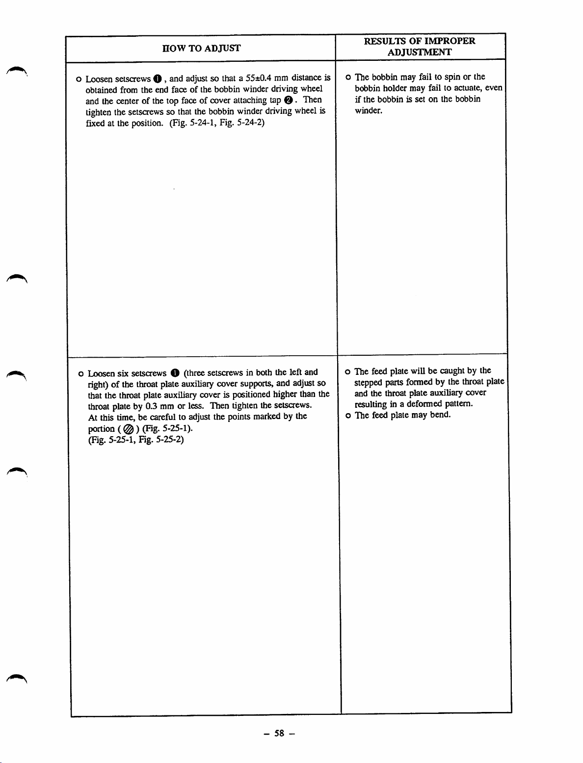
now
TO
ADJUST
RESULTS
ADJUSTMENT
OF
IMPROPER
o
Loosen
obtained from the end face of the bobbin winder driving wheel
and
setscrews O »snd
the
center
tighten
the
of thetop
setsaews so
adjust
so thata
faceofcover
that
the
bobbin
55±0.4
attaching
winder
mm
tap
O.
driving
distance
fixedat the position. (Fig.5-24-1,Fig. 5-24-2)
Then
wheel
o The bobbin may fail to spin or the
is
is
bobbin holder may fail to actuate, even
if
the
bobbinissetonthe
winder.
bobbin
Loosensix setscrews O (threesetscrewsin both the left and
right)
of the
throat
plate
auxiliary
thatthe
throat
At this time, be carefulto adjust the points
portion(@)
throat
plateauxiliary coveris
plateby 0.3 mm or less. Then
(Fig.
5-25-1).
cover
supports,
positioned
tighten
thesetscrews.
marked
and
adjust
higherthan the
by the
(Fig.5-25-1,Fig. 5-25-2)
so
The feed plate will be caughtby the
stepped
and the throat plate auxiliary cover
resulting in a deformed pattern.
The feed plate may bend.
parts
formed
by the
throat
plate
-
58
-
Page 68

STANDARD
ADJUSTMENTS
(26) Heightofthe
work
clamp
foot
slider
Presser plate
Work
clampfoot slider
/ /
3.5»0.2mm
Feed
bracket
O
Fig. 5-26-1
(27) Holding
used)
forceofthe
feeding
frame
ball
The feeding frame support shaft is released from the feeding frame ball catcher when the feeding frame
support
shaft
baseispressed
in the
direction
of the
•y/
catcher
arrow
Feeding
ball
catcher
Work
(when
frame
clamp
with
foot
slider
the
optional
3.5 to 4.0
base
feeding
kgf/cm^
frame
load.
(Fig.
arm
5-27-1)
is
Feeding
frame
support
shaft
base
Feeding
frame
support
shaft
(28)
Vertical
The distance from the center of the 65 holeofthe work clamp foot cylinder knuckle to the centerofthe
65 holeofthe cylinder knuckle should be 120.5±0.3 mm, then the shaftofthe work clamp foot cylinder
is in its lowest position. (Fig. 5-28-1)
strokeofthe
work
clamp
Fig.
5-27-1
foot
Holding
adjusting
IgO.&sO.Smm
force
screwO
D
Cylinder
knuckle
Hose
elbow
Fig. 5-28-1
-
59
-
Page 69

o
Loosen
is
slider
wrench.
setscrew
obtained
between
basebyturning
Then
HOW
O >
tighten
TO
ADJUST
^nd
adjustsothata3.5±0.2mmclearance
the
presser
plate
and
the
work
clamp
the
work
clamp
foot
slider
base
setsaew
O.
foot
using
o The
RESULTS
pattern
OF
IMPROPER
adjustment
maybedeformed.
a
o
Refertothe
holding
force
Turn
holding
direction,
adjust
mounted
Loosen
screwing
referringtothe
After
using
each on the left and right.
"STANDARD
forceofthe
adjusting
holding
the
screw
force
force
willbeincreased.
and
the
holding
one each on both the rightand leftside.
nut
O of
depthofthe
"STANDARD
adjustment,besuretosecurely
nut
O*
Equally
ADJUSTMENT
feeding
O-
adjusting
holding
force
forceofthe
the
work
cylinder
adjust
(27),"
frame
ball
catcher
saewOclockwise,
Turn
the
using
and
screwinthe
willbedeaeased.Besure
two
feeding
clamp
cylinder
knuckle
ADJUSTMENTS
the
two
frame
shaft
with
regardtothe
fix
the
cylinder
cylinders
ball
and
(28).
mounted
and
adjust
holding
the
catchers
adjust
knuckle
the
reverse
to
the
shaft
one
oIfthe holding force is too strong:
The
feeding
removed.
o If the holdingforceis inadequate:
When
sewing
The
If
the distance exceeds 120.5±0.3 mm:
The feedingframe may fail to go up as
high as 30 mm.
If the distance is less than 120.5±03
mm:
The
down
As a
the
held securely.
frame
the
feeding
end,
the
pattern
maybedeformed.
feeding
to the
result,
correct
position
cannotbeinstalled
frame
goesup at the
feeding
framemayfail to come
lowest
theworkpiece
frame
position of its stroke
may
sinceit
may
may
slip
or
drop
from
notbe
-
60
-
Page 70
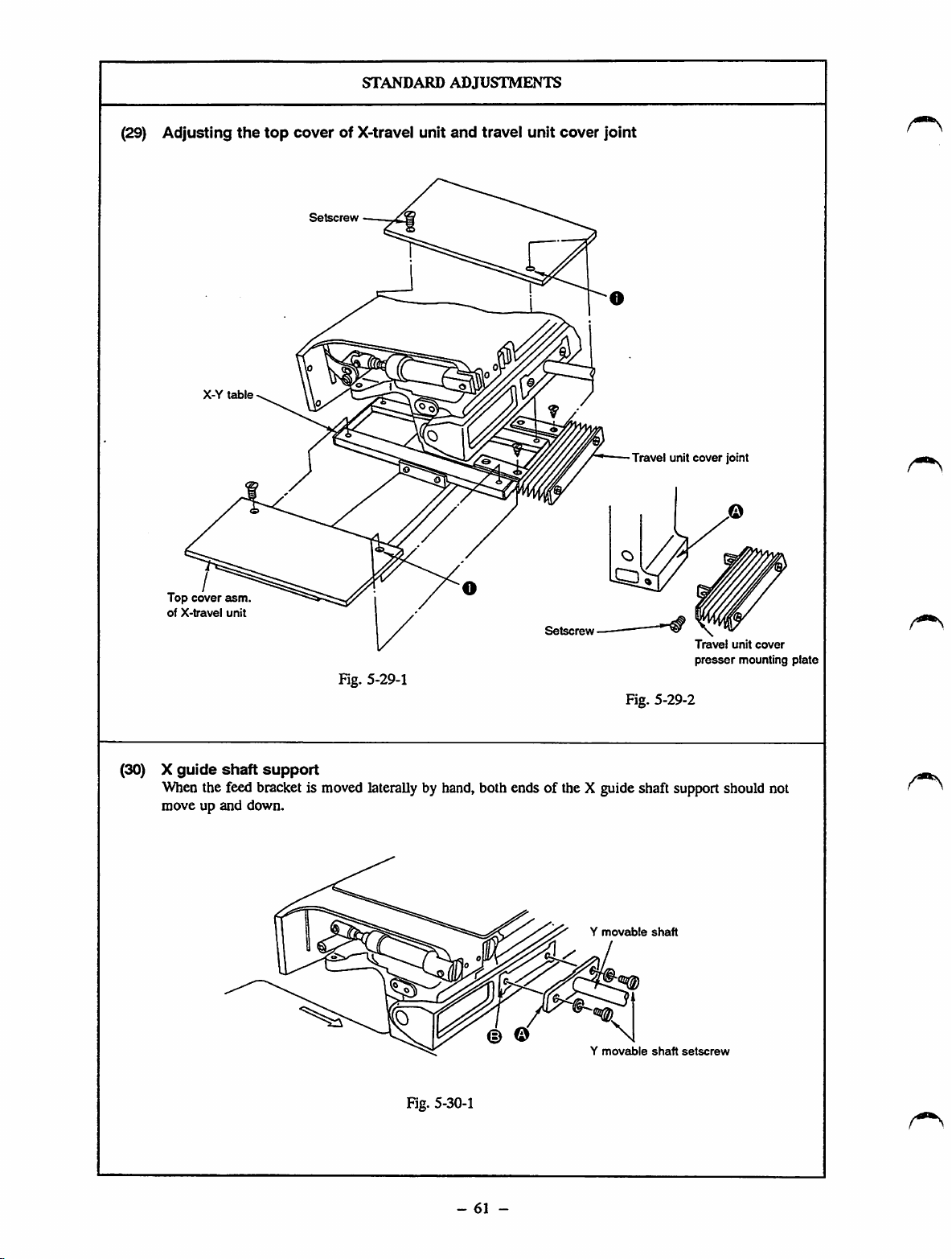
(29)
Adjusting
X-Y
table
the
top
cover
of X-travel unit
STANDARD
ADJUSTMENTS
and
travel
unit
cover
joint
Top
of
cover
X-travel
Travel unit
asm.
unit
cover
Travel
presser
Fig. 5-29-1
Fig. 5-29-2
(30) X
guide
shaft
support
When the feed bracket is moved laterally by hand, both ends of the X guide shaft support should not
move up and down.
joint
unit
mounting
cover
plate
© © \
Fig. 5-30-1
-
61
-
Y
Y
movable
movable
shaft
shaft
setscrew
Page 71

now
TO
ADJUST
RESULTS
ADJUSTMENT
OF
IMPROPER
o Put the top cover asm. of the X-travel unit between the X-Y
table and the travel unit cover joint and fit the bored portion on
the rearof the
travel
unitcoverjoint to
drilled
hole
O.
o Fix the top cover of the X-travel unit using the setscrews. Two
of
these setscrews are commonly used to fix the travel unit cover
joint.
[Caution]
After
the
wellasto
not
pushed
auxiliary
-29-2
and
adjustment,
the
right
against
cover
-53-1)
and
move
and
lefttoconfirm
feed
bracket
the
travel
the
feed
auxiliary
unit
bracket
cover
that
cover,
(A).
back
the
(Figures
top
and
cover
throat
forth
plate
5-29-1,
o Closely fitting the travel cover presser against plane A, fix the
travel cover presser mounting presser on the feed bracket with
the setscrews. (Figures 5-29-1 and -2)
o The corresponding parts may become
damaged.
as
Is
Move the feed bracket toward the handwheel (in the direction of
the arrow) by hand until it will go no further.
Loosen
theYmovable
shaft
setscrews so that
sideAof
the Y
movable shaft comes in full contact with side B of the X guide
shaftsupport. Then
tighten
theY
movable
shaft
-
setscrews.
62
-
o The pattern may be deformed.
Page 72

(31)
X-direction
Move
the
feed
feed
bracket
STANDARD
belt
tension
as far to the left as
ADJUSTMENTS
possible.
Adjustsothat
the
X-direction
feed
1.6to 1.8 mm when a load of 500 g is applied to the middle (shown by the arrow) of the right belt.
1.
6~1.
Sirni
belt
slackens
by
(32) Y motor
y
movable
shaft
mounting
base
Fig. 5-31-1
Y motor mounting
base
(asm.)
Y motor mounting
(asm.)
setscrews O
SS7151210SP
- 4
base
PCS.
Fig. 5-32-1
-
63
-
Page 73
now
TO
ADJUST
RESULTS
ADJUSTMENT
OF
IMPROPER
o
Loosen
to
[Caution]
Tightening
screwOand
adjust
the
belt
screwOwili
beltslackagainaftertightening screwO •
nut
tension.
0 •
Turn
Tighten
affect
the
tension
adjusting
saewOand
belt
tension,socheck
(Fig-
nut
0 .
5-31-1)
screw
0
the
o Thepattern may be deformed.
(1)
Move
the
Y-travel
which
the
moving
(2)
Adjust
the
heightoftheYmotor
torqueof2.5to4kgis
shaftispressed,inthe
directionofthe
[Caution] * .t. i
1.Donot
2.
Adjust
3.
This
connect
machine.
theY
adjustment
maintenance. So, never loosen the screw In the Y motor
base
(asm.).
shaft
back
and
forth
torqueismaximizedisreached.
basesothatastarting
developed
aforementioned
arrow
the
connectorofthe
motor
base
is notnecessaryinthe
with
the
when
state
stepping
presser
untilaposition
pressing
(1),inthe
motor
plate
regular
the
Y-travel
removed.
at
tothe|
A loud noise will be produced along
with the feed in the Y-direaion. The
pattern
maybedeformed,
I
corresponding
damaged.
partsmay
orthe
become
-
64
-
Page 74

STANDARD
ADJUSTMENTS
(33)-1
A. Adjusting the origins
1) Remove the needle.
2) Set the origin gauge within the feeding frame.
3)
4) Turn ON the powerswitch, and press the feeding frame switch to let the feedingframe come down. Then
5)
6)
B.
1)
2)
3)
4)
Fine
adjustmentofthe
Remove
cover
the scale. (Fig. 5-33-2)
attach
Press
found, the feed
[Caution]
Afterthe origin has been found, the feeding frame
come down only when the feeding frame switch is depressed. (Notethat
in contact with the needle ifthe feeding frame goes up with
the feeding frame to its highest position after the needle
travel limit, first remove
Turn
the
[Caution]
five
setscrews0,loosen
O.
Set
rotary
the
needle.
the
start
switch.
the
handwheelbyhand
needle
pointispositioned
DIP
mechanism
Oncethe originadjustment has been completed, turn
switch
Adjusting the X/Y travel limit
Follow
Press
the
shown.) (Fig.5-33-1, Fig. 5-33-3)
Move the needle point back to within the X travel limit.
Press
that
be shown.) (Fig. 5-33-1, Fig. 5-33-3)
O to 0
the
jog
needle
jog
the
procedure
keys!
point
keys
needle
(the
switch
described
4-<
[and!6^[on
stops
onthe X
I8a
|and|2yjon
point
stopsontheYtravel
XA^
origins
the
switch
O on
Only
the
feed
will be stopped.
the
needle beforehand.)
until
the
above
has been
in step 1)
the
travel
the
three
the
mechanism
needle
the01
drilled
factory
through
operation
limit
of the
operation
limit
setscrews
I/F
circuit
@ of
control
board
mountedonthe
willbeactuatedtofind
will
not go up. The feeding frame will go up and
the
has
been removed. Before adjusting
bar
reaches
the
holefor the
OFF
lowest
origin
the power switch, and
- set to 0)on the scale.
5) of A.
paneltomove
origin
paneltomove
ofthe
gauge.
origin
the
feeding
(±1.5
the
feeding
gauge.
needle attached. Be sure to bring
box
cover
the
position
of the
(Fig.
frametothe
mm)
frame
(±1.5
Q >snd
right
origin.
the
of its
origin
remove
side
from
When
origin gauge will come
stroke.Atthis
gauge.
set
rotary
5-33-2}
rightorleftsothat
(Error
indication
forward
mm)
(Error
and
indication
control
you
to5 on
the
origin
the
time,
DIP
O willbe
backward
[4]
is
so
will
X/Y
Feeding frame
Feed
bracket
X
travel
Fig. 5-33-1
limit *2
drilled
for origin gauge
hole
Y
travel
limit
Y
X
travel
*3
travel
limit
limit
*1
*4
-
65
-
Page 75

now
TO
ADJUST
DOOOO
RESULTS
ADJUSTMENT
OF
IMPROPER
The
positions of the
X/Y origin
X/Y
sensor
on
operation
illustrated in Fig.
5-33-3.
travel
willbeshown
the
display of the
and
limit
panel
the
eis
X-dlrectlon
D:
Travel
E: Origin
F;
Travel
Fig. 5-33-2
limit
*2
limit
*1
Fig.
BO.
n
5-33-3
••ipsn
Y-directlon
G;
Travel
H; Origin
I:
Travel
IB
limit
•JUKI
nsQ
limit
*4
*3
AMS
8 -9
-
66
-
Page 76

STANDARD
ADJUSTMENTS
(33)-2 X/Y
origins
and
travel
limit
sensors
1) Remove the needle.
Remove setscrews O the feeding frame arm.
2)
Attach the sensor adjusting gauge taking the position of the feeding frame arm guide pin as reference.
3)
(The related dimensions for the sensor adjusting gauge are shown in Fig. 5-33-5.)
Check the positions of origin and the XfY travel limit referring to the "STANDARD ADJUSTMENTS
4)
(33)-l Fine adjustment of the X/Y origin". (See Fig. 5-33-5)
Work
clamp
Feeding
frame
Sensor
adjusting
gauge
Fig. 5-33-4
-
67
-
Page 77

now
TO
ADJUST
RESULTS
adjustment
OF
IMPROPER
A.
Adjusting
1)
Remove
feed
2)
Make
"STANDARD
3)
Press
move
drilled
4)
Loosen
the
from1to0.Immediately
setscrews
5)
Press
framesothat
travel
6)
Loosen
attaching
the
display
33-6) , ^ ..
7)
Press
framesothat
travellimit *2. (Fig.5-33-3)
8)
Loosen
attaching
the
display
the
X-axis
the
feed
bracket
cover.
the
adjustments
ADJUSTMENT
jog
kevsiTTi.rsrj,'
the
feeding
hole
for
originofthe
setscrewsO,and
leftorright
jog
limit
untU
O •
(Fig-
keyIsV|on
the
*1.
(Fig.
setscrews0»and
plate
asm.tothe
travel
limit*1changes
has
changed,
jog
keyl
4-<
the
setscrewsO»and
plate
asm.tothe
travel
limit*2changes
has
changed,
origin
and
bracket
auxiliary
describedinsteps
SAjand
frame.
Align
origin
moveXsensor
display
(B)
after
5-33-3,
Fig.
the
operation
needle
point
5-33-6,
move
leftorright
from1to0.Immediately
tighten
setscrewsO-(Fig-
|on
the
operation
needle
point
move
leftorright
from1to0.Immediately
tighten
travel
limit
covers
(33)-l, A."
|2t
|on
the
needle
gauge.
showing
the
display
5-33-5)
paneltomove
aligns
with
Fig.
5-33-3)
X-axis
until
paneltomove
aligns
with
X-axis
setscrews
O•
sensor
(left
and
1),3)and4)of
the
operation
point
with
(Fig.
5-33-5)
attaching
theXorigin
has
changed,
marker
right
travel
display
marker
left
travel
until
display
right),
and
the
panel
the
<60.5
plate
asm.
changes
tighten
the
feeding
line
Vof
limit
sensor
(F)
showing
after
5-33-3,
the
line
limit
(D)
Fig.
leeomg
Vof
sensor
showing
after
o If the
o If the travel limit has not been properly
to
to
[Caution!
the
origin
hasnot
adjusted:
The
origin
for
align
with
the
pattern.
adjusted:
The
sewing
area
stepping
the
reached. As a result, an abnormal noise
may be produced.
If
condition
mechanism
become damaged. Never operate the
machine until
have
motor
medianical
the
machine Is
been
mentioned
completed.
been
inputtingapattern
origin
for
maybenarrower.
failstostop
travel limit has been
operated
above,
components
the
proper
5-
the
properly
sewing
the
even
under
the
might
adjustments
fails
The
when
the
feed
toj
^^\fter^making
disk
enters
photo-couplers
the
sensor
slit
disk
7)
If
theydonot,
the
photo-coupler
disk
and
overlapping
the
adjustments,
the
center
and
photo-couplerby5
passes
through
adjust
the
photo-coupler."
depth
make
ofthe
the
the
the
clearance
clearance
sift
disk
mmormore,
three
Note
that
referringto"C.
simultaneously
sure
that
between
overlaps
when
X-axIs
sensors.
between
Clearance
that
you
with
step
the
X-axis
thesensor
the
top
the
(Fig.
the
slit
disk
between
should
adjust
4),6)and
slit
end
of
X-^is
5-33
and
the
slit
8)
the
-
68
-
Page 78

STANDARD
ADJUSTMENTS
5) Adjust the sensor adjusting gauge to obtain the following dimensions.
Marker
travel
line
limit
Marker
travel
/
^0.5
for
*1
58
Marker
travel
drilled
the
for
line
limit *41
limit
origin i
X-axis
for
hole
line
Y-axis
for
*3
58
/
Y-axis
136
Marker
travel
limit
line
for
X-axis
*2
8.5
d7
46
d4
dS
cnT
A.
foi
cn
in
ID
b
1
d4
Fig. 5-33-5
-
69
-
Page 79

HOW
TO
ADJUST
B. Adjusting the Y-axis origin and travel limit
9) Remove the Y sensor cover. (Fig. 5-33-8)
Follow the same procedure described in steps 2) and 3).
10)
Loosen setscrews O > move the Y sensor attaching plate
11)
to the left or right until display (H) showing the Y origin
changes from 1 to 0. Immediately after the display has
changed,tighten setscrewsO • (Fig. 5-33-3,Fig.
Press
jog
12)
keyQon
the
operation
paneltomove
feeding frame until display (I) showing the travel limit *3
changes from 1 to 0. Immediately after the display has
changed, stop the feeding frame. (Fig. 5-33-3)
Make sure that a gap between the sensor and the needle tip is
13)
1.5
mmorlessintermsofthe
•3.
With regard to display (G) showing travel limit *4, press jog
14)
marker
lineVof
key and make the adjustment referring to the procedure
described in step 12).
With regard to marker line V of travel limit *4, make sure
15)
that the specified distance is obtained referring the procedure
described in step 13).
[Caution]
After making
disk
enters
photo-couplers
the
sensor
slit
disk
not,
adjust
coupler referring to
the
photo-coupler.'
the
adjustments, make
the
centerofthe
and
photo-coupler
passes
the
through
clearance
clearance
that
the
slit disk overlaps
by 5 mm or
the
two Y-axIs
between
"0.
Clearance between
sure
that
between
more,
sensors.Ifthey
the
slit disk
the
the
when
and
the
5-33-9)
the
travel
Y-axis slit
the
sensor
top
the
the
slit disk
limit
end of
Y-axis
do
photo-
and
RESULTS
ADJUSTMENT
OF
IMPROPER
-
70
-
Page 80

X-eixis right
travel
limit
/
EE
sensor
-O-
TT
X-axis
X-axis
siadisk
\ ^
I • I
—===
P
bo
Fig. 5-33-6
STANDARD
X-axis
sensor
\ X-origin
3
-o-
ADJUSTMENTS
attaching plate
Vr-rA
sensor
o o
o o
^ \
!-axis
X"3
trav
travel
left
limit
sensor
—
TTTT
Y-origin
X-axis
sensors
E
7
X-8ucis
Fig. 5-33-7
n-TT
slit
disk
Y-axis
limit
'I
sensor
\
M.
travel
C.
Adjusting
Y-etxis
sensor
the
cover
Fig. 5-33-8
clearance
I I
between
®
theslit diskand the
Sensor
/
Y-origin
sensors
u-
Y-axis
attaching plate
photo-coupler
sensor
L_58±0.
Fig. 5-33-9
Y-axis
s It
Y-ongin
2irm_J
disk
Slit
disk
Y-axis
travel
limit
sensor
Fig. 5-33-10
-
71
-
Fig. 5-33-11
Y slit fixing
plate
Page 81

now
o
Adjusting
Respectively
tot
leftby92
5-33-10 and -11)
°
If?heYsm
r^,^ormorcfloosen
After
Adiust
Adjusting
Y
theX
they
work
mm.
the
adjustment,
theYorigin
the
travel
limit
sensor
position
when
the
Tlien,
plate
and
using
origin
sensor.
TO ADJUST
theXtravel
feeding
fix
them
photo-coupler
s^ws@and
fixitwith
sensors
frame
with
the
(ngh)
movestothe
screwsO.(Figures
do
not
overlapasdeep
adjust
theYslit
screws.
screws0.(Figures
automaticaUy
determines
^ ^
iigW
fnttng
5-33-9
and
the
positionofthe
and
^5
plate.
-11)
RESULTS OF IMPROPER
adjustment
o
The
sensors
or
travel
problems
adjustmentofthe
o
Since
with
corresponding
broken or damaged.
failtodetect
limits,
causedbythe
theslit
disk
the
photo-coupler,
resulting
originortravel
parts
the
in thesame
improper
may
comeincontact
the
could
become
X/Y
origin
limits,
j
""'Ssure
photo-coupler.
that
theamdisk
does
not
comeincontaet
with
the
-
72
-
Page 82

(34)
(35)
STANDARD
Shuttle
If
or
race
ring
the blade point of the shuttle becomes badly worn out, remove the shuttle race ring and check whether
not
the
hatched
section
illustrated
has
ADJUSTMENTS
the
dimensions
of
0.2
x 8
mm.
Binm
0.2™i
Fig. 5-34-1
Eliminating
play
from
the
main
shaft
Screwdriver
Thrust
Main
shaft
Bushing
4
' ' Thrustcollar Thread
collar
Handwheel
trimming
cam
Fig. 5-35-1
(36)
Belt
tension
The middle of the belt should slacken by 10 mm when section A of the belt is subjected to 1 kg load.
Fig. 5-36-1
-
73
-
Page 83

HOW
TO
ADJUST
RESULTS
ADJUSTMENT
OF
IMPROPER
oIfthe
hatched
section
does
not
have
the
dimensionsof0.2
8 mm, correct it using an oilstone.
o
Drawing
the
handwheel
in the
direction
of the
arrow,
fix the
thrust collar while pressing it against the intermediatebushing.
mmx
o Loosen nutsO,and move the motor up or down to change the
installation position of the motor.
[Caution]
Be
suretoremove
presser
removed.
or
Install
the
belt
with
the
Intermediate
o The vibrationofthe belt may increase,
resulting in the sewing machine
vibrating more greatly.
[Caution]
If
the
belt
become
the
sewing
-
74
-
the
vibrationofthe
belt
may
cover.
damaged.
belt
tension
machine.
beltIsexcessive,
comeIncontact
Asaresult,
before
the
Be
suretocheck
operating
belt
with
the
may
the
Page 84
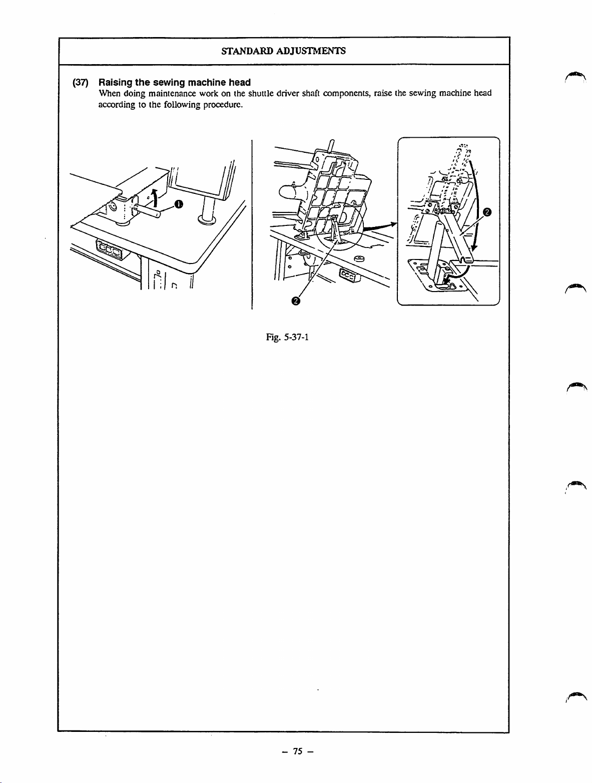
(37)
Raising
the
sewing
machine
STANDARD
head
ADJUSTMENTS
When doing maintenance work on the shuttle driver shaft components, raise the sewing machine head
according to the following procedure.
Fig. 5-37-1
-
75
-
Page 85

now
TO
ADJUST
RESULTS
adjustment
OF
IMPROPER
oToraise
sewing
the
Be
machine
^
Make^sure
dangerousIfthe
the
machine
arrow.
suretouse
raised.
sewing
machine,
and
raise
stopper©when
that
stopper©is
stopperisnot
attach
the
sewing
working
securely
gripOsupplied
machineinthe
with
the
locked.Itwillbevery
locked
properly
with
direction
sewing
the
of
-
76
-
Page 86

(38)
Removing
the
V-belt
STANDARD
Fig.
ADJUSTMENTS
5-38-1
Fig. 5-38-2
Fig. 5-38-3
77
-
Page 87

1)
Remove
2)
Attach
it in
stopper
3)
Remove
screwOand
grip 0
the
directionofthe
O.
(Fig.
V-belt
now
supplied
5-38-2)
©.
(Fig.
TO
ADJUST
remove
belt
with the
arrow.Atthis
machineinposition,
5-38-3)
cover0.(Fig.
time,besuretouse
5-38-1)
andraise
RESULTS
ADJUSTMENT
OF
IMPROPER
-
78
-
Page 88
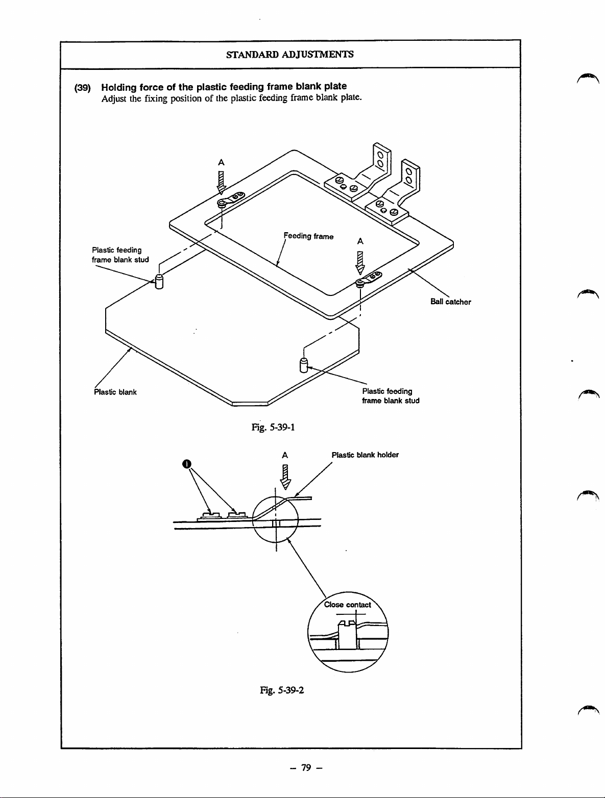
STANDARD
ADJUSTMENTS
(39) Holding force of
Adjust
the
fixing
Plastic
feeding
frame
blank
stud
the
plastic feeding frame blank plate
position
of the plastic
feeding
Feeding frame
frameblank
plate.
Ball
catcher
Plastic
blank
Fig. 5-39-1
Plastic
Close
blank
contact
Plastic
frame
feeding
blank
holder
stud
F5g.
5-39-2
-
79
-
Page 89
1)
Loosen
and
2)
Adjust
plastic
plastic
feeding
(Fig.
saewO•Attach
fixitproperly,
the
positionofthe
feeding
5-39-2)
feeding
frame
blankinthe
frame
frame
HOW
TO
ADJUST
the
plastic
(Fig.
5-39-1,
plastic
blank
comesinclose
blank
stud,
directionA.Then
blanktothe
Fig.
5-39-2)
feeding
while
frame
pressing
feeding
blanksothat
contact
the
tighten
with
the
plastic
screws
frame
the
O•
RESULTSOFIMPROPER
adjustment
o
The
plastic
feeding
easily
drop
from
the
plastic
feeding
be set to the feeding frame
frame
frame
feeding
blank
blank
frame.
may
may
fail
The
to
-
80
-
Page 90

(40)
Feed
plate
STANDARD
ADJUSTMENTS
0
Positioning
pin
Feed
plate
(Feed plate for inverting: B2556215A00)
B2556215000
©
Fig. 5-40-1
0 Setscrew (2 pcs.)
Washer
(2 PCS.)
SM6060802TP
WP0611626SP
-
81
-
Page 91
now
TO
ADJUST
RESULTS
ADJUSTMENT
OF
IMPROPER
1) Fit positioning pinO ^
feed plate with twoscrews0 . This
the feed plate.
determines
the position of
If you want to change the position of the feed plate, use the feed
plate with positioning pin O removed.
o The workpiece may slip duringsewing.
-
82
-
Page 92

STANDARD
ADJUSTMENTS
Adjusting
(41)
Connect
1)
indicate 5 to 5.5
If the value indicated on air pressure gauge O is lower than 4 kgf/cm" (0.4 MPa), error indication
2)
the
pneumatic
components
quick-coupling jointO , and openair cock0 . At this time, air pressure gauge 0 should
kgf/cm^
(0.5 to 0.55 MPa). (Fig. 5041-1)
will be given, and the machine will stop. (Fig. 5-41-1)
The air pressure on the work clamp cylinder retracting side has been reduced to 1 to 1.5 kgf/cm" (0.1 to
3)
0.15 MPa) and the feeding frame can be lowered by hand. (Fig. 5-41-2)
The needle knob of speed controller (for controlling the work clamp cylinder) is fixed by the nut at the
4)
position where the knob is turned in the reverse direaion by one revolution after it has been securely
tightened. (Fig. 5-41-3)
The needle knob of speed controller (for controlling the intermediate prcsser cylinder) is fixed by the nut
5)
at the position where the knob is turned in the reverse direction by five revolutions after it has been
securely lightened. (Fig. 5-41-4)
o
j
N'umbeq
IInput
UoM
^
1 Function
0 0 o
For controlling
clamp
cylinder (left)
the
work
1~1.5kgf/cia 0
For
Fig. 5-41-1
Fig. 5-41-2
controlling
cylinder (right)
the
work
Solenoid
valves (asm.)
Intermediate
cylinder (asm.)
presser
-
83
-
Page 93

HOW
TO
ADJUST
1)
Connect
and fix it withcableclip
2)
Connect
O of thejoint.
3)
Open
©byturningitso
5.5
the pressure value.
4)Ifthe
running
*
The
push
[Caution]
After
that it indicates 5 to 5.5
sure
5)
Under
©of
valve asm. Connect a commercially available pressure gauge.
(Fig. 5-41-2)
Treadle
needle
pressure
(0.1to0.15
©,
41-2)
6)
Adjust
"STANDARD
using
7)
Remove
the
air
female
air
cock©,pullitup
kgf/cm"
(0.5to035
compressed
while
indicating
air
pressure
the
button
making
that error indication
the
the
sewing
pressure
the
feeding
knob
© of
gauge
MPa).
and
connect
needle
nut
©.
the face
Adjust
needle
"STANDARD
using
nut
©.
supply
hosetoquick-coupling
®.
side
O of
the
quick-coupling
and
that
the
air
pressure
MPa).
Then
air
pressureistoo
error0on
willbe0
© .
adjustment,
mode,
reducing
kgf/cm"ifyou
set airpressure
kgf/cm®
{Aj
goes
remove
valveOthatisfixedonthe
frame
switch
pressure
reducing
then
adjust
press
low,
the
(0.5
out.
the
air
five
valve©,and
joint
jointtomale
air
gauge©indicates5to
the
the
machine
panel.
close
to 0.55
MPa),
hosebypressing
timesormore.
connectedsothatitindicjites1to
Then
fix
the
the
air
hose
which
knob©of
ADJUSTMENTS
(Fig.
plate.
knob©of
ADJUSTMENTS
(Fig.
speed
5-41-3)
speed
5-41-4)
knobatthat
has
controller©,referringtothe
(41)-4)."
controller©,referringtothe
(41)-4)."
position
been
removed.
Thenfix the
Then
(female)
adjusting
Jcnobtomaintain
air
cock©and
gauge
1.5
fix
side
knob
will
stop
© so
and make
section
solenoid
Then
adjust
the
kgf/cm
using
(Fig.
knob
the
knob
O
turn
nut
5-
RESULTSOFIMPROPER
ADJUSTMENT
1)
The
work
clamp
mechanism
intermediate
malfunction.
The
machine
showing
12)
The
machine
the pressure of the air source.
The
machine
showing
pressure
operating
(0.5 to 0.55
13)
The
appropriate
work
14)
The
come
may
insufficient speed.
15)
The
move
maybeproduced
presseris actuated.
I
[Caution]
Itis unnecessary to carry out Steps 2)
through to 5) in the
ADJUSTMENTS
machineisengagedinnormal
Note
describedinsteps3)through
coated
show
properly adjusted.
When
presser
mechanism
will stop runningwhile
error
indication
may
failtodetectadrop
will stop
error
indication
gauge
indicates
air
pressure
MPa)).
pressing
clamp
win notbe
feeding
frame
may
down
at the
appropriate
moveatan
intermediate
smoothly.Aheavy
that
with oil
that
setting
excessive
presser
while
(41)"aslongasthe
the
needle
resistant
they have already been
the
air
kgf/cm^besuretoclose
and
press
button©.(See
and/or
El•
running
El
normal
(5to
5.5
pressureofthe
obtained.
failtogoupor
speedorat
may
metal
the
intermediate
"STANDARD
knobs
white
pressure
air
Fig.
may
inj
while
kgf/cm"
speed.
It
an|
fail
to
noise
sewing,
and
nuts
4) are
paint
to
gaugeto01
cock
©,
5-41-1)
j
-
84
-
Page 94

STANDARD
(42)
Connecting
the
pneumatic
components
The circuit diagram for the pneumatic system is as follows:
ADJUSTMENTS
Air
source
iZfi
Work
clamp
o
oo
W
n
s ®
bk
intennediate
presser
oo
J03R
_ j
V
J02
00
J01
\ n
\ 0 0
AA
<
-H
1
1-
- j
iZE
0
0
0
0
Fig. 5-42-1
Quick-coupling joint
0
Quick-coupling joint plug
Air
cock
©
RIter
0
©
©
©
©
0
0
0
regulator
d4
Air
tube
Pressure
Speed
controller (A)
Intermediate
Work
clamp
Work
clamp
Solenoid
Metn'rfold
Solenoid
d6
Air
valve
valve
tube
reducing
socket
vdve
presser
cylinder
cylinder (right)
cylinder (lett)
(asm.)
Barrel nipple
0
Double
0
0
0
0
0
0
0
-
85
-
branch
Rug
Elbow union (B)
Hose
nipple
Speed
controller (B)
Y-shaped
Hose
joint
elbow
tube
Page 95

now
TO
ADJUST
RESULTS
ADJUSTMENT
OF
IMPROPER
Connect
diagram for the pneumatic system.
If
jointo In this
you
the
pneumatic
usean air
gun,
case,
components
you
may
remove
plug
connect
referring
to the
the06mmair tubeto
®.
circuit
o The work clamp mechanism and/or
intermediate presser mechanism may
malfunction. As a result,
machine
troublemay occur or the corresponding
components may become damaged.
-
86
-
Page 96

DISASSEMBLY/ASSEMBLY
PROCEDURES
(43) Removing
the
handwheel
and
the
generator
stator
1) Loosen two setscrews O so that the handwheel is removed.
2)
Remove
two outer setscrews O of the generatorstator,and loosen the two innersetscrews.
3) Remove the generator stator.
Main
shaft
Marker
dot
No.
Generator
1
stator
D
o
Setscrew
Setscrews No. 2 Setscrews No. 1
No.
1
©
115-43-1
Setscrew
No. 2
Handwheel
(44)
1)
2)
Removing
Remove
Remove
the
wiper
and
the
wiper
the
connector.
two setscrews O which retain the wiper
solenoid installation plate. Then remove the wiper
solenoid (asm.)
Remove wiper solenoid locknut
3)
Loosen wiper solenoid bracket setscrew©,and
4)
O.
remove the wiper solenoid.
solenoid
Wiper
solenoid
bracket
Connector
Fig. 5-44-1
Wiper
solerK>id
©
-
87
-
Page 97

CAUTIONSINDISASSEMBLY
1± 0. 5 i«n
M
Fig.5-43-2
CAUTIONSINASSEMBLY
o
When
installing
sure
that
with
marker
(Fig. 5-43-1).
o
When
fixing
setscrews
partofthe
correct
the
handwheel).Atthis
clearance
and
the
mm.
(Fig.
the
generator
setscrews
No.1are
rotational
between
No.2are
dot
No.1on
the
handwheel,besure
locatedonthe
main
shaft
directionofrotation
the
handwheelsothatitis
5-43-2)
stater,
aligned
the
bracket
(observed
generator
time,
from
adjust
stator
U0.5
be
that
flat
the
of
the
Fig.5-44-2
Be
suretofix
by
applying
(Fig.
5-44-1)
I
When
installing
portion(Dof
aligned
(Fig.
5-44-2)
5
Wiper
shouldbefixedinthe
describedinthe
adjustments
solenoid
arrow©,and
the
bracketsothat
distances
wiper
LOCK-TITE
tightening
with
solenoid
wiper
plate
setscrewO.be
the
the
centerofthe
bracket
bracketinthe
determine
are
obtained.
solenoid
top
locknut
No.
242
solenoid
endofthe
needle.
setscrew
position
"STANDARD
(9)."
Press
the
direction
the
position
the
specified
(Fig.
5-44
paint.
sure
wiper
0
as
wiper
of
0
that
is
of
1)
-
88
-
Page 98

DISASSEMBLY/ASSEMBLY
(45)
Removing
Loosen
1)
Loosen two setscrews e and two
2)
the
setscrew
oscillating
O •
e
Remove the oscillating rock shaft backward.
3)
Remove setscrews 0 , and remove the crank
4)
rod and the oscillating rock.
rock
and
crank
setsaews
rod
Thrust
PROCEDURES
Osctllatng
rock
collar
Crank
Thrust
mounting
Oscillating
rock
shaft
rod
collar
base
(46)
Removing
Remove setscrews O •
1)
Remove the thread trimmer mounting base.
2)
Loosen setscrew 0 to release the solenoid bracket.
3)
Remove
4)
Remove locknut 0
5)
Remove
6)
Disconnect
7)
the
the
the
solenoid
thread
the
lead
thread
bracket.
trimmer
wireofthe
trimmer
solenoid.
mounting
thread
Fig. 5-45-1
trimmer
base
solenoid
and
the
from
Shuttle
driver
thread
the
shaft
trimmer
connector.
solenoid
Thread
solenoid
trimmer
Thread
tnmmer
solenoid
-
89
-
bracket
Fig. 5-46-1
Page 99
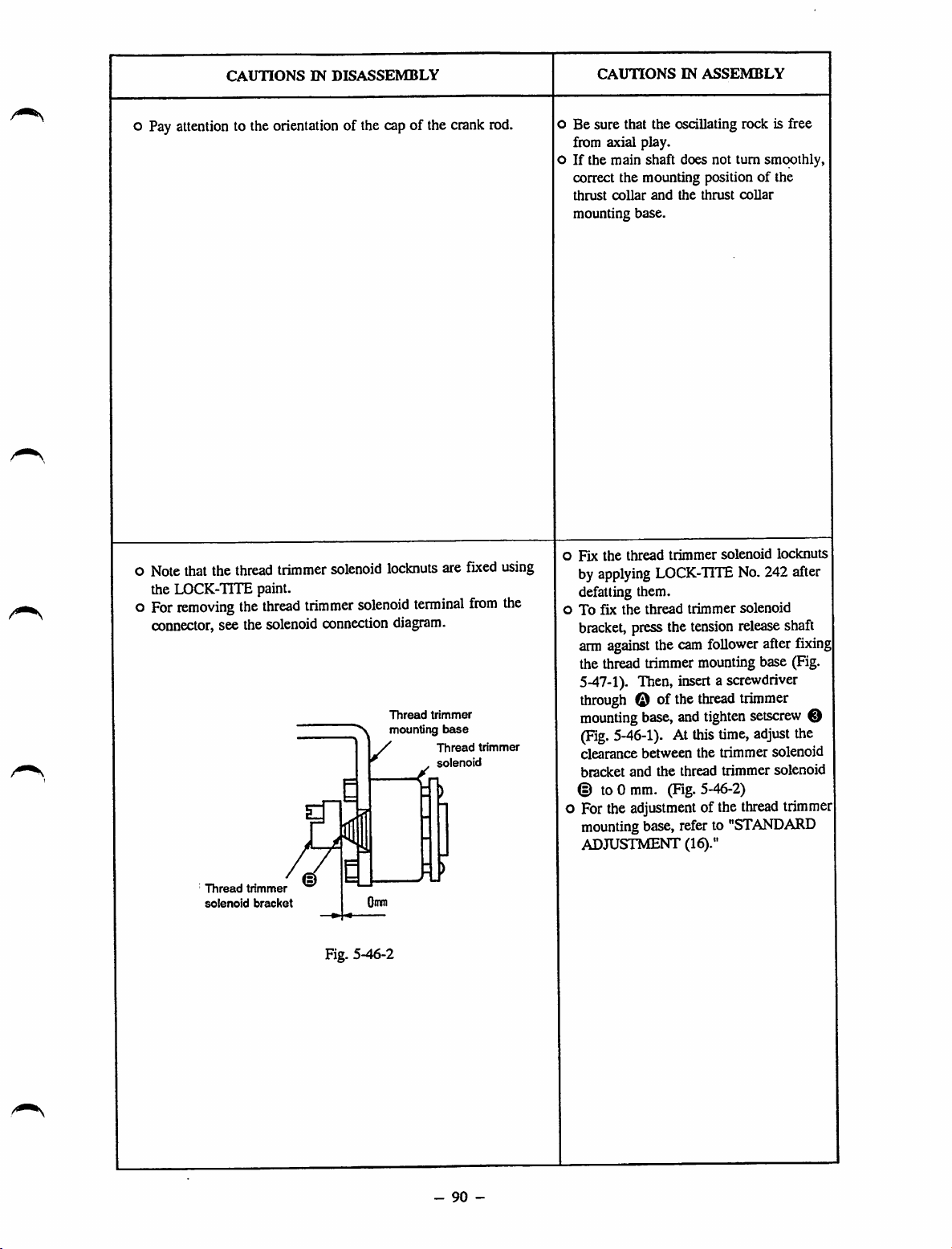
CAUTIONS
IN
DISASSEMBLY
CAUTIONS
IN
ASSEMBLY
o Pay attention to the orientation of the cap of the crank rod.
Note that the thread trimmer solenoid lockouts are fixed using
the LOCK-TITE paint.
For
removing
the
thread
trimmer
solenoid
terminal
from
connector, see the solenoid connection diagram.
Thread
trimmer
mounting
/
' ,
base
Thread
solenoid
trimmer
the
o Be sure that the oscillating rock is free
from axial play,
oIfthe
o
oTofix
main
shaft
does not
correct the mounting position of the
thrust
collar
and
the
mounting base.
Fix
the
thread
trimmer
by
applying
defatting them,
bracket,
arm
against
LOCK-TITE
the
thread
press
the
the
cam
thrust
solenoid
trimmer
tension
follower
turn
smoothly,
collar
No.
242after
solenoid
release
after
lockouts
shaft
fixing
the thread trimmer mounting base (Fig.
5-47-1).
through
mounting
(Fig.
clearance between the trimmer solenoid
bracket
Then,
insertascrewdriver
© of the
base,
5-46-1).Atthis
and
thread
and
tighten
time,
the thread trimmer solenoid
trimmer
setscrew
adjust
the
© to 0 mm. (Fig.5-46-2)
o Forthe
mounting
ADJUSTMENT (16)."
adjustment
base,
referto"STANDARD
of the
thread
trimmer
0
Thread
trimmer
solenoid
bracket
Fig. 5-46-2
-
90
-
Page 100

DISASSEMBLY/ASSEMBLY
PROCEDURES
(47)
Removing
the
tension
release
arm
components
1) Remove the thread trimmer mounting base.
(Refer to "DISASSEMBLY/ASSEMBLY PROCEDURES (46).")
2)
Loosen
setscrewO •
3) Draw out the thread trimming cam shaft in the
direction
of
the arrow (-»). Remove the reset
spring (large), reset spring (small), and the tension
release
shaft
arm.
4) Remove setscrews0,and then remove the cam
follower stopper.
Thread
trimming
Thread
trimming
Tension
reset
reset
release
spring (large)
spring (small)
shaft
arm
(eism.)
Fig. 5-47-1
Cam
Cam
follower
follower
Thread
cam
On
stopper
trimming
shaft
On
(48)
Removing
Remove the thread trimming cam shaft.
1)
the
cam
follower
(See "DISASSEMBLY/ASSEMBLY
PROCEDURES (47).")
Remove the throat plate.
2)
Remove
3)
the
X-Y
table.
(See "DISASSEMBLY/ASSEMBLY
PROCEDURES (55).")
Remove the thread trimming link hinge screw.
4)
Pass
the
cam
5)
follower
under
the
while slightly bending it.
(asm.)
machine
bed
Cam follower (asm.)
Thread
link hinge
OS
trimming
screw
91
-
Fig. 5-48-1
 Loading...