

Page 1

ENGLISH
INStructIoN MaNuaL
aMS-210E / IP-410
aMS-210E / cP-20
* "CompactFlash(TM)" is the registered trademark of SanDisk Corporation, U.S.A.
Page 2

CONTENTS
!
MECHANICAL SECTION (WITH REGARD TO THE SEWING MACHINE) .....
.
1. SPECIFICATIONS ........................................................................................................1
2. CONFIGURATION ........................................................................................................2
3. INSTALLATION ............................................................................................................3
3-1. Installing the electrical box ............................................................................................................3
3-2. Installing and connecting the power switch ................................................................................. 3
3-3. Installation of the sewing machine head ...................................................................................... 4
3-4. Installing the drain receiver and the head support rubber .........................................................5
3-5. Safety switch ................................................................................................................................... 5
3-6. Installing the throat plate auxiliary cover ..................................................................................... 6
3-7. Installing the panel..........................................................................................................................8
3-8.Attachingthepedalchain(ForSspecicationonly) ..................................................................8
3-9. Installing the thread stand .............................................................................................................8
3-10. Raising the machine head ............................................................................................................9
3-11. Connecting the cord ................................................................................................................... 10
3-12. Installing the motor cover .......................................................................................................... 12
3-13. Managing the cord ...................................................................................................................... 13
3-14. Connecting the pneumatic components (Pneumatic type only) ............................................ 13
3-15. Installing the air hose (Pneumatic type only) ...........................................................................16
3-16. Installing the eye protection cover ............................................................................................16
4. PREPARATION OF THE SEWING MACHINE ...........................................................17
4-1. Lubrication.....................................................................................................................................17
4-2. Attaching the needle .....................................................................................................................18
4-3. Threading the machine head .......................................................................................................18
4-4. Installing and removing the bobbin case ...................................................................................19
4-5. Installing the bobbin .....................................................................................................................19
4-6. Adjusting the thread tension .......................................................................................................20
4-7. Intermediate presser height .........................................................................................................21
4-8. Adjusting the thread take-up spring ...........................................................................................22
5. OPERATION OF THE SEWING MACHINE ................................................................22
5-1. Sewing............................................................................................................................................22
5-2. Needle thread clamp device .........................................................................................................23
1
@
.OPERATION SECTION (WITH REGARD TO THE PANEL) ..................... 25
1. PREFACE ...................................................................................................................25
2. WHEN USING IP-410 .................................................................................................28
2-1. Name of each section of IP-410 ................................................................................................... 28
2-2. Buttons to be used in common ...................................................................................................29
2-3. Basic operation of IP-410 ............................................................................................................. 30
2-4. LCD display section at the time of sewing shape selection ..................................................... 32
(1) Sewing shape data input screen ..................................................................................................32
(2) Sewing screen .............................................................................................................................34
2-5. Performing sewing shape selection ............................................................................................ 36
2-6. Changing item data ....................................................................................................................... 38
2-7. Checking pattern shape ...............................................................................................................40
2-8.Performingmodicationofneedleentrypoint .......................................................................... 41
i
Page 3

(1) Changing the thread tension value .............................................................................................. 41
(2) Changing the intermediate presser height value ......................................................................... 42
2-9. How to use temporary stop .......................................................................................................... 43
(1) To continue performing sewing from some point in sewing .........................................................43
(2) To perform re-sewing from the start ............................................................................................. 44
2-10.Whensettingofsewingproductisdifcultbecauseofinterruptionofneedletip .................... 45
2-11. Winding bobbin thread ...............................................................................................................46
(1) When performing winding bobbin thread while performing sewing .............................................46
(2) When performing winding bobbin thread only .............................................................................46
2-12. Using counter ..............................................................................................................................47
(1) Setting procedure of the counter .................................................................................................47
(2) Count-up releasing procedure .....................................................................................................49
(3) How to change the counter value during sewing ......................................................................... 49
2-13. Performing new register of users’ pattern................................................................................50
2-14. Naming users’ pattern ................................................................................................................ 51
2-15. Performing new register of pattern button ............................................................................... 52
2-16. LCD display section at the time of pattern button selection ..................................................53
(1) Pattern button data input screen ..................................................................................................53
(2) Sewing screen .............................................................................................................................55
2-17. Performing pattern button No. selection .................................................................................. 57
(1) Selection from the data input screen ...........................................................................................57
(2) Selection by means of the shortcut button ...................................................................................58
2-18. Changing contents of pattern button ........................................................................................ 59
2-19. Copying pattern button ..............................................................................................................60
2-20. Changing sewing mode .............................................................................................................. 61
2-21. LCD display section at the time of combination sewing ......................................................... 62
(1) Pattern input screen .....................................................................................................................62
(2) Sewing screen .............................................................................................................................64
2-22. Performing combination sewing ...............................................................................................66
(1) Selection of combination data ......................................................................................................66
(2) Creating procedure of the combination data ................................................................................67
(3) Deleting procedure of the combination data ................................................................................ 68
(4) Deleting procedure of the step of the combination data ..............................................................68
2-23. Changing memory switch data ..................................................................................................69
2-24. Using information .......................................................................................................................70
(1) Observing the maintenance and inspection information .............................................................. 70
(2) Releasing procedure of the warning ............................................................................................ 72
(3) Observing the production control information .............................................................................. 72
(4) Performing setting of the production control information ............................................................. 74
(5) Observing the working measurement information ....................................................................... 76
2-25. Using communication function .................................................................................................78
(1) Handling possible data ................................................................................................................78
(2) Performing communication by using the media ........................................................................... 79
(3) Performing communication by using RS-232C ............................................................................ 79
(4) Take-in of the data .......................................................................................................................80
(5) Taking in plural data together ....................................................................................................... 81
2-26. Performing formatting of the media .......................................................................................... 83
3. WHEN USING CP-20 .................................................................................................. 84
3-1. Name of each section of CP-20....................................................................................................84
3-2. Operation of CP-20 (Basic)...........................................................................................................85
ii
Page 4

(1) Item data setting ..........................................................................................................................85
(2) Checking the contour of a sewing pattern ...................................................................................87
(3) Performing modication of the needle entry point .......................................................................88
(4) When the pattern is changed ....................................................................................................... 90
3-3. Performing copying of pattern ..................................................................................................... 90
3-4. Performing deletion of pattern ..................................................................................................... 91
3-5. Sewing............................................................................................................................................92
(1) Change to the other sewing pattern .............................................................................................92
3-6. Winding bobbin .............................................................................................................................93
(1) To wind a bobbin while the sewing machine is performing sewing .............................................. 93
(2) To wind a bobbin independently .................................................................................................. 93
3-7. Operation of CP-20 (Advanced) ...................................................................................................94
(1) Performing sewing using the pattern keys (
(2) Register to the pattern key ...........................................................................................................94
(3) Sewing operation ......................................................................................................................... 96
3-8. Performing sewing using the combination function ................................................................. 97
(1) Register of the combination ......................................................................................................... 97
(2) Sewing operation ......................................................................................................................... 98
3-9. When using as "bobbin thread counter" .................................................................................... 99
(1) How to use the temporary stop .................................................................................................... 99
3-10. Start and change of the memory switch .................................................................................100
3-11. Correspondence table of LED and 7-segment display .......................................................... 101
, , , and ) ........................ 94
4. MEMORY SWITCH DATA LIST ................................................................................ 104
4-1. Data list ........................................................................................................................................ 104
4-2. Initial value list ............................................................................................................................110
5. ERROR CODE LIST ................................................................................................. 112
6. MESSAGE LIST ....................................................................................................... 118
#
. MAINTENANCE OF SAWING MACHINE .............................................. 121
1. MAINTENANCE ........................................................................................................ 121
1-1. Adjusting the height of the needle bar (Changing the length of the needle) ........................ 121
1-2. Adjusting the needle-to-shuttle relation ................................................................................... 121
1-3. Adjusting the height of the feeding frame ................................................................................ 123
1-4. Adjusting the vertical stroke of the intermediate presser ....................................................... 123
1-5. The moving knife and counter knife..........................................................................................124
1-6. Needle thread clamp device ....................................................................................................... 124
1-7. Thread breakage detector plate ................................................................................................ 125
1-8. Draining waste oil .......................................................................................................................125
1-9. Amount of oil supplied to the hook ........................................................................................... 126
1-10. Replacing the fuse .................................................................................................................... 126
1-11. Changing the voltage of 100
1-12. Replenishing the designated places with grease .................................................................. 128
1-13. Troubles and corrective measures (Sewing conditions).......................................................131
200V ..................................................................................... 127
,/
2. OPTIONAL ................................................................................................................ 133
2-1. Table of Needle hole guide ......................................................................................................... 133
2-2. Silicon oil tank ............................................................................................................................ 133
iii
Page 5
!
. MECHANICAL SECTION (WITH REGARD TO THE SEWING MACHINE)
1. SPECIFICATIONS
1 Sewing area X (lateral) direction Y (longitudinal) direction
AMS-210E-1306 : 130 mm ×
AMS-210E-1510 : 150 mm ×
AMS-210E-2206 : 220 mm ×
AMS-210E-2210 : 220 mm ×
2
Max. sewing speed 2,700 rpm (When sewing pitch is 3 mm or less)
3 Stitch length 0.1 to 12.7 mm (Min. resolution : 0.05 mm)
4
Feed motion of feeding frame
5 Needle bar stroke 41.2 mm
6 Needle DP x 5, DP x 17
Lift of feeding frame Max. 25mm (Pneumatic type only Max.30mm)
7
8
Intermediate presser stroke
Lift of intermediate
9
presser
Intermediate presser
10
DOWN position
variable
11 Shuttle
12 Lubricating oil New Defrix Oil No. 2 (Supplied by oiler)
13 Memory of pattern
data
14 Temporary stop facility Used to stop machine operation during a stitching cycle.
15 Enlarging / Reducing
facility
16 Enlarging / Reducing
method
17
Max. sewing speed
limitation
18
Pattern selection
facility
19 Bobbin thread counter UP/DOWN method (0 to 9,999)
Sewing counter UP/DOWN method (0 to 9,999) (IP-410 only)
20
21 Memory back-up
2nd origin setting
22
facility
Sewing machine motor Servo-motor
23
24
Dimensions
25 Mass (gross mass) Machine head 69kg, control box 16.5kg
26 Power consumption 500 VA
Operating temperature
27
range
28
Operating humidity range
29 Line voltage Rated voltage ±10% 50 / 60 Hz
Air pressure used Standard 0.35 to 0.4 MPa (Max. 0.55 MPa)(Pneumatic type only)
30
31 Air consumption 1.8 dm3 / min (ANR) (Pneumatic type only)
32 Needle highest
position stop facility
33 Noise Workplace-related noise at sewing speed
Intermittent feed (2-shaft drive by stepping motor)
4 mm (Standard) (0 to 10 mm)
20 mm
Standard 0 to 3.5 mm (Max. 0 to 7.0 mm)
Double-capacity semi-rotary hook
EEPROM , Media
• EEPROM : Max. 200 patterns (Max. 20,000 stitches/pattern)
• Media : Max. 999 patterns (Max. 50,000 stitches/pattern)
Allows a pattern to be enlarged or reduced on the X axis and Y axis independently
when sewing a pattern. Scale : 1% to 400% times (0.1% steps)
Pattern enlargement / reduction can be done by increasing / decreasing either stitch
length or the number of stitches. (Only increase/decrease of stitch length when pattern
button is selected and CP-20 is used)
200 to 2,700 rpm (Scale : 100 rpm steps)
Pattern No. selection method
(EEPROM : 1 to 200, Media : 1 to 999)
(CP-20 is the scroll type.)
In case of a power interruption, the pattern being used will automatically be stored in
memory.
Using jog keys, a 2nd origin (needle position after a sewing cycle) can be set in the
desired position within the sewing area. The set 2nd origin is also stored in memory.
(IP-410 only)
1,200mm (W) x 710mm (L) x 1,200mm (H)
5˚C to 35˚C
35 % to 85 % (No dew condensation)
After the completion of sewing, the needle can be brought up to its highest position.
n = 2,700 min
Noise measurement according to DIN 45635-48-B-2-KL2
–1
: Lpa ≦ 84dB(A)
60 mm
100 mm
60 mm
100 mm
(Excluding thread stand)
– 1 –
Page 6

2. CONFIGURATION
2
3
4
6
1
7
5
!1
Machine head
1
Wiper switch
2
Temporary stop switch
3
Feeding frame
4
Intermediate presser
5
Thread stand
6
Operation panel (IP-410 or CP-20)
7
Power switch
8
Control box
9
Foot pedal
!0
Manual pedal (Excluding pneumatic type)
!1
8
9
!0
Air regulator
(for pneumatic type only)
– 2 –
Page 7

3. INSTALLATION
3-1. Installing the electrical box
5
6
7
1
2
3
4
Install the electrical box on the underside of the
table at the location illustrated using round-head
bolt 1, plain washer 2, spring washer 3 and nut
supplied with the machine, and using bolt hav-
4
ing hexagonal indentation on the head 5 spring
washer 6 and plain washer 7 supplied with the
machine.
3-2. Installing and connecting the power switch
1) Installing the power switch
3
Fix power switch 1 under the machine table
with wood screws 2.
Fix the cable with staples 3 supplied with the
machine as accessories in accordance with the
forms of use.
1
2
Five staples 3 including the staple
for xing the operation panel cable
are supplied as accessories.
– 3 –
Page 8
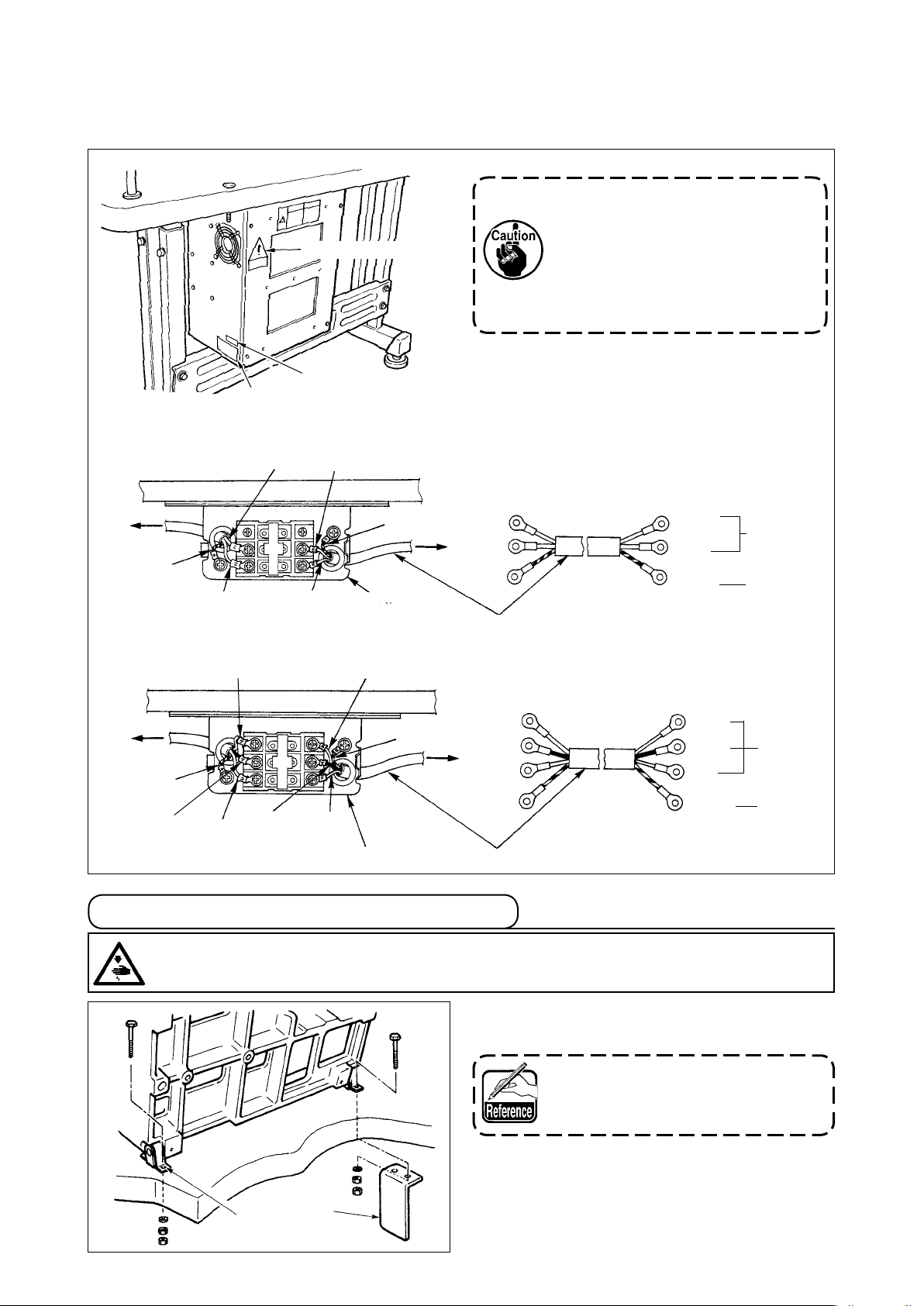
(2) Connecting the power source cord
Voltage specications at the time of delivery from the factory are indicated on the voltage indication
seal. Connect the cord in accordance with the specications.
1. Never use under the wrong volt-
age and phase.
Voltage caution seal
2. When changing the voltage,
refer to the item of
"#-1-11. Changing the voltage
of 100
Voltage indication seal (3-phase type only)
Rating label
200V" p.127.
,/
• Connecting single phase 200V, 220V, 230V and 240V
Light blue
Table
Control box
Green/Yellow
Brown
Brown
Light blue
Green/Yellow
Power switch
Plug
Power source cord
Brown
Light
blue
Green/
Yellow
AC200 V
AC220 V
AC230 V
AC240 V
GND
• Connecting three phase 200V, 220V and 240V
White
White
Table
Green/Yellow
Control box
Green/Yellow
Black
Red
Black
Red
Power switch
Plug
Power source cord
3-3. Installation of the sewing machine head
WARNING :
To prevent possible accidents caused by the full of the sewing machine, perform the work by two
persons or more when the machine is moved.
1) Fit the holes of hinges A to the holes of table
White
Black
Red
Green/
Yellow
and x as shown in the gure.
In case of the pneumatic type, x
solenoid valve installing plate 1 as
well.
AC200 V
AC220 V
AC240 V
GND
A
1
– 4 –
Page 9

3-4. Installing the drain receiver and the head support rubber
1) Fix drain receiver 2 in the installing hole of
table 1 with two setscrews 3.
2) Screw in drain bin 4 to drain receiver 2.
7
1
6
6
6
3
6
2
6
5
3) Insert sewing machine drain pipe 5 into drain
bin 4.
4) Insert head support rubbers 6 to machine bed 7.
5) Bundle the cables with clip bands 8 as shown
in the gure. (Excluding air tube)
1. Insert drain pipe 5 until it will
8
2. Remove the tape xing drain pipe
go no further so that it does not
come off drain bin 4 when tilting
the machine head.
.
5
4
3-5. Safety switch
1
6
Remove tape 2 xing the lever section of safety
switch
1. When using the safety switch
2. In case error 302 occurs when
1
.
without removing tape 1, it is
very dangerous since the sewing
machine works even in the state
that it is tilted.
the sewing machine works after
setup, loosen the safety switch
tting screw with a screwdriver,
and lower the switch to the down-
side of the sewing machine.
2
2
– 5 –
Page 10
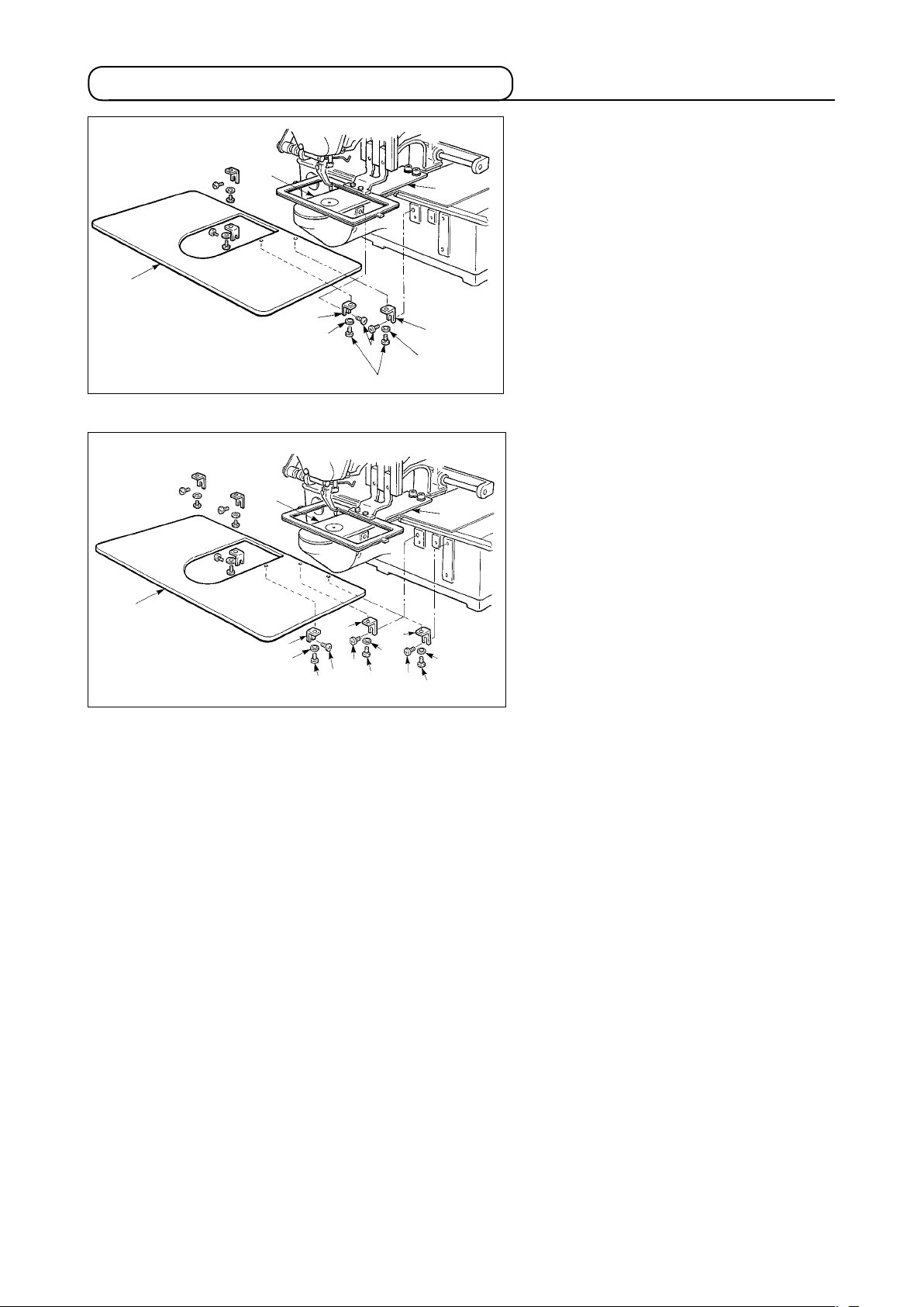
3-6. Installing the throat plate auxiliary cover
[Area 1306]
1
[Areas 1510 and 2206]
1
8
8
2
4
2
4
5
6
3
6
6
5
5
4
9
!0
4
5
3
7
7
4
[When using area 1306]
1) Temporarily x throat plate auxiliary
cover supports A 2 and B 3 to the
machine bed with setscrews (M5)6.
2) Move the cloth feed base to the rear,
and place throat plate auxiliary cover
from between lower plate 7 and
1
throat plate 8. At this time, be careful
not to bend lower plate 7.
3) Fix throat plate auxiliary cover 1 with
throat plate auxiliary cover setscrews
and washers 4.
5
[When using areas 1510 and 2206]
1) Temporarily x throat plate auxiliary
supports A 2 and B 3 to the machine
bed with setscrews (M5) 6 and throat
plate auxiliary support C 9 to the ma-
chine bed with setscrew (M6)
!0
.
2) Move the cloth feed base to the rear,
and place throat plate auxiliary cover
from between lower plate 7 and
1
throat plate 8. At this time, be careful
not to bend lower plate 7.
3) Fix throat plate auxiliary cover 1 with
throat plate auxiliary cover setscrews
and washers 4.
5
– 6 –
Page 11
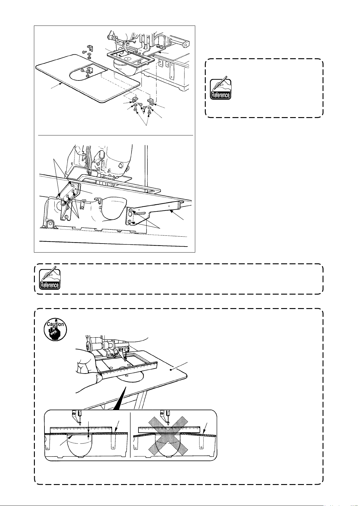
[Area 2210]
1
[Area 2210]
!5
5
!4!5
!3
8
2
4
6
5
!2
4
3
7
!1
[When using area 2210]
1) Temporarily x throat plate auxiliary
cover supports A 2 and B 3 to the
machine bed with setscrews (M5)6.
For the screw 6which tightens the throat plate auxiliary
cover support A
screw which is easier to use
between the hexagon socket
and the screw with plus and
minus slots.
, select the
2
2) Move the cloth feed base to the rear,
and place throat plate auxiliary cover
from between lower plate 7 and
1
throat plate 8. At this time, be careful
not to bend lower plate 7.
Fix
3)
throat plate auxiliary cover 1 with
throat plate auxiliary cover setscrews
and nuts (small) 4.
5
emporarily fix throat plate auxiliary
4) T
cover support !1 to the machine bed
with setscrews (M6) !2.
emporarily fix throat plate auxiliary
5) T
cover base
to throat plate auxiliary
!3
cover support !1 with setscrews !4 and
nuts (large) !5.
Fix
6)
throat plate auxiliary cover 1 with
throat plate auxiliary cover setscrews
and nuts (large) !5.
5
Left-hand and right-hand shapes of throat plate auxiliary cover support !1 are different.
So, be careful.
1. Be careful so as not to mistake the direction of throat
plate auxiliary cover support.
8
Within 0.3 mm
1
2.
1
1
Fix the throat plate auxiliary
cover 1so that is higher
than the throat plate
(within 0.3 mm). When it is
lower than the throat plate
, needle breakage or the
8
like due to the defective
feed will be caused.
3.
Conrmbyputtingaruler
or the like that the throat
plate auxiliary cover 1is
horizontally installed. If not,
throat plate auxiliary cover
and lower plate 7 come
1
in contact partially with
each other
worn-out will be caused.
, and abnormal
8
– 7 –
Page 12
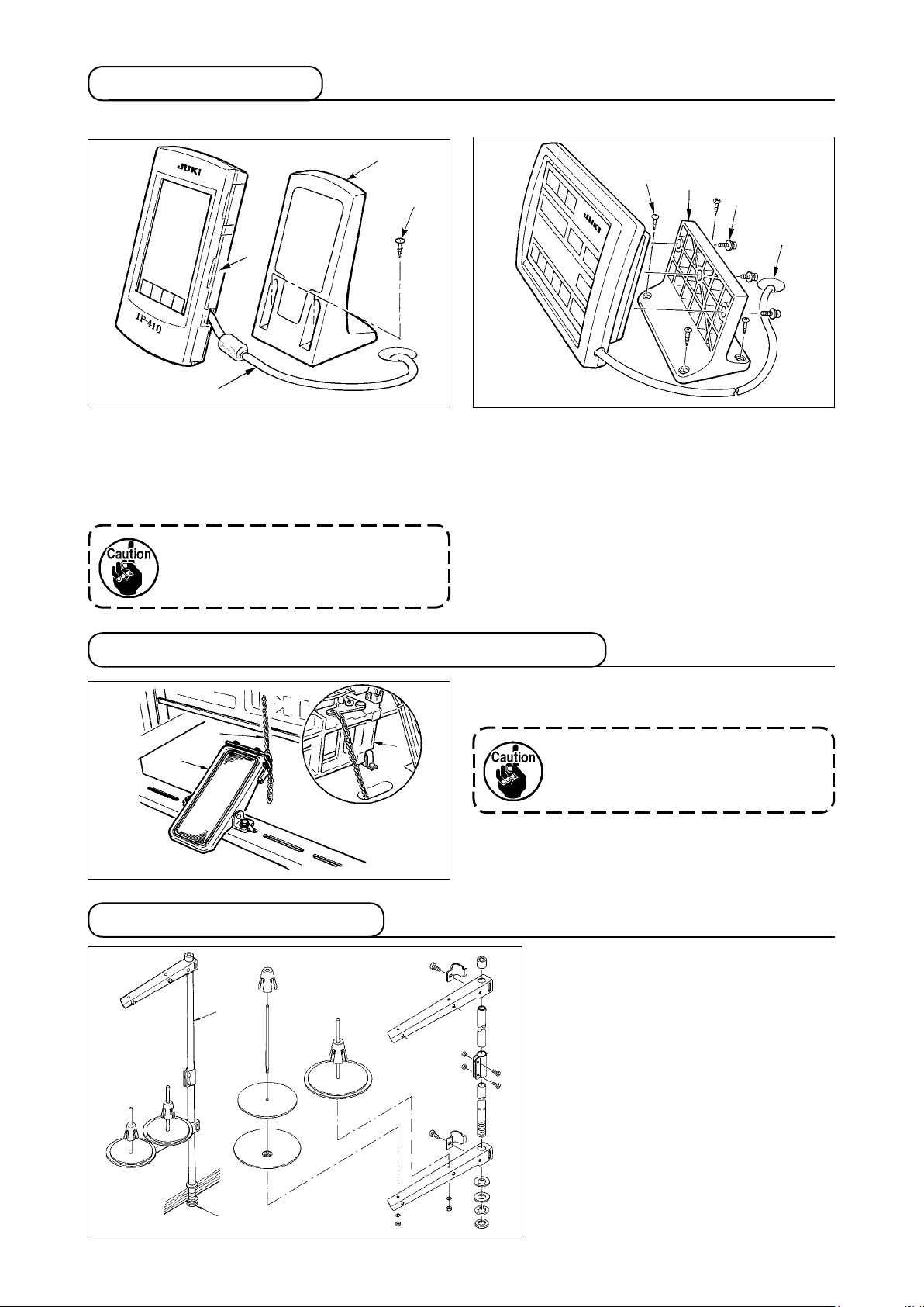
3-7. Installing the panel
1) Installing the IP-410
3
4
1
2
1) Open cover 1 and remove cable 2 once.
Then connect it again to the panel on the top
surface of the table after passing it through the
hole in the table.
2) Fix operation panel installing plate 3 to an optional place on the table with two wood screws 4.
Install the panel at the position
where X-move cover or head grip
does not interfere with it since
breakage of the panel will be caused.
2) Installing the CP-20
2
1
3
4
Fix operation panel installing plate 1 to an optional place on the table with wood screws 2, and
pass the cable through table hole 4.
Fix the operation panel on panel installing plate 1
with screws 3 supplied as accessories.
Fix the cable on the bottom surface of the table
with the staples supplied with the machine as accessories.
3-8.Attachingthepedalchain(ForSspecicationonly)
Connect the machine 1 and manual pedal 3 with
chain 2.
3
2
1
When you tilt the sewing machine,
be sure to tilt it after removing chain
from manual pedal 3.
2
3-9. Installing the thread stand
1) Assemble the thread stand, and put
2
2) Tighten locknut 1 to x the thread
3) When ceiling wiring is possible,
it in the hole in the top left corner of
the machine table.
stand.
pass the power cord through spool
rest rod 2.
1
– 8 –
Page 13
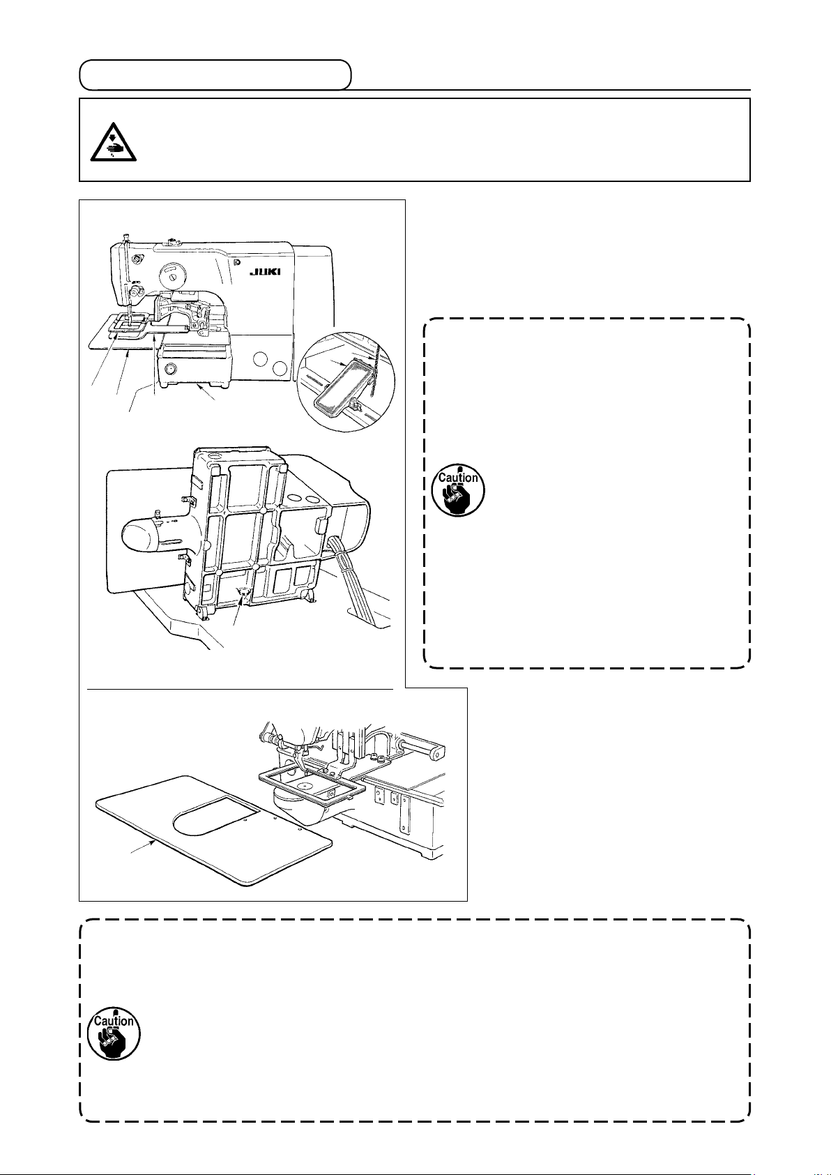
3-10. Raising the machine head
WARNING :
Tilt/raise the sewing machine head with both hands taking care not to allow your ngers to be
caught in the head.
Turn OFF the power before starting the work so as to prevent accidents caused by abrupt start of
the sewing machine.
4
6
5
A
3
1
2
[When using areas 1306 and 1510]
When raising the sewing machine, hold inserting
section A of the machine bed by hand, and quietly
raise it until bed support rubber 3 comes in contact
with the table. For the S type, remove chain 2 from
manual pedal 1 rst, and perform the work.
1. Be sure to raise the machine head
at the leveled place so as to prevent
the sewing machine from falling.
2. When raising the machine head,
move feeding frame 4 beforehand to the right-hand side until
it goes no further, and x it with
tape or the like. When the machine head is raised in the state
that moving or xing is insufcient, breakage of X-move cover
or X-move rail will be caused.
Besides, feeding frame 4 which
is tilted to the left-hand side by
the self-weight interferes with the
intermediate presser or the like
and breakage of the components
will be caused.
[Areas 2206 and 2210]
[When using areas 2206 and 2210]
1) Remove throat plate auxiliary cover
from the sewing machine.
6
2) Hold inserting section
of the ma-
A
chine bed by hand, and quietly raise
it until bed support rubber 3 comes
in contact with the table.
3) After returning the sewing machine
to its home position, refer to “!-3-6.
6
Installing the throat plate auxiliary cover” p.6
, and install the throat
plate auxiliary cover.
1. Be sure to raise the machine head at the leveled place so as to prevent the sewing
machine from falling.
2. When raising the sewing machine without removing throat plate auxiliary cover 6,
the throat plate auxiliary cover interferes with the table, bend or breakage of the
throat plate auxiliary cover, tilt of the sewing machine, etc. will result.
3. When raising the machine head, move feeding frame 4 beforehand to the right-hand
side until it goes no further, and x it with tape or the like. When the machine head is
raised in the state that moving or xing is insufcient, breakage of X-move cover or
X-move rail will be caused. Besides, feeding frame 4 which is tilted to the left-hand
side by the self-weight interferes with the intermediate presser or the like and breakage of the components will be caused.
– 9 –
Page 14

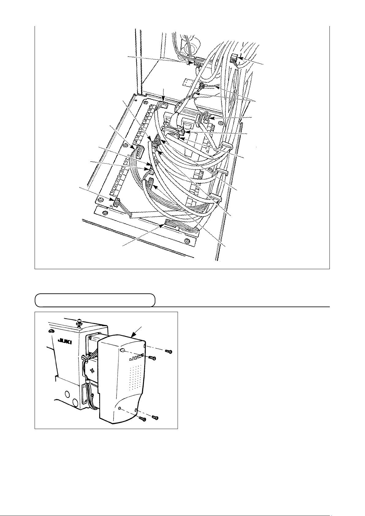
3-11. Connecting the cord
[How to open the control box]
Remove four screws 1 xing the rear cover of
the electrical box. When opening the rear cover,
pressing it with your hands, slowly open it by ap-
proximately 90˚ until it stops as illustrated.
1
Be sure to lend your hand to the rear
cover in order not to let the rear cover
Slowly
fall. In addition, do not apply force to
the rear cover opened.
[How to close the control box]
1) Take care so that the cord is not
2
caught between the rear cover and
the electrical box main body, close the
C
1
A
B
the lower side of the rear cover, and
tighten four screws
1
.
2) Lower downward the cord located on
rear cover while pressing section
A
on
the side of the control box and cord
presser plate C in the push hole
press the cord and tighten screws
,
B
.
2
How to lock the cord clamp
Lightly press
1
the corner
of clamp.
(Cord clamp is
locked with a
click.)
When xing the cord with the cord clamp, be careful of the route or the like so that the
stress is not applied to the cord.
1
1
2
Clamp
How to remove the cord clamp
Lightly pressing
1
Pull down the clamp.
2
The clamp goes up.
3
1
3
2
1
– 10 –
Page 15

[Wiring diagram of circuit board]
SDC p.c.b.
MAIN p.c.b.
CN14
CN16
CN38
CN72
CN39
CN71
CN73
CN74
CN75
CN47
CN51
CN51
9P
4P
20P
4P
2P
5P
5P
4P
6P
2P
10P
10P
White
White
Gray
Blue
Yellow
Red
White
White
White
White
White
White
White
White
CN88
10P
CN88
10P
Sewing machine head
Foot switch
2P
1
2P
1
2
2
2P
3
2P
4
2P
5
2P
3P
3
4
1306
CN51
CN34
CN84
CN52
10P
26P
10P
2P
Black
W
hite
White
White
Gray
CN88
10P
White
White
10P
4P
1
2
3
4
5
CN98
CN78
2P
2P
2P
2P
2P
10P
4P
1
2
4
3
Gray
White
White
3P
CN100
26P
CN1
2P
2P
CN2
1510
Operation panel
IP-410
CP-20
Air
solenoid
valve
Air SW
– 11 –
Page 16
CN16 White
CN14 White
CN71 Red
CN72
Blue
CN52
White
CN31
White
CN51
White
CN73 White
CN39
Yellow
Ground wire
CN74 White
CN34 Gray
CN38 Gray
CN75 White
CN47 White
CN84 Black
3-12. Installing the motor cover
1
Install motor cover 1 on the machine main unit
with screws supplied with the machine as acces-
sories.
– 12 –
Page 17
3-13. Managing the cord
1
Slack
1) Fix the cords with cords setting plate
in the state that the cords are slack to such an extent that
1
stress is not applied to the cords even when the machine head is tilted as shown in the gure.
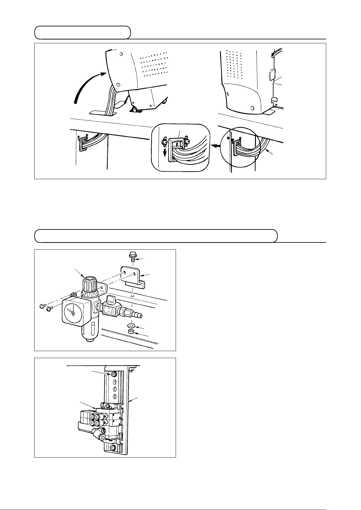
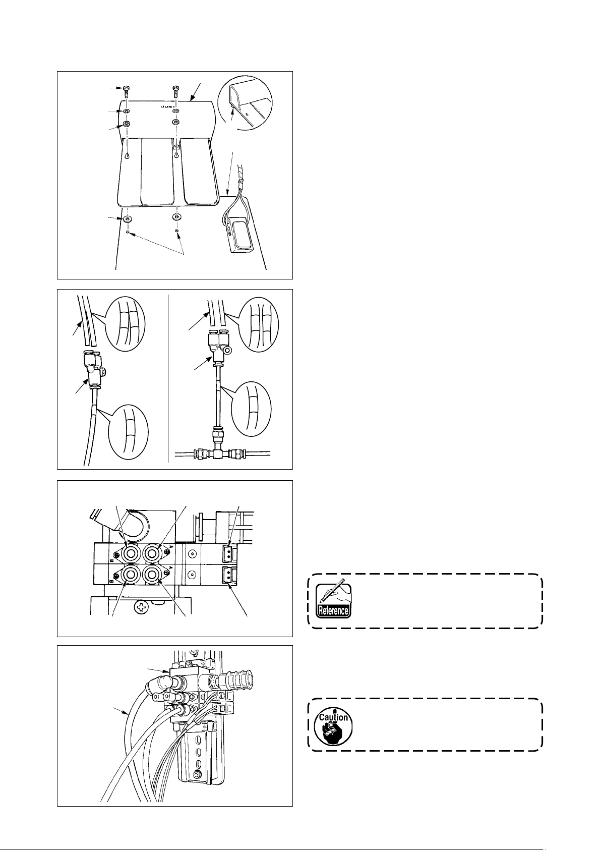
3-14. Connecting the pneumatic components (Pneumatic type only)
3
1
2
4
5
7
1) Install regulator 1 to installing plate
install it to the stand with screw
3
and nut 5.
2) Connect the cord coming from the regulator
with CN78 (air relay cable).
(Refer to
!
"
-3-11. [Wiring diagram of circuit board]"
.)
p.11
3) Install solenoid valve asm. 8 to solenoid valve
installing plate 6 using setscrew 7 supplied
as accessories.
, and
2
, washer 4
8
6
– 13 –
Page 18

!0
9
[When using areas 1306, 1510 and 2206]
4) Fix the air tube using cable clip
supplied with
9
the machine as accessories. (For the setscrew,
use setscrew !0 xing the motor cover.)
Connector
CN1
Connector
CN2
Air tube
1A
Air tube
2A
8
Air tube
1B
Air tube
2B
!1
5) Install air tubes coming from the machine head
and the cords coming from the control box to
the position as shown in the gure. At this time,
be careful of the number and alphabet of the
air tubes and the cords. (Adjust the alphabet
of the air tubes to the alphabet of the solenoid
valve. Also, adjust the gures to the gures of
the connector label.)
6) Connect solenoid valve asm.
lator using long air tube supplied
and the regu-
8
as acces-
!1
sories.
When the cable sags, x it to the
table using the staple supplied with
the machine as accessories.
– 14 –
Page 19
[When using area 2210]
!5
!7
!2
!1
!3
!0
!4
!3
5) Remove once two setscrews
ers (small)
washers (large)
valve unit
, two spring washers
!1
attached to mechanical
!3
. Refer to the gure, and install
9
, two wash-
!0
!2
and two
2-pedal type pedal !4 into hole A of mechani-
9
A
cal valve unit 9.
6) Connect the air tubes coming from the machine
2A
1A
1B
2B
!6
head and Y-type joint respectively as described
below.
• Air tube !5 with label of "1A, 2A"
Y-type joint !7 connected with the label of
/
!8
"3" of mechanical valve unit
• Air tube !6 with label of "1B, 2B"
4
3
Y-type joint !8 connected with the label of
/
"4" of mechanical valve unit
Stop plug
B
!9
8
Stop plug
A
Connector
CN2
Connector
CN1
7) Install the air tube coming from mechanical
valve unit "7" to
, and that from "8" to B re-
A
spectively.
Install two stop plugs supplied as accessories,
and the cords coming from the control box to
the places in the gure.
When the mechanical valve is not
used, refer to [When using areas
1306, 1510 and 2206].
8) Connect solenoid valve asm.
lator using long air tube supplied
and the regu-
8
as acces-
!9
sories.
When the cable sags, x it to the
table using the staple supplied with
the machine as accessories.
– 15 –
Page 20
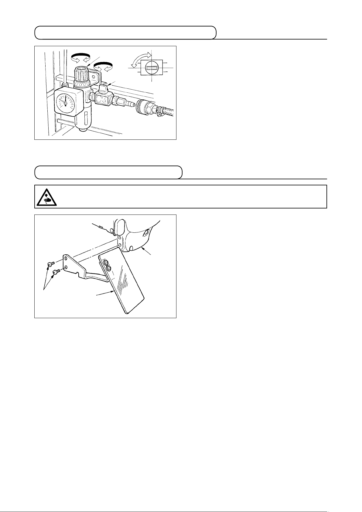
3-15. Installing the air hose (Pneumatic type only)
2
Open
1
Close
3-16. Installing the eye protection cover
WARNING :
Be sure to attach this cover to protect the eyes from the disperse of needle breakage.
1) Connecting the air hose
Connect the air hose to the regulator .
2) Adjustment of air pressure
Open air cock 1, pull up and turn air adjust-
ment knob 2 and adjust so that air pressure
indicates 0.35 to 0.4 MPa (Max. 0.55 MPa).
Then lower the knob and x it.
* Close air cock 1 to expel air.
Use eye protection cover
taching it on face plate cover 3 with screw
after securely at-
1
2
.
2
3
1
– 16 –
Page 21
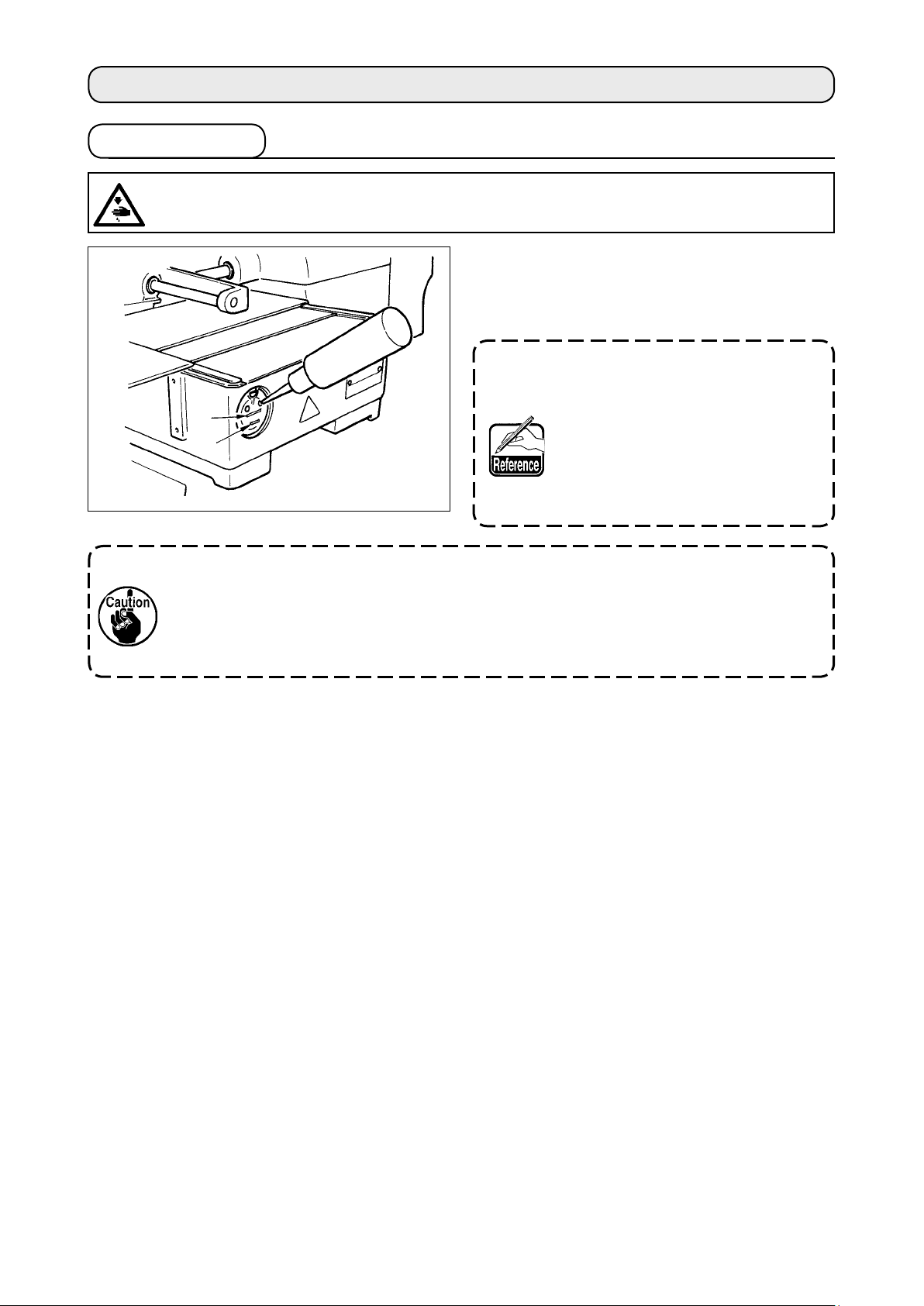
4. PREPARATION OF THE SEWING MACHINE
4-1. Lubrication
WARNING :
Turn OFF the power before starting the work so as to prevent accidents caused by abrupt start of
the sewing machine.
Check that the place between lower line B and up-
per line A is lled with oil. Fill there with oil using
the oiler supplied with the machine as accessories
when oil is short.
The oil tank which is lled with oil
A
B
is only for lubricating to the hook
portion. It is possible to reduce
the oil amount when the number
of rotation used is low and the oil
amount in the hook portion is excessive. (Refer to “#-1-9. Amount
of oil supplied to the hook” p.126 .)
1. Do not lubricate to the places other than the oil tank and the hook of Caution 2 below.
Trouble of components will be caused.
2. When using the sewing machine for the rst time or after an extended period of dis-
use, use the machine after lubricating a small amount of oil to the hook portion. (Refer
to “#-1-2. Adjusting the needle-to-shuttle relation” p.121. )
– 17 –
Page 22
4-2. Attaching the needle
WARNING :
Turn OFF the power before starting the work so as to prevent accidents caused by abrupt start of
the sewing machine.
Loosen setscrew 1 and hold needle 2 with the long
groove facing toward you. Then fully insert it into the
hole in the needle bar, and tighten setscrew 1.
1
1.5mm
2
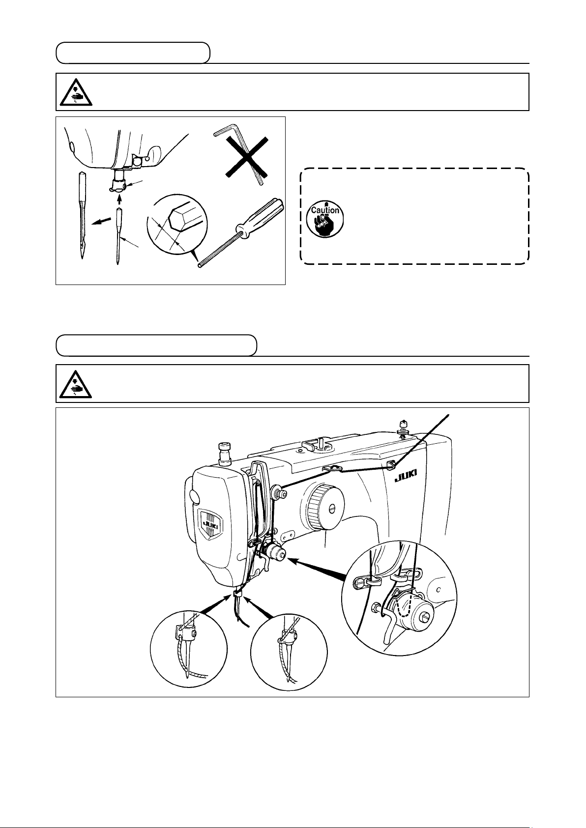
4-3. Threading the machine head
WARNING :
Turn OFF the power before starting the work so as to prevent accidents caused by abrupt start of
the sewing machine.
When tightening setscrew
1
, be
sure to use the screwdriver (Part No.
: 40032763) supplied as accessories.
Do not use L-shaped hexagon wrench
key. There is a danger of breaking
setscrew 1.
AMS-210ESS
AMS-210ESL
AMS-210EHS
AMS-210EHL
– 18 –
Page 23

4-4. Installing and removing the bobbin case
WARNING :
Turn OFF the power before starting the work so as to prevent accidents caused by abrupt start of
the sewing machine.
1
4-5. Installing the bobbin
WARNING :
Turn OFF the power before starting the work so as to prevent accidents caused by abrupt start of
the sewing machine.
2.5 cm
4
3
1
2
2
3
5
1) Open hook cover
2) Raise latch 3 of bobbin case
1
.
, and remove
2
the bobbin case.
3) When entering bobbin case, insert it with the
latch tilted until "click" sounds.
If it is not fully inserted, bobbin case
may slip off during sewing.
2
1) Set the bobbin 1 into bobbin case 2 in the di-
rection shown in the gure.
2) Pass the thread through thread slit
of bob-
3
bin case 2, and pull the thread as it is. By so
doing, the thread will pass under the tension
of the
5
4
.
spring and be pulled out from thread hole
3) Pass the thread through thread hole
horn section, and pull out the thread by 2.5 cm
from the thread hole.
If the bobbin is installed in the bobbin
case orienting the reverse direction,
the bobbin thread pulling out will result
in an inconsistent state.
– 19 –
Page 24

4-6. Adjusting the thread tension
1
Longer
Shorter
Adjusting the needle thread tension
[IP-410]
If thread tension controller No. 1 1 is turned
clockwise, the length of remaining thread on the
needle after thread trimming will be shorter. If it is
turned counterclockwise, the length will be longer.
Shorten the length to an extent that the thread is
2
not slipped off.
Adjust needle thread tension from the operation
panel and bobbin thread tension with
1) Select THREAD TENSION button
2
.
[CP-20]
A
h
in the sewing screen.
A
2) Set needle thread tension with TEN
keys B. There is a setting range of 0 to
200. When the set value is increased,
B
1) Select thread tension with key.
2) Set needle thread tension with key or
When the set value is increased, the tension
becomes higher.
* When the set value is 50 at the time of stan-
dard delivery, the thread tension is adjusted so
that H type is 2.35N and S type is 1.47N (spun
thread #50).(When thread tension No. 1 is re-
leased)
the tension becomes higher.
* When the set value is 50 at the time of
standard delivery, the thread tension is
adjusted so that H type is 2.35N and S
type is 1.47N (spun thread #50). (When
thread tension No. 1 is released)
key. There is a setting range of 0 to 200.
– 20 –
Page 25

4-7. Intermediate presser height
When raising the intermediate presser height, turn the pulley by hand to lower the needle
bar, and conrm that the needle bar does not interfere with the intermediate presser. (When
using DP X 5 needle, use the sewing machine with the height of 3.5 mm or less.)
[IP-410]
A
Press INTERMEDIATE PRESSER SETTING button A and adjust
B
with TEN keys
intermediate presser and the cloth is 0.5 mm (thickness of thread
used).
so that the clearance between the bottom end of
B
0.5 mm
[CP-20]
1) Select the intermediate presser with key.
2) Press key to lower the intermediate
presser.
h
1. Setting range of the intermediate presser is up to the standard of 3.5 mm.
However, when using DP X 17 needle for H type or the like, the setting range can be
changed up to max. 7 mm with memory switch U112.
2. When increasing the height of intermediate presser or making the needle size thicker,
conrm the clearance between the wiper and the components. Wiper cannot be used
unless the clearance is secured. In this case, turn OFF the wiper switch, or change
the set value of memory switch U105.
3) Adjust with or key so that the
clearance between the bottom end of
intermediate presser and the cloth is 0.5 mm
(thickness of thread used) when the needle is in
its lowest position.
– 21 –
Page 26

4-8. Adjusting the thread take-up spring
1
3
1) Adjusting the stroke
Loosen setscrew 2, and turn thread tension asm. 3.
Turning it clockwise will increase the moving
4
amount and the thread drawing amount will
increase.
Increase
Decrease
2) Adjusting the pressure
To change the pressure of the thread take-
up spring 1, insert a thin screwdriver into the
slot of thread tension post 4 while screw 2 is
tightened, and turn it. Turning it clockwise will
increase the pressure of the thread take-up
2
spring. Turning it counterclockwise will decrease the pressure.
5. OPERATION OF THE SEWING MACHINE
5-1. Sewing
2P pedal
A
e
B
[In case of 2P pedal]
1) Set a workpiece on the sewing machine.
2) Depress the pedal switch A, and the feeding
frame will come down. Depress it again, and
the feeding frame will go up.
3) Depress the pedal switch B after the feeding
frame has come down and the sewing machine
will start sewing.
4) After the sewing machine completes sewing,
the needle point will return to the start point
and the feeding frame will go up.
3P pedal
[In case of 3P pedal]
1) Set a workpiece on the sewing
machine.
2) When pedal switch A is depressed, the right-hand presser
comes down, and when it is
depressed again, the presser
goes up. When pedal switch
is depressed, the left-hand
A
B
C
B
presser comes down, and
when it is depressed again, the
presser goes up.
3) Depress the pedal switch C after the feeding frame has come down and the sewing machine will
start sewing.
4) After the sewing machine completes sewing, the needle point will return to the start point and the
feeding frame will go up.
When using the area 1510 with the standard method, the use of 3P pedal is the same as
that of 2P pedal. Refer to [In case of 2P pedal].
When using the pedal as 3P pedal by remodeling the presser or the like, it is necessary
to change the connecting procedure of the pedal and memory switches
U81 and U82.
– 22 –
Page 27
5-2. Needle thread clamp device
By actuating the needle thread clamp device, trouble of sewing at the high-speed start (needle thread
slip-off, stitch skipping or needle thread stain) is prevented, and can reduce gathering (bird's nest) of
needle thread on the wrong side of cloth while keeping stable sewing. Needle thread clamp device
operates in the state that thread clamp display LED is lit, and does not operate when it goes off. When
mounting the IP-410, changeover of motion ON/OFF is performed with key, and when mounting
the CP-20 , changeover of motion ON/OFF is performed with key respectively. When the needle
thread clamp device is OFF, the machine automatically operates at slow-start.
When memory switch No. 35 is "1" (prohibited), the thread clamp does not work. In addi-
tion,
and key is ineffective.
For the thread clamp unit, there are S type and H type in accordance with the sewing types. Refer the
respective types and the contents of the memory switches that can be set to the list below.
Sewing machine
type
AMS-210ESS
AMS-210ESL
AMS-210EHS
AMS-210EHL
Thread clamp unit type
S type
H type
0 : S type (standard)
1 : H type thin thread (standard)
(#50 to #8)
2 : H type intermediate
3 : H type thick thread (#5 to #2)
Memory switch
U69
U70
0 : Front (standard)
0 : Front (standard)
or
1 : Rear
[Regarding H type thread clamp unit]
Change the set value of memory switch U69 in accordance with the thickness of needle thread. The set
value has been set to 1 : H type thin thread at the time of delivery. Commendable value is Set value : 1
for thread count #50 to #8, and that is Set value : 3 for thread count #5 to #2. (The value will change in
accordance with the kind and thickness of the actual thread and the kinds of materials to be sewn.) Set
the value by adjusting to the state of needle thread on the wrong side of materials.
In addition, it is possible to select the thread clamp position by means of memory switch U70. When
using thick thread of thread count #5 to #2, and rolling-in or tucking at the start of sewing occurs, set the
set value to 1 : Rear and use the machine.
Use the set value of the memory switch which is adjusted to the thread clamp unit type.
(For S type thread clamp unit, the set value of U69 and U70 can use nothing but only "0".
When the setting is wrong, the thread clamp fails to properly function. So, be careful.
– 23 –
Page 28

(1) When with thread clamp (motion), use the sewing machine after adjusting the needle thread length
at the start of sewing to 40 to 50 mm. When the needle thread length is too long, the needle thread
end held with the needle thread clamp may be rolled in the seams.
1)
1) In case of with the needle thread clamp, the
standard of the length of needle thread is 40 to
50 mm.
40 to 50mm
2) When ne e d le th re a d i s lo n g a ft e r re p la c ing thread or the like or sewing while holding
needle thread by hand, turn OFF the THREAD
3)
CLAMP key (
or ).
3) Wh e n needle thread held wi t h the needle
thread clamp is rolled in the seams, when er-
ror has occurred, or when needle thread is
held entangled with the needle thread clamp,
do not forcibly draw the cloth, but cut the con-
nected needle thread with scissors or the like.
The seams cannot be broken because of the
needle thread at the start of sewing.
(2) When the thread clamp is used, and bobbin thread at the sewing start appears on the right side of
material, reduce thread tension at the sewing start (2 to 3 stitches) and bobbin thread becomes less
conspicuous.
[Example of setting] Tension of 1 to 2 stitches at the sewing start is “20” when sewing tension setting
is “35”.
* For setting of tension at the start of sewing, see of
value" p.41
.
"@-2-8.(1) Changing the thread tension
1. Thread at the start of sewing may be rolled in case of some patterns. When thread is
rolled in even after performing adjustment of (1) or (2), use the sewing machine with
thread clamp OFF.
2. Thread clamp failure may occur in the state that thread waste is jammed in the thread
clamp device. Remove the thread waste referring to
"#-1-6. Needle thread clamp device" p.124.
– 24 –
Page 29
@
OPERATION SECTION (WITH REGARD TO THE PANEL)
.
1. PREFACE
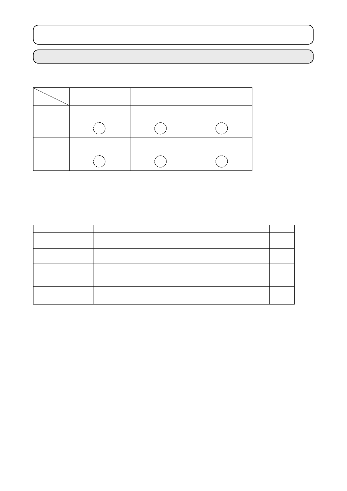
* 6 kinds of service patterns are contained in the media of the accessories.
Area
Kind
1306
2206
1510
2210
EHS,EHL
(Vinyl leather)
ø 30 Pitch 3.6mm
Pattern No. 61
ø 60 Pitch 3.6mm
Pattern No. 101
EHS,EHL
(Denim)
ø 30 Pitch 3 mm
Pattern No. 62
ø 60 Pitch 3 mm
Pattern No. 102
ø 30 Pitch 2.5 mm
ø 60 Pitch 2.5 mm
1) Kind of sewing data handled with IP-410 and the CP-20
Sewing data that each panel handles are as shown below.
Pattern name
Users' pattern
Vector format data
M3 data
Sewing standard
format
Description
Pattern that can be stored in the body.
Max. 200 patterns can be registered.
File that extension is ".VDT"
Read from media. Max. 999 patterns can be used.
Pattern data of AMS-210D series
Used by copying from floppy disk of AMS-210D series to
media. Max. 999 patterns can be used.
File that extension is ".DAT"
Read from media. Max. 999 patterns can be used.
ESS,ESL
Pattern No. 63
Pattern No. 103
IP-410
○
○
○
○
CP-20
○
○
×
×
2) Using the data (M3 data) of AMS-210D series with AMS-210E
There are two ways to use M3 data with AMS-210E.
Reading by using IP-410
1
Use PC (personal computer) and copy le (¥AMS¥AMS00xxx.M3) of M3 from oppy disk of AMS-D
to ¥AMS of media. Insert the media to IP-410, and select Pattern No.xxx from M3 data.
Changing to vector format data using PM-1
2
Change to the vector format data with PM-1. (For the details, refer to Help of PM-1.)
Copy the changed vector format data to ¥VDATA folder of the media.
Insert the media to IP-410 or CP-20 and select Pattern No.
– 25 –
Page 30

– 26 –
3) Folder structure of the media
Store each le in the directories below of the media.
Media drive
Store vector format data.
VDATA
AMS
Store M3 data.
SDATA
Store sewing standard
data.
VD00
VD00
AMS0
AMS0
SD00
SD00
.VDT
.VDT
. M3
. M3
. DAT
. DAT
Vectorformatdata:
Storein¥VDATA.
M3 data :
Store in ¥AMS.
Sewing standard
format :
Store in ¥SDATA.
Data that are not stored in the directories above cannot be read. So, be careful.
4) Inserting direction of the media
[IP-410]
T
urn the label side of the CompactFlash(TM)
1
to this side (place the notch of the edge to the
rear. ) and insert the part that has a small hole
into the panel.
Media
1. When the inserting direction is wrong, panel or media may be damaged.
2. Do not insert any item other than the CompactFlash(TM).
3. IP-410 corresponds to the CompactFlash(TM) of 2GB or less.
4. IP-410 corresponds to the format FAT16 of CompactFlash(TM). It does not correspond to
FAT32.
5. Be sure to use the CompactFlash(TM) which is formatted with IP-410. For the formatting
procedure of the CompactFlash(TM), see "@-2-26. Performing formatting of the media", p.83.
After completion of setting of the media, close the cover. By closing the cover, it is possible to ac-
2
cess. If the media and the cover come in contact with each other and the cover is not closed, check
the following matters.
Check that the media is securely pressed until it goes no further.
•
Check that the inserting direction of the media is proper.
•
Page 31

[CP-20]
Smart media
Insert the smart media in the direction as
1
shown in the gure.
After completion of setting of the smart media,
2
close the cover. By closing the cover, it is
possible to perform communication.
If the smart media and the cover come in
contact with each other and the cover is not
closed, check the following matters.
• Check that the inserting is stopped in the state that th
e smart media protrudes by approximately 10
mm.
• Check that the contact part is put downward and ins
erted.
• Check that the smart media other than 3.3 voltage type is used.
Be sure to use the smart media that has been formatted with IP-400.
For the formatting procedure of the smart media, refer to
@
-2-26. Performing formatting of the media" p.83
"
.
5) Removing procedure of the media
[IP-410]
Hold the panel by hand, open the cover, and press the
1
media removing lever. The media is eject.
When the lever is strongly pressed, the media
may be broken by protruding and falling.
When the media is drawn out as it is, removing is com-
2
pleted.
[CP-20]
Open the cover, push the smart media until it goes no further, and ease up force when it goes to the
1
end. The smart media returns by approximately 10 mm in the reverse order of the time of setting.
Then draw out the smart media to complete removing.
2
Cautions when using the media
• Do not wet or touch it with wet hands. Fire or electric shock will be caused.
• Do not bend, or apply strong force or shock to it.
• Never perform disassembling or remodeling of it.
• Do not put the metal to the contact part of it. Data may be disappeared.
• Avoid storing or using it in the places below.
Place of high temperature or humidity / Place of dew condensation /
Place with much dust / Place where static electricity or electrical noise is likely to occur
– 27 –
Page 32

– 28 –
2. WHEN USING IP-410
2-1. Name of each section of IP-410
1
2
(Front)
(Right side)
!0
6
9
8
7
4 5
3
Touch panel・LCD display section
1
2
READY key
Changeover of the data input screen and
→
the sewing screen can be performed.
INFORMATION key
3
Changeover of the data input screen and
→
the information screen can be performed.
COMMUNICATION key
4
Changeover of the data input screen and
→
the communication screen can be performed.
MODE key
5
the mode changeover screen which
Changeover of the data input screen and
→
performs various detail settings can be performed.
Media slot (Close the cover for use.)
6
Connector for RS-232C communication
7
Variable resistor for color LCD screen contrast adjust
8
Connector for external input
9
Media removing lever
!0
ment
Page 33

2-2. Buttons to be used in common
The buttons which perform common operations in each screen of IP-410 are as follows :
CANCEL button
In case of the data change screen, the data being
ENTER button
UP SCROLL button
DOWN SCROLL button
RESET button
NUMERAL INPUT button
CHARACTER INPUT button
→
RESSER LOWERING button
→
→
→
→
→
→
This button closes the pop-up screen.
→
changed can be cancelled.
This button determines the changed data.
This button scrolls the button or the display in the
upward direction.
This button scrolls the button or the display in the
downward direction.
This button performs the release of error.
This button displays ten keys and input of numerals
can be performed.
This button displays the character input screen.
Refer to
Presser is lowered, and the presser lowering screen
→
is displayed. To lift presser, press presser lift button
displayed in the presser lowering screen.
@
-2-14. Naming users' pattern” p.51
“
.
Bobbin winder button
Bobbin thread winding is performed.
→
Refer to
→
“@-2-11. Winding bobbin thread” p.46
.
– 29 –
Page 34

– 30 –
2-3. Basic operation of IP-410
Turn ON the power switch
1
When the power is turned ON rst, the language selection
screen is displayed. Set the language you use. (It is possible
to change with Memory switch U500.)
When ending the selection screen with CANCEL but-
A
B
ton
language selection, the language selection screen is
displayed whenever the power is turned ON.
Select the pattern No. you desire to sew.
2
or ENTER button without performing the
When the power is turned ON, the data input screen is dis-
played. Pattern No. button A whichs selected at present is
displayed in the center of the screen. Press the button to se-
lect the sewing shape. For selecting procedure of the sewing
shape, refer to "
@
-2-5. Performing sewing shape selection" p.36
When READY key B is pressed, the back color of LCD
display is changed to green, and the sewing machine is set to
the sewing possible state.
.
Page 35

Start sewing.
3
Start sewing referring to
"!-5-1. Sewing" p.22
.
* For the screen, refer to
the time of sewing shape selection" p.32 p.32
1. When using the exclusive presser, conrm the pattern shape for safety's sake. Should
the pattern protrude from the feeding frame, needle interferes with the feeding frame
during sewing, and there is a danger of needle breakage or the like.
2. When the presser is going up, be careful that your ngers are caught with the presser
since the presser moves after coming down.
3. When turning OFF the power without pressing READY key , the set value of
"Pattern No.", "X enlargement/reduction ratio", "Y enlargement/reduction ratio", "Max.
sewing speed", "Thread tension" or "Intermediate presser height" is not stored in
memory.
"@-2-4. LCD display section at
.
– 31 –
Page 36

– 32 –
2-4. LCD display section at the time of sewing shape selection
(1) Sewing shape data input screen
G
H
I
O
P
A
B C D E F
J
K
L
M
N
Q
Button and display
A
PATTERN BUTTON
NEW REGISTER button
B
USERS’ PATTERN
NEW REGISTER button
C
PATTERN BUTTON
NAME SETTING button
D
THREAD CLAMP button
E
INTERMEDIATE PRESSER
SETTING button
F
BOBBIN WINDER button
Description
Pattern button new register screen is displayed.
Refer to
/
Users’ pattern new register screen is displayed.
Refer to
/
Pattern button
Refer to
/
Effective/ineffective of thread clamp is selected.
: Thread clamp ineffective
: Thread clamp effective
Intermediate presser is lowered and the intermediate presser reference
value change screen is displayed.
Refer to
/
Bobbin thread can be wound.
Refer to
/
“@-2-15. Performing new register of pattern button” p.52
“@-2-13. Performing new register of users’ pattern” p.50
name input screen is displayed.
@
-2-14. Naming users’ pattern” p.51
“
@
-2-6. Changing item data” p.38
“
“@-2-11. Winding bobbin thread” p.46
.
.
.
.
.
Page 37

Button and display
SEWING SHAPE NO. display
G
Description
Kind and No. of the sewing shape being selected at present is displayed.
There are 4 kinds below of the kinds of sewing shape.
: Users' pattern
: Vector format data
: M3 data
: Sewing standard format
* Be sure to use the media that has been formatted with IP-410.
For the formatting procedure of the media, refer to
"@-2-26. Performing formatting of the media" p.83
.
SEWING SHAPE SELECTION
H
button
NEEDLE THREAD TENSION
I
SETTING button
X ACTUAL SIZE VALUE display
J
X SCALE RATE SETTING
K
button
Y ACTUAL SIZE VALUE display
L
Sewing shape being selected at present is displayed on this button and
when the button is pressed, the sewing shape selection screen is
displayed.
Refer to
/
Needle thread tension value which is set to the pattern data being selected
at present is displayed on this button and when the button is pressed, the
item data change screen is displayed.
Refer to “
/
Actual size value in X direction of sewing shape being selected at present
is displayed.
When the actual size value input is selected by setting memory switch
Refer to “
/
Scale rate in X direction of sewing shape being selected at present is
displayed on this button.
When the scale input is set to non-selection by setting memory switch
Refer to “
/
Actual size value in Y direction of sewing shape being selected at present
is displayed.
When the actual size value input is selected by setting memory switch
Refer to “
/
“@-2-5. Performing sewing shape selection”. p.36
@
-2-6. Changing item data”
, X actual size value setting button is displayed.
@
-2-6. Changing item data”
, the button goes out and the X scale is displayed.
@
-2-6. Changing item data”
, Y actual size value setting button is displayed.
@
-2-6. Changing item data”
.
p.38
.
p.38
.
p.38
.
p.38
M
Y SCALE RATE SETTING
button
N
MAX. SPEED LIMITATION
O
FOLDER NO. display
P
FOLDER SELECTION button
Q
PATTERN REGISTER button
Scale rate in Y direction of sewing shape being selected at present is
displayed on this button. When the scale input is set to non-selection by
setting memory switch , the button goes out and the Y scale is
displayed.
Maximum speed limitation which is set at present is displayed on this button
and when the button is pressed, the item data change screen is displayed.
(However, maximum speed limitation which is displayed is different from
the maximum number of revolutions in the pattern.)
Refer to “
/
Pattern register button which is displayed indicates the folder No. which has
been stored.
Folders to display the patterns are displayed in order.
PATTERN REGISTER but tons stored in O FOLDER NO display are
displayed.
Refer to “
/
* This button is not displayed in the initial state.
Refer to “
/
@
-2-6. Changing item data”. p.38
@
-2-15. Performing new register of pattern button”
@
-2-6. Changing item data”.
p.38
. p.52
– 33 –
Page 38

– 34 –
(2) Sewing screen
A B C D
E
F
G
H
I
J
K
L
O
N
P
M
Q
R
S
Button and display
A
PATTERN MOVE button
THREAD CLAMP button
B
C
IN T ER MED I ATE PRE S S ER
SETTING button
D
RETURN TO ORIGIN button
Description
Feeding frame is lowered and the pattern move screen is displayed.
Refer to
→
because of interruption of needle tip” p.45
Effective/ineffective of the thread clamp is selected.
: Thread clamp effective
Intermediate presser is lowered and the intermediate presser reference
value change screen is displayed.
Refer to
/
This button returns the presser to the start of sewing and raises the presser
at the time of temporary stop.
“@-2-10 . When sett ing of sewing p roduct is diff icult
.
: Thread clamp ineffective
“@-2-6.
Changing item data” p.38
.
Page 39

Button and display
E
SEWING SHAPE NO. display
Description
Kind and No. of the sewing shape being selected at present is displayed.
There are 4 kinds below of the kinds of sewing shape.
F
SEWING SHAPE display
G
NE E DLE T H READ TENSIO N
SETTING button
H
TOTAL NUMBER OF STITCHES
OF SEWING SHAPE display
I
COUNTER VALUE CHANGE
button
: Vector format data
: M3 data
: Sewing standard format
* Be sure to use the media that has been formatted with IP-410.
For the formatting procedure of the media, refer to
"@-2-26. Performing formatting of the media" p.83
Sewing shape being selected at present is displayed.
Needle thread tension value which is set to the pattern data being selected
at present is displayed on this button and when the button is pressed, the
item data change screen is displayed.
Refer to
/
Total number of stitches of the sewing shape being selected at present is
displayed.
* Displayed only when the sewing shape being selected is the standard
pattern.
Existing counter value is displayed on this button.
When the button is pressed, the counter value change screen is displayed.
Refer to
/
: Users' pattern
2-6. Changing item data” p.38p.38
“@-
2-12. Using counter” p.47p.47
“@-
.
.
.
J
COUNTER CHANGE OVER
button
K
STEP SEWING button
L
FOLDER NO. display
M
SPEED variable resistor
N
X SCALE RATE display
O
X ACTUAL SIZE VALUE display
P
Y ACTUAL SIZE VALUE display
Q
Y SCALE RATE display
R
MAX. SPEED LIMITATION
display
PATTERN REGISTER button
S
Display of sewing counter/No. of pcs. counter can be changed over.
Refer to
/
Step sewing screen is displayed. Checking of the pattern shape can be
performed.
Refer
/
Pattern register button which is displayed indicates the folder No. which has
been stored.
Number of rotations of the sewing machine can be changed.
Scale rate in X direction of sewing shape being selected is displayed.
Actual size value in X direction of sewing shape being selected is displayed.
Actual size value in Y direction of sewing shape being selected is displayed.
Scale rate in Y direction of sewing shape being selected is displayed.
Maximum speed limitation which is set at present is displayed. However,
the display is different from the maximum number of revolutions in the
pattern. However, the display is different from the maximum number of
revolutions in the pattern.
Pattern register buttons stored in L FOLDER NO. display are displayed.
Refer to
/
* This button is not displayed in the initial state.
2-12. Using counter” p.47p.47
“@-
2-7. Checking pattern shape” p.40p.40
“@-
@
“
-2-15. Performing new register of pattern button” p.52
.
.
.
– 35 –
Page 40

– 36 –
2-5. Performing sewing shape selection
Display the data input screen.
1
Only in case of the data input screen (blue), the selection of
sewing shape can be performed. In case of the sewing screen
A
(green), press READY key and display the data input
screen (blue).
Call the sewing shape selection screen.
2
Press SEWING SHAPE button
selection screen is displayed.
Select the sewing shape.
3
There are 4 kinds of the sewing shape.
Press SEWING SHAPE SELECTION button B.
* This button is not displayed in the initial state.
and the sewing shape
A
C
D
E
B
When button C or D is pressed in this screen,
X or Y enlarging/reducing ratio can be changed. For the
details, refer to
Determine the kind of sewing shape.
4
"@-2-6. Changing item data" p.38
There are 4 kinds below of the sewing shape. Select the kind
you desire from among them.
Maximum number of
patterns
200
999
999
999
F
Pictograph
Name
Users' pattern
Vector format data
M3 data
Sewing standard format
.
Be sure to use the media that has been formatted with IP-410.
For the formatting procedure of the media, refer to
"@-2-26. Performing formatting of the media" p. 83.
Select the sewing shape you desire from SEWING SHAPE SELECTION buttons
button.
F
and press ENTER
E
The sewing shape list screen corresponding to the kind of sewing shape you selected is displayed.
Page 41

Select the sewing shape.
5
When UP or DOWN SCROLL button G is pressed,
the SEWING SHAPE buttons H are changed over in order.
Here, press the SEWING SHAPE button you desire to select.
The details of the selected shape is displayed at the upper part
of the screen.
H
J
G
Determine the sewing shape.
6
When ENTER button I is pressed, the sewing shape is
K
I
determined and the data input screen is displayed.
When the sewing shape is users' pattern, the screen as A is
displayed.
A
PATTERN NO. SELECTION button J that is registered to
users' pattern is displayed. Press the button of PATTERN NO.
you desire to select.
In addition, when you desire to conrm the selected shape,
press VIEWER button K, and the viewer screen is dis-
played to display the selected shape.
– 37 –
Page 42

– 38 –
2-6. Changing item data
E
1
Display the data input screen.
In case of the data input screen, the change of item data
A
can be changed. In case of the sewing screen (green), press
B
READY switch to display the data input screen (blue).
* Thread tension value can be changed even in the sewing
C
D
screen.
Display the item data input screen.
2
When the button of the item data you desire to change is
pressed, the item data input screen is displayed.
Item data are 5 items below.
Item range
Scale rate in X direction
A
Scale rate in Y direction
B
Thread tension
C
Max. speed limitation
D
E
Intermediate presser heigh
t
0.0 to 3.5 (mm) (Max 0.0 to 7.0 (mm))
Input range
1.0 to 400.0 (%)
1.0 to 400.0 (%)
0 to 200
400 to 2,700 (rpm)
Initial value
100.0 (%)
100.0 (%)
Pattern set value
2,700 (rpm)
Pattern set value
* Thread tension value and intermediate presser reference value will change with every pattern to be
selected.
* A Scale rate in X direction and B Scale rate in Y direction can be changed to actual size value
input by selection of the memory switch .
For enlargement and reduction, there are two ways. The data already read in can enlarge or reduce
repeatedly with this button. When you desire to enlarge or reduce again from the original data, see
"@-2-5. Performing sewing shape selection" p.36
.
* In case of the point sewing, even when increase/decrease of number of stitches is set under
Enlargement and reduction function mode, enlargement and reduction can be performed with in-
crease/decrease of pitch.
* When X/Y scale rate is individually set in case of circle or arc, or X/Y enlargement and reduction
are repeated, the sewing is changed to point sewing and the shape may not be kept. Enlargement
and reduction can be performed by increase/decrease of pitch. In this case, set and read X/Y scale
rate in the pattern list screen.
* Max. input range and initial value of max. speed limitation D are determined with memory switch
.
* Change of the intermediate presser height cannot be performed immediately after turning ON the
power. Use the machine after pressing READY key and performing the origin retrieval.
The setting exceeding 100% is dangerous since needle and the cloth presser interferes
with each other and needle breakage or the like will occur.
Page 43

For example, input X scale rate.
Press A to display the item data input screen.
Input the data.
F
3
Input the value you desire with ten keys and + / – keys F.
Determine the data.
4
When ENTER button G is pressed, the data is deter-
mined.
* For the other item data, the data can be changed by the same
G
operation.
* It is possible to input X/Y value of enlargement/reduction ratio
and actual size value with one screen.
1. When turning OFF the power without pressing READY key , the set value of
"Pattern No.", "X enlargement/reduction ratio", "Y enlargement/reduction ratio", "Max.
sewing speed", "Thread tension" or "Intermediate presser height" is not stored in
memory.
2. In case thread tension is changed in the read state, the set value when the power is
turned OFF without pressing READY key or without performing sewing is not stored
in memory.
3. When operation processing cannot be performed since the reduction ratio is excessively small, E045 Pattern data error is displayed.
4. When the scale rate is changed with increase/decrease of number of stitches (pitch is
xed), mechanical control command inputted to the points other than the shape point
is deleted.
H
When X/Y enlargement/reduction ratio, thread tension, intermedi-
ate presser, adding/deleting of thread tension command, or adding/
deleting of increase/decrease value of intermediate presser of us-
ers’ pattern or media pattern is performed, the pattern kind section
becomes change display
In case of change display
.
H
, the change conrmation screen is
H
displayed at the time of the change of pattern.
When ENTER button I is pressed, the information on the
current pattern is invalidated and the pattern No. is changed.
To store the changed pattern, refer to
register of users’ pattern” p.50
“@-2-13. Performing new
.
I
– 39 –
Page 44

– 40 –
2-7. Checking pattern shape
WARNING :
Make sure without fail of the contour of the sewing pattern after selection of the sewing pattern.
If the sewing pattern extends outside the work clamp feet, the needle will interfere with the work
clamp.
A
Display the sewing screen.
1
Display the data input screen (blue) and press READY key
A. Then the back-light of LCD changes to green and
sewing is possible.
Display the step sewing screen.
2
When STEP SEWING button B is pressed, the step
B
sewing screen is displayed.
Lower the presser with the foot switch.
3
The sewing machine does not start even when the
foot switch is depressed with this mode.
Proceed stitching with the presser lowered.
4
Check the shape with PRESSER BACK button
PRESSER FORWARD button
held pressed for a xed period of time, the presser continues
E
to move even when the button is detached.
When you desire to stop, press STOP button
When RETURN TO ORIGIN button
presser moves to the origin.
.
When the button is
D
is pressed, the
F
G
C
.
and
C
D
F
G
Finish checking the shape.
5
When CANCEL button
E is pressed, the screen returns
to the sewing screen. When the checking of the shape is
not in the position of the start of sewing or that of the end of
sewing, press the foot switch. Then it is possible to sew from
the midway of checking.
The presser does not come down immediately after
turning ON the power.
Page 45

2-8. Performing modication of needle entry point
Thread tension value and intermediate presser height of the needle
entry point can be changed.
(1) Changing the thread tension value
A
Press THREAD TENSION button A in the sewing
screen to display the thread tension setting screen.
Press THREAD TENSION SELECTION button
display the thread tension command selection screen.
B
B
to
C
D
F
J
When C is pressed, the thread tension value increase/
decrease input screen is displayed.
With D or E, needle moves by one stitch in front
or rear in the state that the presser is lowered.
With F or G the needle moves to the needle
e
ntry point where there is the thread tension command in the
E
I
H
G
front or rear.
When you desire to stop, press STOP button H.
When RETURN TO ORIGIN button
is pressed, the
I
presser moves to the origin.
The value which is displayed is the absolute value (thread
tension value + thread tension command value).
Input the value you desire with TEN keys and +/– keys J.
When ENTER button K is pressed, the data is deter-
mined.
When checking the needle, or performing the feed
forward or backward, the machine fails to work unless the presser is lowered. Use the machine after
K
lowering the presser.
– 41 –
Page 46

– 42 –
A
(2) Changing the intermediate presser height value
Press INTERMEDIATE PRESSER button
in the
A
sewing screen to display the intermediate presser foot height
reference value setting screen.
Press INTERMEDIATE PRESSER SELECTION button
to display the intermediate presser height increase/de-
B
crease value selection screen.
When C is pressed, the intermediate presser height
B
increase/decrease value selection screen is displayed.
C
D
F
J
With D or E, needle moves by one stitch in front
or rear in the state that the presser is lowered.
With
F
or
, needle moves to the needle entry
G
point where there is the intermediate presser command in front
or rear.
When you desire to stop, press STOP button
H
When RETURN TO ORIGIN button I is pressed, the
presser moves to the origin. The value which is displayed is
E
I
H
G
the absolute value (intermediate presser height value + inter-
mediate presser increase/decrease value).
Input the value you desire with TEN keys and +/– keys J.
When ENTER button K is pressed, the data is deter-
mined.
1. When checking the needle, or performing the feed
forward or backward, the machine fails to work
unless the presser is lowered. Use the machine
after lowering the presser.
2. When increasing the height of intermediate press-
er or making the needle size thicker, conrm the
clearance between the wiper and the components.
Wiper cannot be used unless the clearance is se-
cured. In this case, turn OFF the wiper switch, or
K
change the set value of memory switch U105.
.
Page 47

2-9. How to use temporary stop
When TEMPORARY STOP switch 1 is pressed
during sewing, the sewing machine can be
stopped. At this time, the error screen is displayed
to inform that the stop switch has been pressed.
1
(1) To continue performing sewing from some point in sewing
Release the error.
1
G
Press RESET button
Perform thread trimming.
2
Press THREAD TRIM button
A to release the error.
B to perform thread
trimming.
A
When PRESSER UP button
G is pressed, the presser
goes up. Turn OFF the power since the operation afterwards
cannot be performed.
When thread trimming is performed, INTERMEDIATE
PRESSER UP/DOWN button
button
, FEED FORWARD button
D
RETURN TO ORIGIN button
, FEED BACKWARD
C
are displayed in the
F
screen.
1. When the presser is raised and the operation is
B
stopped on the way because of the trouble of for-
getting to enter the bobbin case or the like, press
E
, and
D
PRESSER UP button G and turn OFF the
power.
2. PRESSER UP button G is not displayed
when the presser is of pneumatic type.
Adjust the presser to the re-sewing position.
3
When FEED BACK button
returns stitch by stitch and when FEED FORWARD button
is pressed, it advances stitch by stitch. Move the presser to the
C
E
F
E
re-sewing position.
Re-start the sewing
4
When the pedal is depressed, sewing starts again.
– 43 –
is pressed, the presser
D
Page 48

– 44 –
(2) To perform re-sewing from the start
Release the error.
1
G
Press RESET button
Perform thread trimming.
2
Press THREAD TRIM button
A to release the error.
B to perform thread trim-
ming.
When PRESSER UP button
A
goes up. Turn OFF the power since the operation afterwards
G is pressed, the presser
cannot be performed.
When thread trimming is performed, INTERMEDIATE
PRESSER UP/DOWN button
button
, FEED FORWARD button
D
RETURN TO ORIGIN button
, FEED BACKWARD
C
E
are displayed in the
F
screen.
1. When the presser is raised and the operation is
B
stopped on the way because of the trouble of for-
getting to enter the bobbin case or the like, press
, and
D
PRESSER UP button
power.
2. PRESSER UP
when the presser is of pneumatic type.
Return to the origin.
3
When RETURN T
O ORIGIN button
button G is not displayed
G and turn OFF the
pop-up is closed, the sewing screen is displayed and the ma-
chine returns to the position of the start of sewing.
C
Perform again the sewing work from the start.
4
E
When the pedal is depressed, sewing starts again.
F
F is pressed, the
Page 49

2-10. When setting of sewing product is difcult because of interruption of needle tip
A
Display the pattern button move screen.
1
When PATTERN BUTTON MOVE button A is pressed,
the pattern button move screen is displayed.
Move the pattern.
2
Lower the presser, and input the move direction with DIREC-
TION key B.
B
– 45 –
Page 50

2-11. Winding bobbin thread
(1) When performing winding bobbin thread while performing sewing
Thread the bobbin winder and wind the bobbin
thread onto the bobbin as illustrated in the gure.
(2) When performing winding bobbin thread only
Display the bobbin winding screen.
1
Press BOBBIN WINDER button A in the data input
A
screen (blue) and the bobbin winding screen is displayed.
Start bobbin winding.
2
Depress the start pedal, and the sewing machine rotates and
B
starts winding bobbin thread.
Stop the sewing machine.
3
Press STOP button B and the sewing machine stops
and returns to the normal mode. Or, depress the start pedal
again during winding bobbin and the sewing machine stops
while the bobbin thread winding mode stays as it is. Depress
the start pedal again and the bobbin winding starts again. Use
this way when winding bobbin thread around plural bobbins.
Bobbin winder does not work immediately after turning ON the power. Perform the bob-
bin winding after setting pattern No. or the like once, pressing the READY key ,
and making the sewing LED light up.
– 46 –
Page 51

2-12. Using counter
(1) Setting procedure of the counter
Display the counter setting screen.
1
A
B
C
Press
is displayed on the
A
switch and the COUNTER SETTING button
screen. When this button is pressed, the
counter setting screen is displayed.
Selection of kinds of counters
2
This sewing machine has two kinds of counters, i. e. , sewing
counter and No. of pcs. counter
KIND SELECTION button
LECTION button
C to display the counter kind selection
. Press SEWING COUNTER
B or NO. OF PCS. KIND SE-
screen. The kinds of the respective counters can be set sepa-
rately.
[ Sewing counter ]
UP counter :
Every time the sewing of one shape is performed, the existing
value is counted up. When the existing value is equal to the set
value, the count-up screen is displayed.
DOWN counter :
Every time the sewing of one shape is performed, the existing
value is counted down. When the existing value is reached to “0”,
the count-up screen is displayed.
[ No. of pcs. Counter ]
UP counter :
Every time one combination sewing is performed, the existing
value is counted up. When the existing value is equal to the set
value, the count-up screen is displayed.
DOWN counter :
Every time one combination sewing is performed, the existing
value is counted down. When the existing value is reached to “0”,
the count-up screen is displayed.
– 47 –
Page 52

– 48 –
Change of counter set value
3
D
E
In case of the sewing counter, press button
case of the No. of pcs. counter, press button
D and in
E and the
set value input screen is displayed.
Here, input the set value.
When “0” is inputted in the set value, the display of count-up
screen is not performed.
F
G
Change of counter existing value
4
In case of the sewing counter, press button
case of the No. of pcs. counter
, press button
existing value input screen is displayed.
Here, input the existing value.
F and in
and the
G
Page 53

(2) Count-up releasing procedure
When the count-up condition is reached during sewing work, the
count-up screen is displayed and the buzzer beeps. Press CLEAR
to reset the counter and the screen returns to the
button
A
sewing screen. Then the counter starts counting again.
A
(3) How to change the counter value during sewing
A
Display the counter value change screen.
1
When you desire to revise the counter value during sewing
work due to the mistake or the like, press COUNTER VALUE
CHANGE button
A on the sewing screen. The counter
value change screen is displayed.
Change the counter value.
2
Input the value you desire with ten keys, or “+” or “–” key B.
Determine the counter value.
3
D
When ENTER button C is pressed, the data is deter-
B
mined.
When you desire to clear the counter value, press CLEAR but-
C
ton
D.
– 49 –
Page 54

– 50 –
2-13. Performing new register of users’ pattern
Display the data input screen.
1
Only in case of the data input screen (blue), new register of the
pattern can be performed. In case of the sewing screen (green),
A
press READY switch
and display the data input screen
(blue).
Call the new register of users’ pattern screen.
2
Press NEW REGISTER button
A and the new register
of users’ pattern screen is displayed.
Input the users’ pattern No.
3
Input the users’ pattern No. you desire to newly register with
the ten keys B. It is possible to retrieve the users’ pattern No.
B
D
C
which has not been registered with the + or – button
E
(C and D).
Determine the users’ pattern No.
4
Press ENTER button
E to determine the users’ pattern
NO. to be newly registered and the data input screen at the
time of users’ pattern selection is displayed.
When the existing users' pattern No. is inputted and ENTER
button is pressed, the overwriting conrmation screen is dis-
played.
Page 55

2-14. Naming users’ pattern
As many as 14 characters can be inputted in each users' pattern.
A
Display the data input screen.
1
Only in case of the data input screen (blue) at the time of pat-
tern button selection, it is possible to input the name of pattern
button. In case of the sewing screen (green), press READY
switch to display the data input screen (blue).
Call the character input screen.
2
When CHARACTER INPUT button A is pressed, the
character input screen is displayed.
Input the character.
3
Press CHARACTER button B you desire to input and the
F
input of character can be performed.
As many as 14 characters of characters ( to and
B
C
D
E
to ) and symbols ( , , , , and ) can be
inputted. The cursor can be moved with CURSOR LEFT
TRAVEL button
and CURSOR RIGHT TRAVEL button
C
D. When you desire to delete the inputted character,
adjust the cursor to the position of the character you desire to
delete and press DELETE button
Finish the input of character.
4
E
.
When ENTER button F is pressed, the input of
character is nished. After the nish, the inputted character is
displayed on the upper part of the data input screen (blue).
– 51 –
Page 56

– 52 –
2-15. Performing new register of pattern button
E
A
Display the data input screen.
1
Only in case of the data input screen (blue), new register of the
pattern button can be performed. In case of the sewing screen
(green), press READY switch and display the data input
screen (blue).
Call the new register of pattern button screen.
2
Press NEW REGISTER button A and the new
of pattern button screen is displayed.
Input the pattern button No.
3
Input the pattern button No. you desire to newly register with
the ten keys B. New register to the pattern button No. which
has been already registered is prohibited.
F
It is possible to retrieve the pattern button No. which has not
register
B
been registered with the “+” or “–” button (
Select the folder to be stored.
4
and D).
C
It is possible for the pattern buttons to be stored in ve folders.
As many as 10 pattern buttons can be stored for one folder.
D
C
The folder to store the button can be selected with FOLDER
SELECTION button E.
Determine the pattern No.
5
Press ENTER button
to determine the pattern button
F
No. to be newly registered and the data input screen at the
time of pattern button selection is displayed.
Press P1 to P50 key while the sewing screen is displayed or the sewing LED lights up
and the presser comes down. Be careful that your ngers are not caught in the presser.
Page 57

2-16. LCD display section at the time of pattern button selection
(1) Pattern button data input screen
C
E
G
F
J
H
I
K
S
T
U
A B D
W
M
N
O
P
Q
R
L
V
Button and display
PATTERN BUTTON
A
COPY button
PATTERN BUTTON
B
NAME SETTING button
C
PATTERN BUTTON
NAME display
WINDING BOBBIN button
D
PATTERN BUTTON
E
NO. display
SEWING SHAPE
F
Description
Pattern button copy screen is displayed.
Refer to
/
Pattern button name input screen is displayed.
Refer to
/
2-14. Naming users’ pattern” p.51
“@-
Character which is registered to the pattern button No. being selected is
displayed.
Bobbin thread can be wound.
Refer to
/
Pattern button No. being selected at present is displayed on this button
and when the button is pressed, the pattern button No. selection screen is
displayed.
Refer to
/
Sewing shape which is registered to the pattern button No. being selected
is displayed.
@
-2-19. Copying pattern button” p.60
“
.
“@-2-11. Winding bobbin thread” p.46
@
-2-17. Performing pattern button No. selection” p.57
“
.
.
.
– 53 –
Page 58

– 54 –
Button and display
SEWING SHAPE NO.
G
Description
Sewing shape which is registered to the pattern button No. being selected
is displayed. There are 4 kinds below of the kinds of sewing shape.
: Users' pattern
: Vector format data
: M3 data
: Sewing standard format
* Be sure to use the media that has been formatted with IP-410.
For the formatting procedure of the media, refer to
@
"
-2-26. Performing formatting of the media" p.83.
TOTAL NO. OF STITCHES
H
2-STEP STROKE display
I
THREAD TENSION display
J
TRAVEL AMOUNT IN X
K
DIRECTION display
TRAVEL AMOUNT IN Y
L
DIRECTION display
X ACTUAL SIZE VALUE display
M
X SCALE RATE display
N
Y ACTUAL SIZE VALUE display
O
Y SCALE RATE display
P
Total number of stitches of the pattern which is registered to the pattern
button No. being selected is displayed.
* This item is displayed only when the sewing shape being selected is the
standard pattern.
2-step stroke value registered to the pattern button No. being selected is
displayed.
Thread tension value which is registered to the pattern button No. being
selected is displayed.
Travel amount in X direction which is registered to the pattern button No.
being selected is displayed.
Travel amount in Y direction which is registered to the pattern button No.
being selected is displayed.
X actual size value which is registered to the pattern button No. being
selected is displayed.
X scale rate which is registered to the pattern button No. being selected is
displayed.
Y actual size value which is registered to the pattern button No. being
selected is displayed.
Y scale rate which is registered to the pattern button No. being selected is
displayed.
MAX. SPEED LIMITATION
Q
PATTERN BUTTON EDIT button
R
FOLDER NO. display
S
FOLDER SELECTION button
T
SEWING SHAPE SELECTION
U
DATA INPUT SCREEN DISPLAY
button
PATTERN button
V
PRESSER DOWN button
W
Maximum speed limitation which is registered to the pattern button No.
being selected is displayed.
Pattern button edit screen is displayed.
Folder No. in which the displayed pattern buttons are stored is displayed.
Folders to display the pattern button are displayed in order.
Sewing shape data input screen is displayed.
Refer to
/
Pattern buttons stored in S Folder No. are displayed.
Refer to
/
Presser can be lowered and the presser down screen is displayed.
To raise the presser, press the presser up button which is displayed in the
presser down screen.
@
-2-4.(1) Sewing shape data input screen” p.32
“
“@-2-15. Performing new register of pattern button” p.52.
.
Page 59

(2) Sewing screen
H
J
I
N
M
P
Q
O
R
S
B
F GE
D
C
K
L
T
U
V
A
W
Button and display
2-STEP STROKE display
A
PATTERN BUTTON NAME
B
display
X SCALE RATE display
C
X ACTUAL SIZE VALUE display
D
THREAD CLAMP button
E
Description
2-step stroke value registered to the pattern button No. during sewing is
displayed.
Character which is registered to the pattern button No.
being sewn is displayed.
Scale rate in X direction which is registered to the pattern button No. being
sewn is displayed.
Actual size value in X direction which is registered to the pattern button No.
being sewn is displayed.
Effective/ineffective of thread clamp is selected.
: Thread clamp ineffective
: Thread clamp effective
– 55 –
Page 60

– 56 –
Button and display
PRESSER DOWN button
F
Description
Presser can be lowered and the presser down screen is displayed.
To raise the presser, press the presser up button displayed in the presser
down screen.
RETURN TO ORIGIN button
G
PATTERN NO. display
H
SEWING SHAPE display
I
SEWING SHAPE NO. display
J
Y ACTUAL SIZE VALUE display
K
Y SCALE RATE display
L
TOTAL NO. OF STITCHES OF
M
SEWING SHAPE display
NEEDLE THREAD TENSION
N
SETTING button
TRAVEL AMOUNT IN X
O
DIRECTION display
Presser is returned to the start of sewing and is raised at the time of
temporary stop.
Pattern button No. being sewn is displayed.
Sewing shape being sewn is displayed.
Kind of sewing and sewing shape No. which are registered to the pattern
being sewn are displayed.
Actual size value in Y direction which is registered to the pattern button No.
being sewn is displayed.
Scale rate in Y direction which is registered to the pattern button No. being
sewn is displayed.
Total number of stitches of sewing shape which is registered to the pattern
button No. being sewn is displayed.
Needle thread tension value which is set to the pattern data being selected
at present is displayed on this button and when the button is pressed, the
item data change screen is displayed.
Refer to.
/
Travel amount in X direction which is registered to the pattern button No.
being sewn is displayed.
@
-2-6. Changing item data” p.38
“
.
COUNTER VALUE CHANGE
P
button
COUNTER CHANGEOVER
Q
button
STEP SEWING button
R
FOLDER NO. display
S
SPEED variable resistor
T
MAX. SPEED LIMITATION
U
display
TRAVEL AMOUNT IN Y
V
DIRECTION display
PATTERN REGISTER button
W
Existing counter value is displayed on this button. When the button is
pressed, the counter value change screen is displayed.
Refer to
/
Display of sewing counter/No. of pcs. counter can be changed over.
Refer to
/
The step sewing screen is displayed. Checking the pattern shape can be
performed.
Refer to
/
Folder No. in which the displayed pattern register buttons are stored is
displayed.
Number of revolutions of the sewing machine can be changed.
Maximum speed limitation which is registered to the pattern button No.
being sewn is displayed.
Travel amount in Y direction which is registered to the pattern button No.
being sewn is displayed.
Pattern button which is stored in S FOLDER NO. is displayed.
Refer to
/
@
-2-12. Using counter” p.47
“
@
-2-12. Using counter” p.47
“
@
-2-7. Checking pattern shape” p.40
“
“@-2-15. Performing new register of pattern button”
.
.
.
.
p.52
Page 61

2-17. Performing pattern button No. selection
(1) Selection from the data input screen
Display the data input screen.
1
A
In case of the data input screen (blue), it is possible to select
the pattern button No. In case of the sewing screen (green),
press READY switch to display the data input screen.
Call the pattern button No. selection screen.
2
F
C
When PATTERN BUTTON NO. SELECTION button
is pressed, the pattern button No. selection screen is dis-
played. Pattern button No. which is selected at present and the
contents are displayed on the upper part of the screen, and the
list of the pattern button No. buttons which have been regis-
tered is displayed on the lower part of the screen.
Select the pattern button No.
3
When UP or DOWN SCROLL button B is pressed,
which have been registered are
C
D
pattern button No. buttons
changed over in order. The contents of sewing data which
have been inputted in the pattern button No. are displayed in
the button. Here, press the pattern button No. button C you
B
desire to select.
E
Determine the pattern button No.
4
A
When ENTER button D is pressed, the pattern button
No. selection screen is closed and the selection is nished.
However, the pattern buttons which are registered to the com-
bination sewing cannot be deleted.
* When you desire to delete the pattern button which has been
registered, press DELETE
button. However, the pat-
E
tern buttons which are registered to the combination sewing
cannot be deleted.
* For the pattern No. to be displayed, press FOLDER SELEC-
TION
F button and pattern button Nos. which have been
stored in the specied folder are displayed in the list. When the
folder No. is not displayed, all pattern Nos. which have been
registered are displayed.
– 57 –
Page 62

– 58 –
(2) Selection by means of the shortcut button
WARNING :
Make sure without fail of the contour of the sewing pattern after selection of the sewing pattern.
If the sewing pattern extends outside the work clamp feet, the needle will interfere with the work
clamp.
Display the data input screen or the sewing screen.
1
When the pattern is registered to the folder, pattern buttons A
are surely displayed on the lower side of the screen of the data
input screen or sewing screen.
Select the pattern No.
2
Pattern button is displayed with every folder which is specied
when the pattern is newly created.
B
When FOLDER SELECTION button
pattern button to be displayed is changed. Display and press
A
the button of the pattern button No. you desire to sew. When it
is pressed, the pattern button No. is selected.
is pressed, the
B
Page 63

2-18. Changing contents of pattern button
Display the data input screen at the time of pattern button
1
selection.
Only in case of the data input screen (blue) at the time of pat-
tern selection, it is possible to change the contents of pattern.
In case of the sewing screen (green), press READY
switch
I
H
D
L
F
K
A
to display the data input screen at the time of pattern
button selection.
Display the pattern button data change screen.
2
When P
ATTERN BUTTON DATA CHANGE button
pressed, the pattern button data change screen is displayed.
Display the input screen of the item data you desi
3
change.
J
Data that can be changed are 11 items below.
B
C
E
G
Scale rate in X direction
B
Scale rate in Y direction
C
Thread tension 0 to 200
D
Max. speed limitation 400 to 2700(rpm) 2700
E
Travel amount in X
F
direction
Travel amount in Y
G
direction
Sewing shape - -
H
Folder No. 1 to 5 -
I
Intermediate presser
J
Thread clamp With/without With
K
2-step stroke height 50 to 90 70
L
Item Input range Initial value
1.0 to 400.0(%) 100.0
1.0 to 400.0(%) 100.0
1306:–66.0 to +66.0 (mm)
1510:–76.0 to +76.0(mm)
2206:–111.0 to +111.0(mm)
2210:–111.0 to +111.0(mm)
1306:–33.0 to +33.0(mm)
1510:–51.0 to +51.0(mm)
2206:–33.0 to +33.0(mm)
2210:–51.0 to +51.0(mm)
0.0 to 3.5 (mm)
(Max. 0.0 to 7.0 (mm))
re to
Pattern set
0.0
0.0
Pattern set
A
value
value
is
When pressing each button of B through H and J, the item data input screen is displayed. When the
buttons of
and K are pressed, Folder Nos. and With/without thread clamp are changed over
I
.
* Thread tension value and intermediate presser reference value will change with every pattern to be
selected.
* B Scale rate in X direction and C Scale rate in
input by selection of memory switch
Y direction can be changed to the actual size value
.
* Max. input range and initial value of max. speed limitation D are determined with memory switch
.
* The input range of travel amount in X direction F and travel amount in Y direction G differs accord-
ing to the sewing range.
– 59 –
Page 64

– 60 –
Determine the change of item data
4
For example, input X scale rate. Press
B to display
K
ten keys or + or – key K. When ENTER button
pressed, the data is determined.
the item data input screen. Input the value you desire with the
L
Close the pattern button data change screen.
5
M
When the change is over
, press CLOSE button
The pattern button data change screen is closed and the
screen returns to the data input screen.
* It can be performed to change the other item data b
operation.
In case thread tension is changed in the read state,
the set value when the power is turned OFF without
L is
M.
y the same
pressing READY key or without performing
sewing is not stored in memory.
2-19. Copying pattern button
The sewing data of the pattern button No. which has already been registered can be copied to the pat-
tern button No. which is not registered. Overwriting copy of the pattern button is prohibited. When you
desire to overwrite, perform it after deleting the pattern button once.
Refer to
/
“@-2-17. Performing pattern button No. selection” p.57
A
Display the data input screen.
1
Only in case of the data input screen (blue) at the ti
tern button selection, it is possible to copy
ing screen (green), press READY switch
data input screen (blue).
.
me of pat-
. In case of the sew-
to display the
Call the pattern copy screen.
2
When PA
TTERN BUTTON COPY button
A is pressed,
the pattern button copy (copy source selection) screen is dis-
played.
Page 65

Select the pattern No. of copy source.
3
Select the pattern button No. of copy source from the pattern
button list button B.
B
D
G
Next, press COPY DESTINATION INPUT button
the copy destination input screen is displayed.
C
Input the pattern No. of copy destination.
4
Input the pattern button No. of copy destination with ten keys D.
Pattern button No. which is not used yet can be retrieved with
– and + buttons (E and F).
In addition, the folder to be stored can be selected with FOLD-
.
ER SELECTION button
Start copying.
5
G
When ENTER button H is pressed, copying starts. The
copied pattern button No. in the selection state returns to the
pattern button copy (copy source selection) screen after ap-
H
proximately two seconds.
* Combination data can be copied in the same way.
C
and
F
E
2-20. Changing sewing mode
A
Select the sewing mode.
1
When switch is pressed in the state that the pattern has
been registered, SEWING MODE SELECTION button
is displayed on the screen. When this button is pressed, the
A
sewing mode changes alternately the individual sewing and
the combination sewing. (The mode cannot be changed even
when the button is pressed unless the pattern button is regis-
tered.)
* The image of the button of sewing mode selection button
changes according to the sewing mode which is selected at
present.
When individual sewing is selected :
When combination sewing is selected :
– 61 –
Page 66

– 62 –
2-21. LCD display section at the time of combination sewing
The sewing machine is capable of sewing in order by combining the plural pattern data. As many as 30
patterns can be inputted. Use this function when sewing plural different shapes on the sewing product.
In addition, it is possible to register as many as 20 of the combination sewing data. Use this function for
new creation and copying in case of need.
Refer to
/
and
(1) Pattern input screen
“@-2-15. Performing new register of pattern button” p.52
@
-2-19. Copying pattern button” p.60
“
.
A B C E F
G
H
I
D
J
Button and display
COMBINATION DATA
A
NEW REGISTER button
COMBINATION DATA C O P Y
B
button
COMBI N AT I O N D ATA NA M E
C
INPUT button
COMBI N AT I O N D ATA NA M E
D
display
PRESSER DOWN button
E
BOBBIN WINDING
F
Description
Combination data No. new register screen is displayed.
Refer to
/
Combination pattern No. copy screen is displayed.
Refer to
/
Combination data name input screen is displayed.
Refer to
/
Name which is inputted in the combination data being selected is displayed.
Presser can be lowered and the presser down screen is displayed. To raise
the presser, press the presser up button displayed in the presser down
screen.
Bobbin thread can be wound.
Refer to
/
“@-2
-15. Performing new register of pattern button” p.52
@
-2-19. Copying pattern button” p.60
“
@
-2-14. Naming users’ pattern” p.51
“
“@-2-11. Winding bobbin thread” p.46
.
.
.
Page 67

Button and display Description
COMBINATION DATA NO.
G
SELECTION button
SEWING ORDER display
H
PATTERN SELECTION button
I
NEXT PAGE DISPLAY button
J
Combination data No. being selected is displayed in the button. When the
button is pressed, the combination data No. selection screen is displayed.
Sewing order of the inputted pattern data is displayed. When the screen
is changed over to the sewing screen, the pattern which is sewn first is
displayed in blue color.
Pattern No., shape, number of stitches, etc. which are registered in
SEWING ORDER are displayed on the button.
When the button is pressed, the pattern selection screen is displayed.
When the patterns which are registered to the combination data become
more than 6 pcs. , this button is displayed. It is possible to register the
patterns from the 7th to the next page. As many as 5 pages can be
displayed
* As many as the number of inputted patterns is displayed in
H
and
, display and button.
I
H
– 63 –
Page 68

– 64 –
(2) Sewing screen
B C D
E
F
K
I
H
J
G
L
M
N
O
P
X
A
Q
R
T
S
U
V
W
Y
Button and display
COMBINATION DATA NAME
A
display
THREAD CLAMP button
B
PRESSER DOWN button
C
RETURN TO ORIGIN button
D
COMBINATION DATA NO. display
E
PATTERN BUTTON NO. display
F
SEWING SHAPE display
G
Description
Name which is inputted in the combination data being selected is displayed.
Effective/ineffective of thread clamp is selected.
: Thread clamp ineffective
: Thread clamp effective
Presser can be lowered and the presser down screen is displayed.
To raise the presser, press the presser up button displayed in the presser
down screen.
Presser can be returned to the start of sewing and is raised at the time of
temporary stop.
Combination data No. being selected is displayed.
Pattern button No. being sewn is displayed.
Sewing shape which is registered to pattern button No. being sewn is
displayed.
SE W IN G OR DER RE T UR N
H
button
SEWING ORDER display
I
Pattern to be sewn can be returned by one.
Sewing order being sewn at present is displayed.
Page 69

Button and display
SEWING ORDER ADVANCE
J
button
Description
Pattern to be sewn can be advanced by one.
TOTAL NUMBER OF
K
REGISTERS display
TOTAL NUMBER OF STITCHES
L
display
THREAD TENSION display
M
TRAVEL AMOUNT IN X
N
DIRECTION display
COUNTER VALUE CHANGE
O
button
COUNTER CHANGEOVER
P
button
X ACTUAL SIZE AMOUNT
Q
display
X SCALE RATE display
R
S
SPEED variable resistor
Total number of patterns which is registered to combination No. being sewn
is displayed.
Total number of stitches of sewing shape being sewn is
Thread tension value which is registered to pattern button No. being sewn
is displayed.
Travel amount in X direction which is registered to the pattern button No.
being sewn is displayed.
Existing counter value is displayed on this button. When the button is
pressed, the counter value change screen is displayed.
Refer to
/
Display of sewing counter/No. of pcs. counter can be changed over.
Refer to
/
X actual size value of the sewing shape which is registered to pattern
button No. being sewn is displayed.
X scale rate of the sewing shape which is registered to
pattern button No. being sewn is displayed.
Number of revolutions of the sewing machine can be changed.
@
-2-12. Using counter” p.47
“
@
-2-12. Using counter” p.47
“
.
.
displayed.
T
Y ACTUAL SIZE VALUE display
U
Y SCALE RATE display
V
MAX. SPEED LIMITATION
display
TRAVEL AMOUNT IN Y
W
DIRECTION display
STEP SEWING button
X
2-STEP STROKE display
Y
Y actual size value of the sewing shape which is registered to pattern
button No. being sewn is displayed.
Y scale rate of the sewing shape which is registered to pattern button No.
being sewn is displayed.
Maximum speed limitation which is registered to pattern button No. being
sewn is displayed.
Travel amount in Y direction which is registered to the pattern button No.
being sewn is displayed.
The step sewing screen is displayed. Checking the
pattern shape can be performed.
Refer to
/
2-step stroke value registered to the pattern button No. during sewing is
displayed.
“@-2-7
Checking pattern shape” p.40
.
.
– 65 –
Page 70

2-22. Performing combination sewing
First, change the sewing mode to the combination sewing before performing setting.
Refer to
/
@
-2-20. Changing sewing mode” p.61
“
(1) Selection of combination data
A
Display the data input screen.
1
Only in case of the data input screen (pink), it is possible to
select the combination data No.
In case of the sewing screen (green), press READY switch
to display the data input screen (pink).
Call the combination data No. screen.
2
When COMBINATION DATA NO. button A is pressed,
the combination data No. selection screen is displayed. Com-
bination data No. which is selected at present and the con-
tents are displayed in the upper part of the screen, and other
combination data No. buttons which have been registered are
displayed in the lower part of the screen.
.
E
C
Select the combination data No.
3
When UP/DOWN button
is pressed, combination
B
data No. buttons C which have been registered are changed
over in order. Here, press the combination data No. buttons
D
you desire to select.
When STEP CONFIRMATION button
B
the sewing shapes of patterns which have been registered in
the combination data and the like are changed over in order
and displayed.
Determine the combination data No.
4
When ENTER button D is pressed, the combination
data No. selection screen is closed and the selection is n-
ished.
is pressed,
E
C
– 66 –
Page 71

(2) Creating procedure of the combination data
Display the data input screen.
1
Only in case of the data input screen (pink) it is possible
to input the combination data. In case of the sewing
A
screen (green), press
READY switch to display the data input screen
(pink).
Pattern No. has not been registered in the initial state,
and the rst pattern selection button is displayed in the
blank state.
Display the pattern No. selection screen.
2
When PATTERN SELECTION button A is pressed, the
pattern No. selection screen is displayed.
Select the pattern No.
3
D
When UP/DOWN SCROLL button B is pressed,
C
E
pattern No. buttons C which have been registered are
B
changed over in order. The contents of pattern data are displayed in the buttons. Here, press the pattern No. buttons you
desire to select.
Determine the pattern No.
4
When ENTER button D is pressed, the pattern No. se-
lection screen is closed and the selection is nished.
Repeat steps
5
through 4 as many as the number of pat-
2
tern Nos. you desire to register.
When the rst register is determined, the second pattern selec-
tion button E is displayed. Repeat steps 2 through 4
as many as the number of pattern Nos. you desire to register.
– 67 –
Page 72

(3) Deleting procedure of the combination data
Select the combination data No.
1
Perform steps 1 to 3 of “
tion data” p.66
@
-2-22. (1) Selection of combina-1) Selection of combina-
to display the combination data to be deleted.
D
Performing deleting the combination data.
2
When DATA DELETION button
bination data deletion conrmation pop-up is displayed. Here,
E
press ENTER button
data is deleted.
(4) Deleting procedure of the step of the combination data
Select the combination data No.
1
A
Perform steps 1 to 2 of “
tion data” p.66
to make the state that the combination data
including the step you desire to delete has been selected.
Display the pattern No. selection screen.
2
When PATTERN SELECTION button
is pressed, the com-
E
, and the selected combination
D
@
-2-22. (1) Selection of combina-1) Selection of combina-
of the step you
A
desire to delete is pressed, the pattern No. selection screen is
displayed.
Performing deleting the step of the selected combination
3
data.
When DATA STEP DELETION button
D
combination data step deletion conrmation pop-up is dis-
played. Here, press ENTER button
the selected combination data is deleted.
E
is pressed, the
E
, and the step of
D
– 68 –
Page 73

2-23. Changing memory switch data
Display the memory switch data list screen.
1
A
B
C
When MODE key
A
is displayed on the screen. When this button is
is pressed, memory switch button
pressed, the memory switch data list screen is displayed.
Select the memory switch button you desire to change.
2
and select
Press UP/DOWN SCROOL button
C
the data item button B you desire to change.
Change the memory switch data.
3
There are data items to change numerals and those to select
pictographs in the memory switch data.
No. in pink color such as is put on the data items to
change numerals and the set value can be changed with
D buttons displayed in the change screen.
D
No. in blue color such as is put on the data items
to select pictographs and the pictographs displayed in the
change screen can be selected.
For the details of memory switch data,
→
refer to
"@-4. MEMORY SWITCH DATA LIST" p.104
.
– 69 –
Page 74

2-24. Using information
There are three functions below in the information function.
1) Oil replacement (grease-up) time, needle replacement time, cleaning time, etc. can be specied
and the warning notice can be performed after the lapse of the specied time.
Refer to
2) Speed can be checked at a glance and the target achieving consciousness as a line or group is
increased as well by the function to display the target output and the actual output.
Refer to
"
Refer to
@
3) Information on machine working ratio, pitch time, machine time and machine speed can be
displayed from the working state of the sewing machine.
"@-2-24.(1) Observing the maintenance and inspection information" p.70
"@-2-24.(3) Observing the production control information" p.72
-2-24.(4) Performing setting of the production control information" p.74
"@-2-24.(5) Observing the working measurement information" p.76
and
.
.
.
(1) Observing the maintenance and inspection information
Display the information screen.
1
When information key A of the switch seat section is
pressed in the data input screen, the information screen is
displayed.
A
Display the maintenance and inspection information
2
screen.
Press maintenance and inspection information screen display
button B in the information screen.
B
– 70 –
Page 75

Information on the following three items is displayed in the
maintenance and inspection information screen.
E
C
• Needle replacement :
D
(1,000 stitches)
• Cleaning time (hour) :
• Oil replacement time (hour) :
The interval to inform of the inspection for each item in button
is displayed at D, and remaining time up to the replace-
C
ment is displayed at E. In addition, remaining time up to the
replacement can be cleared.
Perform clearing remaining time up to the replacement.
3
When button C of the item you desire to clear is pressed, the
time of replacement clear screen is displayed. When CLEAR
F
button F is pressed, the remaining time up to the re-
placement is cleared.
Display the threading diagram.
4
G
When threading button G displayed in the maintenance
and inspection screen is pressed, the needle thread threading
diagram is displayed. Observe it when performing threading.
– 71 –
Page 76

(2) Releasing procedure of the warning
When the designated inspection time is reached, the warning
screen is displayed.
In case of clearing the inspection time, press CLEAR button
B
A
. The inspection time is cleared and the pop-up is closed. In case
A
of not clearing the inspection time, press CANCEL button
and close the pop-up. Every time one sewing is completed, the
B
warning screen is displayed until the inspection time is cleared.
Warning Nos. of the respective items are as follows.
• Needle replacement : A201
• Cleaning time : A202
• Oil replacement time : A203
For the grease-up portion, refer to the item of
"#-1-12. Replenishing the designated places with
grease" p.128.
(3) Observing the production control information
It is possible to designate the start, display the number of pieces of production from the start to the ex-
isting time, display the number of pieces of production target, etc. in the production control screen.
There are two kinds of display ways for the production control screen.
[When displaying from the information screen]
Display the information screen.
1
When information key A of the switch seat section is
pressed in the data input screen, the information screen is
displayed.
A
Display the production control screen.
2
Press production control screen display button B in the
information screen. The production control screen is displayed.
B
– 72 –
Page 77

A
B
Information on the following 5 items is displayed in the
production control screen.
: Existing target value
A
C
Number of pieces of the target of products at the present
time is automatically displayed.
: Actual results value
B
D
Number of pieces of the sewn products is automatically
displayed.
E
: Final target value
C
Number of pieces of the nal target of products is dis-
played. Input the number of pieces referring to
@
"
D
-2-24.(4) Performing setting of the production con-
trol information" p.74
.
: Pitch time
Time (second) required for one process is displayed. Input
the time (unit : second) referring to
@
"
E
-2-24.(4) Performing setting of the production con-
trol information" p.74
.
: Number of times of thread trimming
Number of times of thread trimming per process is dis-
played. Input the number of times referring to
"@-2-24.(4) Performing setting of the production control information" p.74
.
[ When displaying from the sewing screen]
Display the sewing screen.
1
When READY key A of the switch seat section is
pressed in the data input screen, the sewing screen is dis-
played.
A
Display the production control screen.
2
When information key B of the switch seat section is
pressed in the sewing screen, the production control screen is
B
displayed.
The contents of display and the functions are common to
"[When displaying from the information screen]".
– 73 –
Page 78

(4) Performing setting of the production control information
Display the production control screen.
1
Display the production control screen referring to
@
A
B
C
"
2
-2-24.(3)
.
p.72
Input the nal target value.
Observing the production control information"
First, input the number of pieces of the target of production in
the process to which sewing is performed from now on. When
nal target value button A is pressed, the nal target
value input screen is displayed.
Input the value you desire with ten keys or UP/DOWN buttons.
After the input, press ENTER button D.
D
Input the pitch time.
3
Next, input the pitch time required for one process. When
PITCH button B of the aforementioned item 1) is
pressed, the pitch time input screen is displayed.
Input the value you desire with ten keys or UP/DOWN buttons.
After the input, press ENTER button
E
Input the number of times of thread trimming.
4
E
.
Next, input the number of times of thread trimming per pro-
cess.
When number of times of thread trimming button C in
the previous page is pressed, the number of times of thread
trimming input screen is displayed.
Input the value you desire with ten keys or UP/DOWN buttons.
After the input, press ENTER button
* When the input value is "0", count of the number of times
F
F
.
of thread trimming is not performed. Use this function by
connecting the external switch.
– 74 –
Page 79

Start the count of number of pieces of production.
5
When START button
I is pressed, the count of number
of pieces of production is started.
K
I
Stop the count.
6
Display the production control screen referring to
"@-2-24.(3)
.
p.72
When the count is being performed, ST
displayed. When STOP button
Observing the production control information"
OP switch
J is pressed, the count
is stopped.
J is
M
N
After the stop, ST
J
ART button
I is displayed at the
position of STOP button. When continuing the count, press
START button
cleared until CLEAR button
Clear the counted value.
7
I again. The counted value is not
K is pressed.
When clearing the counted value, set the count to the stop
state and press CLEAR button
L.
The value to be cleared is the present target value M and ac-
L
tual results value N only.
* CLEAR button is displayed only in case of stop state.
When CLEAR button
L is pressed, the clear conrma-
tion screen is displayed.
When CLEAR button
O is pressed in the clear conrma-
tion screen. the counted value is cleared.
O
– 75 –
Page 80

(5) Observing the working measurement information
Display the information screen.
1
When information key A of the switch seat section is
pressed in the data input screen, the information screen is
displayed.
A
Display the working measurement screen.
2
Press working measurement screen display button B
in the information screen. The working measurement screen is
B
displayed.
A
C
Information on the following 5 items are displayed in the work-
ing measurement screen.
: The information is automatically displayed from the time
A
of start of measuring the working ratio.
B
: The information is automatically displayed from the time
B
of start of measuring the machine speed.
D
: The information is automatically displayed from the time
C
of start of measuring the pitch time.
E
: The information is automatically displayed from the time
D
of start of measuring the machine time.
: Number of times of thread trimming is Input the number
E
of times referring to item 3) on the next page.
Input the number of times of thread trimming.
3
Next, input the number of times of thread trimming per pro-
cess. When NUMBER OF TIMES OF THREAD TRIMMING
button
E is pressed, the number of times of thread
trimming input screen is displayed.
Input the value you desire with ten keys or UP/DOWN buttons.
After the input, press ENTER button
C
C
.
* When the input value is 0, count of the number of times
of thread trimming is not performed. Use this function by
connecting the external switch.
– 76 –
Page 81

Start the measurement.
4
When START button D is pressed, measurement of
each data is started.
F
D
Stop the count.
5
Display the working measurement screen referring to 1) and 2)
of
"@-2-24.(5) Observing the working measurement infor-
mation" p.76
.
STOP switch E is displayed when the measurement is
being performed. When STOP switch E is pressed, the
measurement is stopped.
After the stop, START button D is displayed at the posi-
E
tion of STOP button. To continue measuring, press START
button D again. The measured value is not cleared until
CLEAR button F is pressed.
Clear the counted value.
6
When clearing the counted value, set the count to the stop
state and press CLEAR button G.
* CLEAR button is displayed in case of the stop state only.
G
When CLEAR button G is pressed, the clear conrma-
tion screen is displayed.
When CLEAR button H is pressed in the clear conrma-
H
tion screen, the counted value is cleared.
– 77 –
Page 82

2-25. Using communication function
Communication function can download the sewing data created with other sewing machine, creation of
sewing data and sewing data created by editing device PM-1 to the sewing machine. In addition, the
function can upload the aforementioned data to the media or personal computer.
Media and RS-232C port are prepared as the means to communicate.
* However, SU-1 (data server utility) is necessary to perform download/upload from the personal
computer.
(1) Handling possible data
Sewing data that can be handled are 4 kinds below, and the respective data formats are as shown be-
low.
Data name
Vector format data
M3 data
Sewing standard format
data
Simplied program data
Extension
VD00XXX.VDT
AMS0XXX.M3
SD00XXX.DAT
AMS0XXX.PRO
Description of data
It is the data of needle entry po i n t
created with PM-1, and the data format
th a t ca n be op e ra t ed in co mm o n
between JUKI sewing machines.
Pattern data of AMS-210D series
Data of sewing standard format
Simplied program data
* For the simplied program, see the Engineer's Manual.
– 78 –
xxx
: le No.
Page 83

(2) Performing communication by using the media
For handling way of the media, read "
@
-1. PREFACE" p.25
.
(3) Performing communication by using RS-232C
[ Setting procedure ]
It is possible to send and receive the data, by using RS-232C cable, with the personal computer or the
like. For the cable to be connected, connect reverse type 9-pin (female) to the operation panel side.
If the contact part becomes dirty, failure of contact will be caused. Do not touch by hand,
and control so that dust, oil or other foreign material does not adhere to it. In addition,
the inside element is damaged by static electricity or the like. So, be very careful when
handling.
* When the lower part of the cover located on the side of the operation panel is opened, there is the
connector of 9-pin for RS-232C. Connect the cable there. When the screw for locking is attached to
the connector, tighten the screw to prevent it from falling.
– 79 –
Page 84

(4) Take-in of the data
Display the communication screen.
1
When communication switch A of switch seat section is
F
B
D
A
pressed in the data input screen, the communication screen is
displayed.
Select the communication procedure.
2
C
There are four communication procedures as described below.
E
Writing data from media to panel
B
Writing data from personal computer (server) to panel
C
Writing data from panel to media
D
Writing data from panel to personal computer (server)
E
Select the button of communication procedure you desire.
Select the data No.
3
When
is pressed, the writing le selection screen is
F
displayed.
Input the le No. of the data you desire to write. For the le
No., input the numerals of the part xxx of VD00xxx .vdt of the
le name.
Designation of the pattern No. of writing destination can be
performed in the same way. When the writing destination is
G
the panel, pattern Nos. which have not been registered are
displayed.
Determine the data No.
4
H
When ENTER button G is pressed, the data No. se-
lection screen is closed and the selection of the data No. has
been completed.
Start communication.
5
When COMMUNICATION START button H is pressed,
the data communication starts. The during communication
screen is displayed during communication and the screen
returns to the communication screen after the end of commu-
nication.
Do not open the cover during reading the data. Data
may not be read in.
– 80 –
Page 85

(5) Taking in plural data together
It is possible for vector data, M3 data and sewing standard format data to select plural writing data and
write them together. Pattern No. of writing destination will become the same No. of the selected data
No.
It is not possible for the No. after No. 201 of media to select plural No.
Display the writing le selection screen.
1
When PLURAL SELECTION button A is pressed, the
data No. plural selection screen is displayed.
A
B
Perform the data No. selection.
2
Since the list of existing data le numbers is displayed, press
FILE NO. button B you desire to write. It is possible to invert
C
the selected state of the button with INVERSION button
.
C
Determine the data No.
3
When ENTER button D is pressed, the data No. plural
selection screen is closed and the data selection ends.
D
Start the communication.
4
E
When COMMUNICATION START button E is pressed,
the data communication starts.
– 81 –
Page 86

Data No. during communication, total number of writing data and
number of data that have ended the data communication are dis-
played in the during communication screen.
* When performing writing to the pattern No. which already ex-
ists, the overwriting conrmation screen is displayed before
writing. When performing overwriting, press ENTER button
F.
When performing overwriting all without displaying the over-
writing conrmation screen, press OVERWRITING button
G
G in all cases.
F
– 82 –
Page 87

2-26. Performing formatting of the media
When re-formatting the media, be sure to perform it with IP-410 or IP-400. The media that is formatted
with the personal computer cannot be read with IP-410 and the CP-20.
Display the media format screen.
1
When switch is held pressed for three seconds, MEDIA
FORMAT button A is displayed on the screen. When
A
this button is pressed, the media format screen is displayed.
Start formatting of the media.
2
Set the media you desire to format to the media slot, close the
cover, press ENTER button B and formatting starts.
Save necessary data in the media to the other media before
formatting. When formatting is performed, the inside data are
deleted.
B
– 83 –
Page 88

3. WHEN USING CP-20
3-1. Name of each section of CP-20
1
2
7
8
“Ready” key
1
This key changes over the setting state from
the panel to the sewing state where the sewing machine actually operates.
43
!0!1
Item selection LED
8
LED of the selected items light up.
5
6
9
Sewing LED
2
This LED goes off at the time of setting state and
lights up at the time of sewing state. Changeover
can be performed with “Ready” key.
“Reset” key
3
This key is used for canceling error or return-
ing the set value to the initial value.
“Mode” key
4
This key makes the setting mode of the
memory switch.
“+ / Feed forward” key and “– / Feed
5
backward” key
This key is used for changing pattern No. and
X/Y scale, and feed forward/feed backward.
“Selection” key
6
This key selects the item to be set. Item se-
lection LED of the selected item and the set
value are displayed.
Data indication LED
7
This LED indicates the set values of the se-
lected items such as pattern No., X/Y scale,
etc.
Pattern No.
Max. speed
limitation
Intermediate
presser
height
Needle thread clamp ON/OFF key
9
X scale
Sewing
counter
Thread
tension
Y scale
Bobbin
winder
This key selects effective/ineffective of needle
thread clamp. When it is effective, needle
thread clamp display LED lights up.
Needle thread clamp display LED
!0
When this LED lights up, needle thread clamp
operates.
Needle thread clamp display LED
!1
This key registers the pattern. When this key
is pressed, the pattern registered here can
sew immediately.
X/Y scale, sewing position, etc. can be
changed and registered.
– 84 –
Page 89

3-2. Operation of CP-20 (Basic)
Store the vector format data to the specied folder referring to
Properly insert the smart media and securely close the lid of the cover.
Be sure to use the smart media that has been formatted with IP-400.
For the formatting procedure of the smart media, refer to
@
-2-26. Performing formatting of the media" p.83.
"
"@-1-3) Folder structure of the media" p.26
(1) Item data setting
Set each item following the procedure described below.
Setting of the
pattern No.
Turn ON the power switch.
1
Pattern No. of the item selection lights up, and the pattern No. is indicated on the data display.
Setting of the pattern No. (Example : when setting pattern No. S.61)
2
Setting of
the X scale
Setting of
the Y scale
Setting of
the max.
sewing speed
limitation
Setting
the thread
tension
Setting of
intermediate
presser height
.
1) Press the key to indicate the item “Pat-
2) Press the or key to indicate “ S.61
h
Setting of the X scale (Example : when setting 100.0%)
3
1) Press the key to indicate the item “X
2) Press or key, and set the ratio
h
tern NO”
”on the display.
Scale” .
within the range of 1.0% to 400.0%.
.
– 85 –
Page 90

Setting of the Y scale (Example : when setting 100.0%)
4
1) Press the key to indicate the item “Y
Scale” .
2) Press or key, and set the ratio
within the range of 1.0% to 400.0%.
h
Setting of the max. sewing speed limitation (Example : when setting 400 rpm)
5
1) Press the key to indicate the item
“Speed” .
2) Press or key to indicate “400”.
h
(Setting of 400 rpm)
Setting the thread tension (Example : when setting thread tension 30)
6
1) Press key to indicate the item “THREAD
TENSION” .
2) Press or key to indicate “30”. (0
h
Setting of the intermediate presser height (Example : when setting intermediate presser height 30)
7
to 200 can be set.)
h
1) Press key to indicate the item
"INTERMEDIATE PRESSER" .
2) Press or key to display "30" in the
screen. (0 to 3.5 (Max 0 to 7.0) can be set.)
Setting range can be changed with
memory switch U112. However, set
the setting range to max. 3.5 mm,
when using DPX5 needle, to protect
the intermediate presser from inter-
fering with the needle bar.
– 86 –
Page 91

Finish of setting
8
1) Press the key.
2) After the work clamp feet have moved and gone
e
1. When the data is changed, press to conrm the change.
2. When selecting the items of the height of the intermediate presser and the bobbin
winder, the machine cannot move to the sewing state. Select other items.
3. If key is pressed, you can make sure of the respective setting items again. However, the items can not be changed in the state that the SEWING LED is lit up.
4. When key is pressed, the READY LED goes off. Set values of the respective
items can be changed.
5. Thread tension can be changed even when the sewing LED lights up.
6. Use the machine after conrming the pattern No. When key is pressed while
pattern No. is indicated "0" (state at the time of delivery), error display E-10 appears.
At this time, re-set the pattern No.
7. Change of the height of the intermediate presser and the bobbin winder fail to work
immediately after turning ON the power. Use the machine after pressing READY key
up, the sewing LED lights up, and the sewing is
ready.
and performing the origin retrieval.
(2) Checking the contour of a sewing pattern
WARNING :
Make sure without fail of the contour of the sewing pattern after selection of the sewing pattern.
If the sewing pattern extends outside the work clamp feet, the needle will interfere with the work
clamp feet during sewing, causing dangerous troubles including needle breakage.
h
d
1) Press key to make the READY LED
light up.
2) Select the "INTERMEDIATE PRESSER"
with key.
3) Lower the work clamp feet with the foot
switch.
The sewing machine does not start
even when the foot switch is de-
pressed under this mode.
4) Press key in the state that the work
h
clamp feet are lowered.
The work clamp feet do not go up
even when the foot switch is de-
tached.
5) Conrm the contour of the pattern with
key or key.
6) The work clamp feet will go up when key
is pressed.
– 87 –
Page 92

(3) Performing modication of the needle entry point
When commands of thread tension or intermediate presser height exist in the needle entry point of the
shape conrmation and during temporary stop, those values can be modied.
• Changing the thread tension reference value
1) Press key in the ready state to select
the thread tension.
h
2) Press key for 5 seconds or more with
the feeding frame lowered.
3) The sewing LED lights up and thread tension
LED ashes on and off.
4) Set the thread tension reference value with
key or key.
• Changing the thread tension command
value
h
h
+
1) Press key in the aforementioned refer-
ence value change state.
2) Both the sewing LED and the thread tension
LED ash on and off.
3) Continue stitching with key or key.
4) "C" is displayed when there is the thread
tension command in the current needle entry
point.
5) Pressing key, set the thread tension
command value with key or key.
6) When ending the setting, press key.
When checking the needle, or performing the feed forward or backward, the machine
fails to work unless the presser is lowered. Use the machine after lowering the presser.
– 88 –
Page 93

h
• Changing the intermediate presser refer-
ence value
1) Press key in the ready state to select
the intermediate presser.
2) Press key for 5 seconds or more with
the feeding frame lowered.
3) The sewing LED lights up and the intermedi-
ate presser LED ashes on and off.
4) Set the intermediate presser reference value
with key or key.
• Changing the intermediate presser com-
mand value
1) Press key in the aforementioned refer-
ence value change state.
h
h
+
2) Both the sewing LED and the intermediate
presser LED ash on and off.
3) Continue stitching with key or key.
4) "C" is displayed when there is the intermedi-
ate presser command in the current needle
entry point.
5) Pressing key, set the intermediate
presser command value with key or
key.
6) When ending the setting, press key.
1. When checking the needle, or performing the feed forward or backward, the ma-
chine fails to work unless the presser is lowered. Use the machine after lowering the
presser.
2. When increasing the height of intermediate presser or making the needle size thicker,
conrm the clearance between the wiper and the components. Wiper cannot be used
unless the clearance is secured. In this case, turn OFF the wiper switch, or change
the set value of memory switch U105.
– 89 –
Page 94

(4) When the pattern is changed
1) When X/Y enlargement/reduction ratio, thread
tension value, and intermediate presser
height of the data of the vector format are
changed, and key is pressed, the dis-
h
h
play is in the pattern No. selection state as
shown in the gure.
When you desire to change the pattern No.
in this state, the display becomes the pattern
No. change conrmation display.
When destroying the contents of the current
pattern and changing the pattern No., press
of pattern No., press key.
In order to store the changed pattern, see
"@-3-3. Performing copying of pattern"
p.90
3-3. Performing copying of pattern
Copying below can be performed under the pattern copy mode.
• Copying from vector format data to users' pattern
• Copying between vector format data
• Copying from users' pattern to vector format data
• Copying between users' patterns
key, and when canceling the change
.
h
h
h
1) Conrm that sewing LED went out, and press
key.
Display the copy mode with key or
key, and press key.
2) First set No. of the copy source. Select the
pattern No. of copy source with key or
key.
Here the registered vector format data, users'
pattern and the edited vector format data can
be selected.
When No. of the copy source is determined,
press key to set No. of the copy desti-
– 90 –
nation in the set state.
Page 95

h
h
3) Next, set No. of the copy destination. Select
pattern No. of the copy destination with
key or key. Here vector format data 1
to 999 and users' pattern 1 to 200 can be se-
lected. A is displayed to the No. which is not
registered yet, and 0 is displayed to the No.
which has been registered.
When No. can be selected, determine it with
key.
4) When trying to copy to the registered pat-
tern No., the overwriting confirming state is
produced. When performing the overwriting,
press key, and when canceling, press
key.
3-4. Performing deletion of pattern
h
h
h
1) Conrm that the sewing LED has gone out,
and press key.
Display the deletion mode, and press
key with key or key.
2) Set the deletion No.
Select the pattern No. to be deleted with
key or key, and press key.
– 91 –
Page 96

3) The deletion conrmation state is produced.
When executing the deletion without change,
press key, and when canceling, press
h
3-5. Sewing
* For the sewing procedure, see "
(1) Change to the other sewing pattern
WARNING :
Make sure without fail of the contour of the sewing pattern after selection of the sewing pattern.
If the sewing pattern extends outside the work clamp feet, the needle will interfere with the work
clamp feet during sewing, causing dangerous troubles including needle breakage.
!
-5-1. Sewing" p.22
key.
.
1) Make the Sewing LED go off with key.
h
h
2) Press key and select the item of pattern
No .
3) Set the pattern No. with key or
key.
4) Similarly, setting of X/Y scale, speed, etc. is
performed.
5) When key is pressed, the Sewing LED
lights up and the sewing machine is in the
sewing ready state.
– 92 –
Page 97

3-6. Winding bobbin
(1) To wind a bobbin while the sewing machine is performing sewing
Thread the bobbin winder and wind the bobbin
thread onto the bobbin as illustrated in the gure.
(2) To wind a bobbin independently
WARNING :
Make sure without fail of the contour of the sewing pattern after selection of the sewing pattern.
If the sewing pattern extends outside the work clamp feet, the needle will interfere with the work
clamp feet during sewing, causing dangerous troubles including needle breakage.
h
h
d
h
1) Press key to make the SEWING LED
go off.
2) Select the bobbin winding with key.
Selection cannot be performed when
the Sewing LED is lit up.
3) Press key. The work clamp feet come
down and the Sewing LED lights up.
4) When the pedal switch is depressed, the sew-
ing machine rotates.
5) When the pedal is depressed again, or
key or key is pressed, the sewing
machine stops. When winding bobbin ends
with key, the winding bobbin mode is
completed.
6) When key is pressed, the Sewing LED
– 93 –
goes off, the work clamp feet go up and
key becomes effective.
Page 98

– 94 –
3-7. Operation of CP-20 (Advanced)
(1) Performing sewing using the pattern keys ( , , , and )
When registering the patterns already registered (No. 1 to 200) to P1 to P25, calling of the pattern can
be performed with one-touch without selecting by scrolling of pattern No.
It is possible to change and register enlargement/reduction ratio, max. speed limitation, thread tension,
and sewing position.
* When selecting P6 to P25, perform the selection by combination of , , , and
keys as shown in the table below.
P-No. Selection key P-No. Selection key P-No. Selection key P-No. Selection key
P1 P1 P8 P1+P4 P15 P4+P5 P22 P2+P3+P4
P2 P2 P9 P1+P5 P16 P1+P2+P3 P23 P2+P3+P5
P3 P3 P10 P2+P3 P17 P1+P2+P4 P24 P2+P4+P5
P4 P4 P11 P2+P4 P18 P1+P2+P5 P25 P3+P4+P5
P5 P5 P12 P2+P5 P19 P1+P3+P4
P6 P1+P2 P13 P3+P4 P20 P1+P3+P5
P7 P1+P3 P14 P3+P5 P21 P1+P4+P5
(2) Register to the pattern key
Setting example : Register following setting to the P2., Pattern No. 3, X scale rate : 50%, Y Scale rate :
80%, Max. speed limitation : 2,000 rpm, Thread tension : "50", Pattern position : 0.5 mm to the right and
1 mm to the front
1) Turn ON the power switch and press key
to enter mode setting (memory switch set-
ting). (Sewing LED should be put out.)
2) Indicate the pattern register mode with
or key.
3) Press key.
Enter the pattern register mode.
When the space after P1 is blank, the
data is in the registered state. When
the space after P1 is “- -”, the data is
not in the registered state.
〜
4) Press key. (Select P-No. to be regis-
tered.) Selection can be performed with
or key.
5) Press key to indicate the Pattern No
. Set the Pattern No. to "3" with or
key.
Page 99

6) Press key and set as follows with
or key.
• X Scale rate : “50.0”%,
• Y Scale rate : “80.0”%,
• Max. speed limitation : “2000” rpm,
• Thread tension : “50”
• Presser height : “0”
7) Press key and “X Scale rate ”
indication becomes 0.0. Traveling amount in
X direction can be set in 0.1 mm unit. Set 0.5
with or key.
8) Press key and “Y Scale rate ”
indication becomes 0.0. Traveling amount in
Y direction can be set in 0.1 mm unit. Set –1.0
with or key.
9) Press key.
Data is determined, and the pattern register
mode ends. When key is pressed, the
set data is canceled.
10) Press key.
Mode setting is nalized and the mode returns
to the normal mode.
– 95 –
Page 100

– 96 –
(3) Sewing operation
Operation example : After performing sewing with the contents of the registered P2, perform sewing
with the contents of P3.
1) Turn ON the power switch.
2) Press the key.
h
3) Press the key, and when the sewing
LED lights up, the work clamp foot goes up
after it has moved.
4) Check the contour of the sewing pattern.
(Refer to the item
contour of a sewing pattern” p.87
“@-3-2.(2) Checking the
.)
h
5) If the contour of the sewing pattern is accept-
able, the sewing can be made.
d
d
h
h
6) Press key after completion of sewing and
the presser comes down. The presser moves
to the sewing start point after origin retrieval
and goes up. (The P keys can operate the
pattern change by one-touch even when the
sewing LED is lighting up.)
7) Perform the above items 4) and 5).
* The P1 to P50 can be indicated on the display
when selecting the pattern by pressing the
or key.
0 / S1 to S999 / 1 to 200 / P1 to P50
/
P1 to P50 which have not been registered are
not indicated.
 Loading...