

Page 1
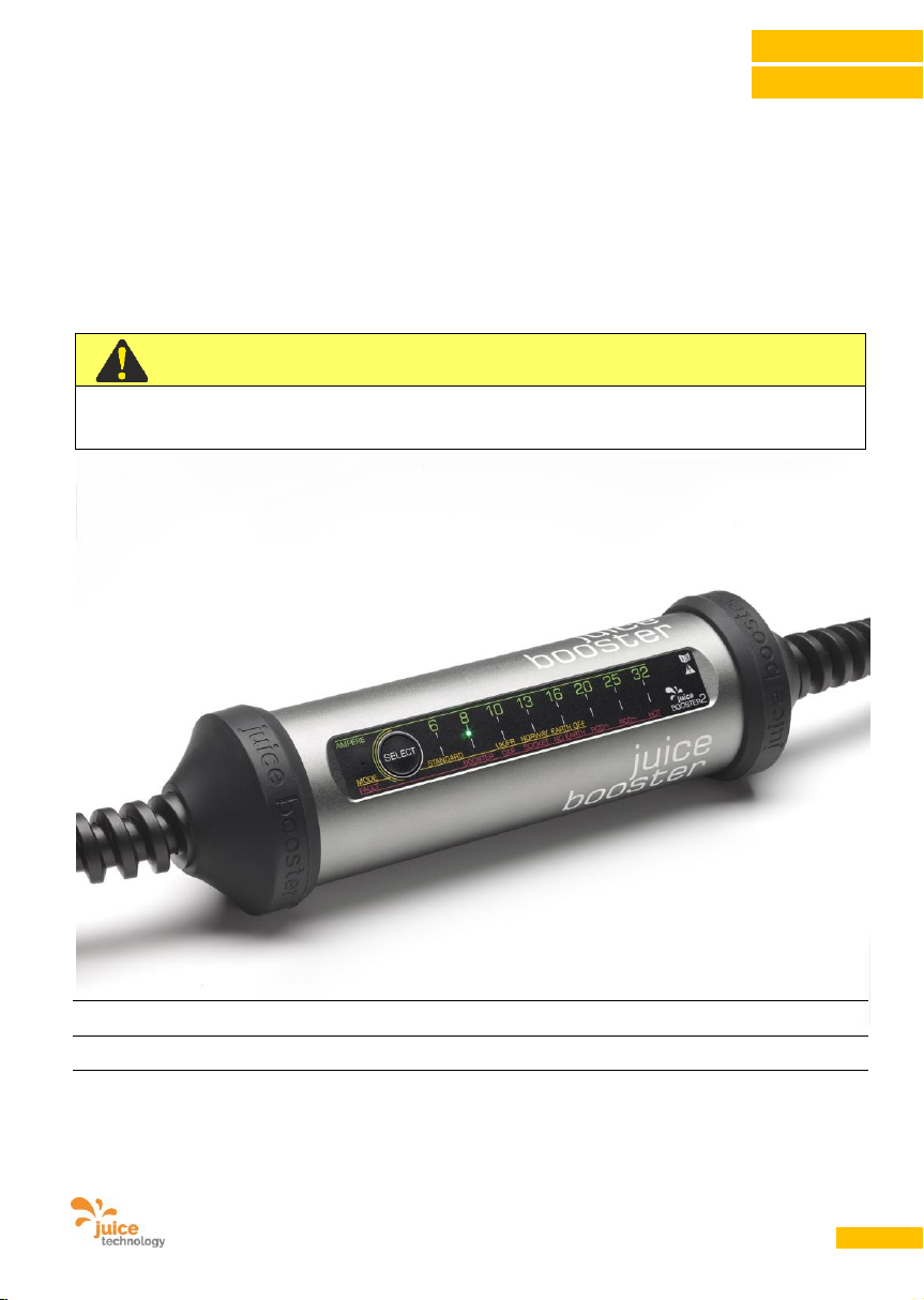
Benutzerhandbuch JUICE BOOSTER 2 [EL-JB2, EA-JB2] Version 2.00 DE
1
DEUTSCH
Bedienungsanleitung | User Manual
JUICE BOOSTER 2
WICHTIG | IMPORTANT
Handbuch vor Inbetriebnahme des Geräts lesen!
Read this manual before you start using the device!
Mobile Ladestation für Elektrofahrzeuge / Sicherheitsladekabel
IC-CPD (In-Cable Control and Protection Device for EV charging)
Handbuch gemäss DIN EN 82079-1:2013-06; Rel. 2.00 DE
gültig für Artikel-Nummern: EL-JB2*, EA-JB2* | P/N JTJB2-EU1R1…, JTJB2-EU1R2…, JTJB2-EU1R3…
Die Missachtung dieser Anweisung kann zu Verletzung, Tod, Schäden am Gerät
und der Umgebung führen.
Anleitung sicher aufbewahren für späteres Nachschlagen.
ENGLISH
Page 2
Benutzerhandbuch JUICE BOOSTER 2 [EL-JB2, EA-JB2] Version 2.00 DE
2
DEUTSCH
1. Allgemeines
Diese Bedienungsanleitung gehört zu Ihrem
JUICE BOOSTER 2. Sie enthält wichtige
Informationen zur Inbetriebnahme und
Handhabung.
Lesen Sie die Bedienungsanleitung,
insbesondere die Sicherheitshinweise, sorgfältig
durch, bevor Sie den JUICE BOOSTER 2
einsetzen.
Die Bedienungsanleitung basiert auf den in der
Europäischen Union gültigen Normen und
Regeln. Beachten Sie zusätzlich die jeweiligen
landesspezifischen Richtlinien und Gesetze.
Bewahren Sie die Bedienungsanleitung für die
weitere Nutzung auf. Wenn Sie den JUICE
BOOSTER 2 an Dritte weitergeben, geben Sie
unbedingt diese Bedienungsanleitung mit.
2. Zeichenerklärung
Die folgenden Symbole und Signalworte werden in dieser Bedienungsanleitung, auf dem JUICE BOOSTER
2 oder auf der Verpackung verwendet.
GEFAHR
Lebensgefahr!
Bezeichnet eine Gefährdung mit einem hohen
Risikograd, die, wenn sie nicht vermieden wird,
den Tod, schwere Verletzungen oder schwere
Sachbeschädigung zur Folge haben kann.
WARNUNG
Stromschlaggefahr!
Bezeichnet eine Gefährdung mit einem mittleren
Risikograd, die, wenn sie nicht vermieden wird,
den Tod, Verletzungen oder bedeutende
Sachbeschädigung zur Folge haben kann.
VORSICHT
Beschädigungsgefahr!
Bezeichnet eine Gefährdung mit einem niedrigen
Risikograd, die, wenn sie nicht vermieden wird,
eine geringfügige oder mässige Verletzung oder
Sachbeschädigung zur Folge haben kann.
Die folgenden Symbole sind auf dem JUICE BOOSTER aufgebracht und bedeuten folgendes:
Konformitätserklärung (Communauté Européenne). Mit diesem Symbol gekennzeichnete
Produkte erfüllen alle anzuwendenden Gemeinschaftsvorschriften des europäischen
Wirtschaftsraums.
Mit diesem Symbol gekennzeichnete Produkte erfüllen die EU-Richtlinien zur Beschränkung
der Verwendung bestimmter gefährlicher Stoffe in Elektro- und Elektronikgeräten.
Page 3
Benutzerhandbuch JUICE BOOSTER 2 [EL-JB2, EA-JB2] Version 2.00 DE
3
DEUTSCH
Dieses Symbol bezeichnet die unterste maximale Betriebstemperatur in °C, bei der das
Gerät betrieben werden kann.
Dieses Symbol bezeichnet die Schutzart gegenüber Umgebungsbedingungen und
zusätzlich den Schutz von Menschen gegen potentielle Gefährdung bei deren Benutzung.
IP67 bedeutet geschützt gegen Staub in schädigender Menge und zeitweiliges
Untertauchen.
Schutzklasse I. Mit diesem Symbol gekennzeichnete Produkte erfüllen die Norm DIN EN
61140. Alle Metallteile, die während des Betriebs und der Wartung im Fehlerfall Spannung
aufnehmen können, sind mit dem Erdleiter verbunden.
Dieses Symbol bezeichnet, dass der Erdleiter fix durchgeschaltet ist.
Bezeichnet die Art der Entsorgung. Altgeräte dürfen nicht mit dem Hausmüll entsorgt
werden. Jeder Verbraucher ist verpflichtet, Altgeräte getrennt vom Hausmüll zu entsorgen
z.B. durch Abgabe an einer Sammelstelle einer Gemeinde. Durch die fachgerechte
Verwertung werden negative Auswirkungen auf die Umwelt vermieden.
Dieses Zeichen ist das internationale Symbol für Recycling und steht für wiederverwertbare
Güter. Entsorgen Sie die Verpackung sortenrein. Geben Sie Pappe und Karton zum
Altpapier/Altkarton, Folien in die Werkstoff-Sammlung.
3. Inhaltsverzeichnis
1. .............. Allgemeines .................................................................................................................................................................................................. 2
2. .............. Zeichenerklärung .......................................................................................................................................................................................... 2
3. .............. Inhaltsverzeichnis ......................................................................................................................................................................................... 3
4. .............. Identifizierung ................................................................................................................................................................................................ 4
5. .............. Bestimmungsgemässer Gebrauch .............................................................................................................................................................. 4
6. .............. Sicherheitshinweise / Wichtige Schutzmassnahmen .................................................................................................................................. 5
7. .............. Produktbeschreibung ................................................................................................................................................................................... 7
8. .............. Technische Daten ....................................................................................................................................................................................... 11
9. .............. Stromversorgung ........................................................................................................................................................................................ 12
10. ............ Funktionen .................................................................................................................................................................................................. 13
11. ............ Vorbereitung des Produkts für den Gebrauch .......................................................................................................................................... 15
12. ............ Anforderungen an die Anschluss-Steckdosen .......................................................................................................................................... 16
13. ............ Betriebsanleitung ........................................................................................................................................................................................ 17
14. ............ Instandhalten und Reinigen ....................................................................................................................................................................... 21
15. ............ Störungen und Fehler ................................................................................................................................................................................. 21
16. ............ Massnahmen bei Unfällen mit elektrischem Strom................................................................................................................................... 26
17. ............ Massnahmen bei Elektrobrand .................................................................................................................................................................. 27
18. ............ Garantie....................................................................................................................................................................................................... 28
19. ............ Servicehinweis / Kundendienst .................................................................................................................................................................. 30
20. ............ Hinweise ...................................................................................................................................................................................................... 30
21. ............ Anbieter ....................................................................................................................................................................................................... 30
22. ............ Entsorgung / Recycling .............................................................................................................................................................................. 31
Page 4
Benutzerhandbuch JUICE BOOSTER 2 [EL-JB2, EA-JB2] Version 2.00 DE
4
DEUTSCH
4. Identifizierung
4.1. Produktmarke und Typbezeichnung
Produktmarke: JUICE BOOSTER 2
Artikelbezeichnung: Mobile Ladestationen für Elektro-Fahrzeuge
Artikelnummer: EL-JB2*, EA-JB2*
Produktnummer (P/N): JTJB2-EU1R1…, JTJB2-EU1R2…, JTJB2-EU1R3…
Typ: IC-CPD (In-Cable Control and Protection Device for EV charging)
4.2. Konformitätserklärung mit den Produktnormen
Die JUICE BOOSTER 2 trägt das -Zeichen.
Die EU-Konformitätserklärung kann bei nachfolgender Adresse angefordert werden:
JUICE TECHNOLOGY AG, Gewerbestrasse 7, CH-6330 Cham, Schweiz
(Achtung: Keine Material- oder Gerätesendungen an diese Adresse)
5. Bestimmungsgemässer Gebrauch
Benutzen Sie das Gerät ausschliesslich zum Laden
der Batterie von Elektrofahrzeugen, die mit einem
Typ 2-Stecker ausgerüstet sind.
GEFAHR
Lebensgefahr!
Verwenden Sie den JUICE BOOSTER 2 nur wie in
der Betriebsanleitung beschrieben. Jede andere
Verwendung gilt als nicht bestimmungsgemäss
und kann zu Sachschäden oder zu schweren
Personenschäden führen. Der JUICE BOOSTER 2
ist kein Kinderspielzeug.
Verwenden Sie ausschliesslich
JUICE CONNECTOR-Sicherheitsadapter und
JUICE CONNECTOR-Sicherheitsverlängerungskabel von Juice Technology AG, die mit einer
automatischen Stromstärken-Erkennung ausgerüstet sind. Die Verwendung anderer Adapter
und/oder Kabel ist verboten und gilt als nicht
bestimmungsgemäss. Missbrauch dieser Art kann
zu schweren Sachschäden und/oder zu schweren
Personenschäden führen.
Der Hersteller oder Händler lehnt jede Haftung ab
für Schäden, die durch nicht
bestimmungsgemässen Gebrauch entstanden
sind und die Gerätegarantie erlischt.
Page 5
Benutzerhandbuch JUICE BOOSTER 2 [EL-JB2, EA-JB2] Version 2.00 DE
5
DEUTSCH
6. Sicherheitshinweise / Wichtige Schutzmassnahmen
GEFAHR
Stromschlaggefahr!
• Öffnen Sie niemals das Gehäuse! Beim
Berühren von unter Strom stehenden Teilen
besteht akute Lebensgefahr.
• Trennen Sie die Anschluss-Stecker nie
unter Last. Es können elektrische Funken
entstehen und die Juice Sicherheitsstecker
und -kupplungen werden dadurch
übermässig abgenutzt und verkürzen deren
Lebensdauer. Stoppen Sie zuerst den
Ladevorgang beim Auto, bevor Sie die
Strecker trennen.
• Achten Sie darauf, dass Sie Kabel nie
aufgerollt oder in Schlaufenform
zusammengelegt in Betrieb nehmen.
Dadurch kann es zu einem Hitzestau
kommen. Dies kann bis zum Abschmelzen
der Isolation und zu Brand führen. Berühren
Sie in einem solchen Fall die Teile niemals
ungeschützt von Hand, da Sie direkt mit
stromführenden Elementen in Kontakt
kommen könnten. Beim Berühren von unter
Strom stehenden Teilen besteht akute
Lebensgefahr.
• Stellen Sie sicher, dass sich der JUICE
BOOSTER 2 nie in der Umgebung von
explosionsfähigen Dämpfen oder Gasen
befindet. Beim Gebrauch des JUICE
BOOSTER 2 können bei den
Schaltvorgängen im Gehäuse winzige
elektrische Funken entstehen, die zu
Explosionen führen könnten.
• Entdecken Sie Schäden am JUICE
BOOSTER 2 und/oder seiner Komponenten
im laufenden Betrieb, ist das Gerät sofort
durch Ausschalten der Haussicherung vom
Stromnetz zu trennen und mit der
Servicestelle Kontakt aufzunehmen. Berühren
Sie in diesem Fall keinerlei Metallteile
und/oder Kabel und/oder nasse Teile.
• Beim nicht sachgemässen Gebrauch des
JUICE BOOSTER 2 besteht Lebensgefahr!
• Führen Sie für Notfälle stets ein Mobiltelefon
mit sich.
• Informieren Sie sich über Massnahmen bei
Unfällen mit elektrischem Strom und bei
einem Elektrobrand. Diese sind unter Punkt
16 und 17 in der Bedienungsanleitung
beschrieben.
WARNUNG
Lebensgefahr!
• Lassen Sie niemals Verpackungsmaterial
herumliegen. Plastikfolien, -taschen oder
andere Verpackungsteile können zu einem
gefährlichen Spielzeug für Kinder werden. Es
droht Erstickungsgefahr!
• Kontrollieren Sie das Gerät vor jeder
Inbetriebnahme und Nutzung auf Mängel.
Nehmen Sie es nicht in Betrieb, wenn Sie
Unregelmässigkeiten oder Beschädigungen
am Gehäuse, Kabel, Stecker oder
Steckdosen feststellen.
• Der Betreiber muss grundsätzlich die in
seinem Land geltenden nationalen
Vorschriften bezüglich Betrieb,
Funktionsprüfung, Reparatur und Wartung
von elektronischen Geräten beachten.
• Schliessen Sie den JUICE BOOSTER 2
ausschliesslich an korrekt installierte
Steckdosen mit intakter Erdung an.
• Fehlt der Erdleiter in der Zuleitung und
betreiben Sie den JUICE BOOSTER 2 im
MODE „NORWAY“ oder „EARTH OFF“, kann
technologietypisch ein sehr feines Kribbeln
am Gehäuse spürbar sein. Dieses rührt von
einem Ableitstrom im mA-Bereich her und ist
sowohl normal wie ungefährlich.
Page 6
Benutzerhandbuch JUICE BOOSTER 2 [EL-JB2, EA-JB2] Version 2.00 DE
6
DEUTSCH
• Die Anschlussdaten des JUICE BOOSTER 2
müssen mit denen des Versorgungsnetzes
unbedingt übereinstimmen.
• Schützen Sie Ihr Gerät vor stehender Nässe,
starkem Staub, aggressiven Flüssigkeiten
und Dämpfen. Achten Sie darauf, dass das
Gerät nicht in einer Wasserlache liegt und
dass sich (z.B. bei Regen oder tauendem
Schnee) keine solche um das oder auf dem
Gerät bilden kann.
• Betreiben Sie den JUICE BOOSTER 2 nicht
in unmittelbarer Nähe von Wärmequellen.
• Überprüfen Sie während des Ladevorgangs
regelmässig die Temperatur der Steckdosen
und Leitungen. Brechen Sie bei Hitze die
Ladung sofort ab. Hitze ist dann gegeben,
wenn Sie das Kabel oder den Stecker mit der
blossen Hand nicht mindestens 20
Sekunden umschlossen halten können.
• Wird der JUICE BOOSTER 2 längerer
Sonnenbestrahlung ausgesetzt oder in
heissem Klima betrieben, kann sich das
Gehäuse heiss anfühlen. Das ist ein Zeichen
hervorragender Wärmeableitung und stellt
kein Problem dar. Halten Sie in solchen
Fällen das Gerät am Kabel oder an den
Gummikappen.
• Montage-, Installations- und
Reparaturarbeiten an der Strominstallation
dürfen nur durch qualifizierte Fachkräfte
erfolgen, die aufgrund ihrer Ausbildung,
Kenntnisse und Erfahrungen sowie Kenntnis
der einschlägigen Normen und
Bestimmungen in der Lage sind, Arbeiten an
elektrischen Anlagen auszuführen und
mögliche Gefahren selbständig zu erkennen
und zu vermeiden.
• Durch unsachgemässe Verwendung,
Reparaturen oder Strominstallationsarbeiten
an einer Zuleitung zu einer Steckdose für den
JUICE BOOSTER 2 können erhebliche
Gefahren und Risiken für den Benutzer
entstehen, für die der Hersteller nicht haftet.
• Personen, die aufgrund ihrer physischen,
sensorischen oder geistigen Fähigkeiten
oder ihrer Unerfahrenheit oder Unkenntnis
nicht in der Lage sind, den JUICE BOOSTER
2 sicher zu bedienen, dürfen dieses Gerät
nicht ohne Aufsicht oder Anweisung durch
eine verantwortliche Person benutzen.
• Stellen Sie sicher, dass Kinder, Unmündige
sowie generell Unbefugte und Tiere keinen
Zugriff zum JUICE BOOSTER 2 haben.
Lassen Sie Kinder nie mit dem Gerät spielen.
VORSICHT
Beschädigungsgefahr!
• Betreiben Sie das Produkt maximal im
Temperaturbereich von -25 °C bis +45 °C.
Setzen Sie den JUICE BOOSTER 2 und
dessen Kabel nicht länger starker
Sonneneinstrahlung aus.
• Benutzen Sie keine scharfen oder spitzen
Gegenstände, um die Verpackung zu öffnen.
Der JUICE BOOSTER 2 oder die Kabel
können dadurch beschädigt werden.
• Kontrollieren Sie, ob die Verpackung, das
Gerät und mitgelieferte Einzelteile wie
Adapter etc. Schäden aufweisen. Ist dies der
Fall, nehmen Sie den JUICE BOOSTER 2
nicht in Betrieb. Wenden Sie sich über die auf
der Garantiekarte – sowie unter Punkt 19
dieser Bedienungsanleitung – angegebene
Serviceadresse an den Hersteller.
• Stecker und JUICE CONNECTOR-Verbinder
stets absolut trocken halten. Ungesteckt ist
kein Stecker wasserdicht, deshalb bei
Nichtgebrauch stets Schutzkappen
aufsetzen.
ACHTUNG: E-Fahrzeug-Ladeverbinder sind
High-Tech-Hochleistungs-Teile. Sichern Sie
Ihre Investition, indem Sie die Verbinder
immer sauber und trocken halten.
Page 7
Benutzerhandbuch JUICE BOOSTER 2 [EL-JB2, EA-JB2] Version 2.00 DE
7
DEUTSCH
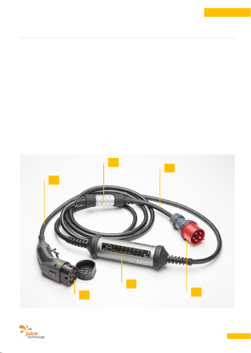
7. Produktbeschreibung
7.1. Lieferumfang
Standard Ausstattung:
IC-CPD mit folgenden Steckern/Kupplungen:
• Fahrzeugseitig Typ 2-Kupplung (oder Typ 1-Kupplung)
• Netzseitig JUICE CONNECTOR-Sicherheitsstecker
• Ein oder mehrere JUICE CONNECTOR-Sicherheitsadapter
Bestandteile:
A. JUICE BOOSTER 2
B. JUICE CONNECTOR-Sicherheitsverbindung
C. Typ 2-Kupplung (zum Anschluss ans Fahrzeug)
D. Netzadapter (verschiedene Adapter erhältlich)
E. Netzstecker (in diesem Fall CEE32: 400 V, 32 A, 3phasig)
F. Hochleistungskabel 400 V, 32 A, 3phasig mit Steuersignalen
E
B
D
F
C
A
Page 8
Benutzerhandbuch JUICE BOOSTER 2 [EL-JB2, EA-JB2] Version 2.00 DE
8
DEUTSCH
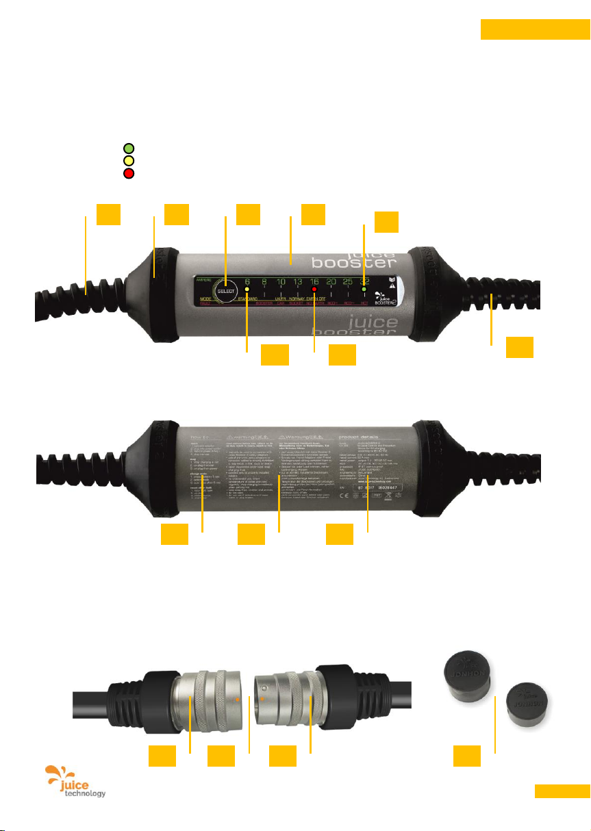
Gerät-Vorderseite:
G. Anschluss netzseitig mit JUICE CONNECTOR-Sicherheitsadapter
H. Gehäuse
I. Rutschhemmende Gummischutzteile
J. Taster für Ladestärke/Modus
K. LED grün: AMPERE (automatisch eingestellter oder individuell reduzierter Ampère-Wert)
L. LED gelb: MODE (zeigt den vorgewählten Modus an)
M. LED rot: FAULT (zeigt im Fehlerfall die Ursache an)
N. Anschluss-Kabel fahrzeugseitig mit Typ 2-Kupplung (oder alternativ Typ 1-Kupplung)
Gerät-Rückseite:
O. Kurzanleitung
P. Warnhinweise
Q. Produktangaben und Seriennummer
JUICE CONNECTOR:
R. JUICE CONNECTOR-Sicherheitsstecker (m), führt zum JUICE BOOSTER 2
S. JUICE CONNECTOR-Sicherheitskupplung (f), ist Teil des Adapters mit Netzstecker
T. Mechanische Führungen lassen das Zusammenstecken nur in der korrekten Position zu
(Orientierungshilfe mit orangen Punkten). Zusammenstecken bis zum Klick-Geräusch. Entfernen
durch zurückziehen des Überwurfrings (S).
U. Schutzkappen, mitgeliefert für alle JUICE CONNECTOR.
G
H
O
P
Q
K
L
J
M
I
N
S
T
R
U
Page 9
Benutzerhandbuch JUICE BOOSTER 2 [EL-JB2, EA-JB2] Version 2.00 DE
9
DEUTSCH
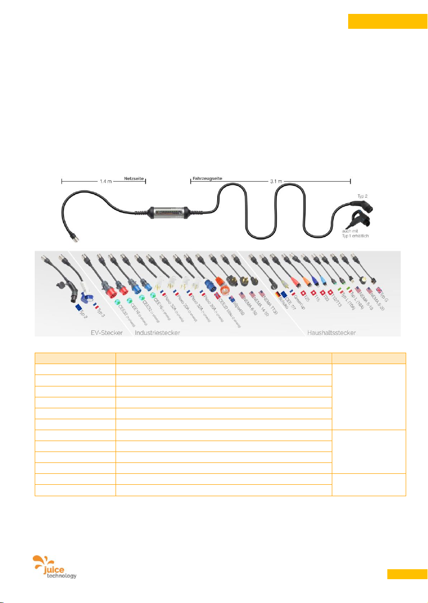
7.2. Optionale Adapter
JUICE CONNECTOR-Sicherheitsadapter erkennen die Stromstärken der jeweiligen Steckdosen, an denen
geladen wird. Das Ladegerät stellt die entsprechende Ladestärke automatisch ein.
Je nach Land empfehlen wir unterschiedliche JUICE CONNECTOR-Sicherheitsadapter oder
-adaptersets. Diese sind separat erhältlich bei den Verkaufsstellen des JUICE BOOSTER 2. Eine Auswahl
davon finden Sie auf der Produkteseite unter www.juice-technology.com/juice-booster aufgeführt.
Für den sicheren und universellen Anschluss an alle üblichen Steckdosen empfehlen wir den Einsatz eines
solchen Adaptersets. Einige Beispiele erhältlicher Adapter:
Adapter, z.B.
Verwendung / Bezeichnung
Klasse
CEE 7/7 Schuko
EU
Haushalt
T13, T23
Schweiz
Typ L
Italien
Typ G
Commonwealth Countries (BS 1363)
Typ AUS
Australia
T15, T25
Schweiz 400 V, 3-Phasen-Stecker
CEE16 / 230 V
blauer Stecker 1phasig („Campingstecker“)
Industrie
CEE32 / 230 V
blauer Stecker 1phasig (UK, FR)
CEE16 / 400 V
roter Stecker 3phasig
CEE32 / 400 V
roter Stecker 3phasig
Typ 2 / 32 A
Stecker für Typ 2-Dosen
E-Mobility
Typ 3c
Stecker für Typ 3-Dosen (speziell FR)
Das Adaptersortiment wird laufend erweitert. Die vollständige und aktuelle Liste der über 25 erhältlichen
Adapter finden Sie unter www.juice-technology.com/juice-booster
Page 10
Benutzerhandbuch JUICE BOOSTER 2 [EL-JB2, EA-JB2] Version 2.00 DE
10
DEUTSCH
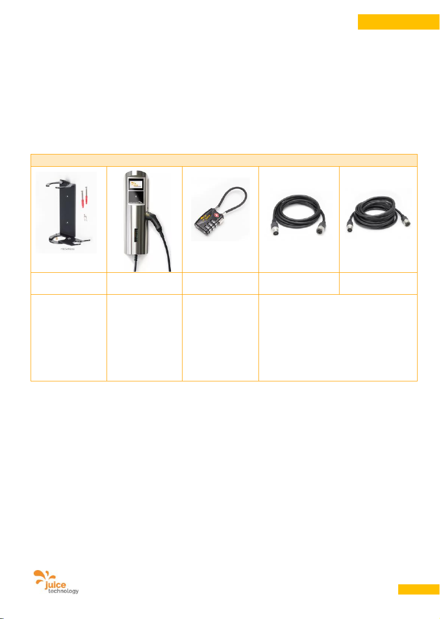
7.3. Weitere Optionen
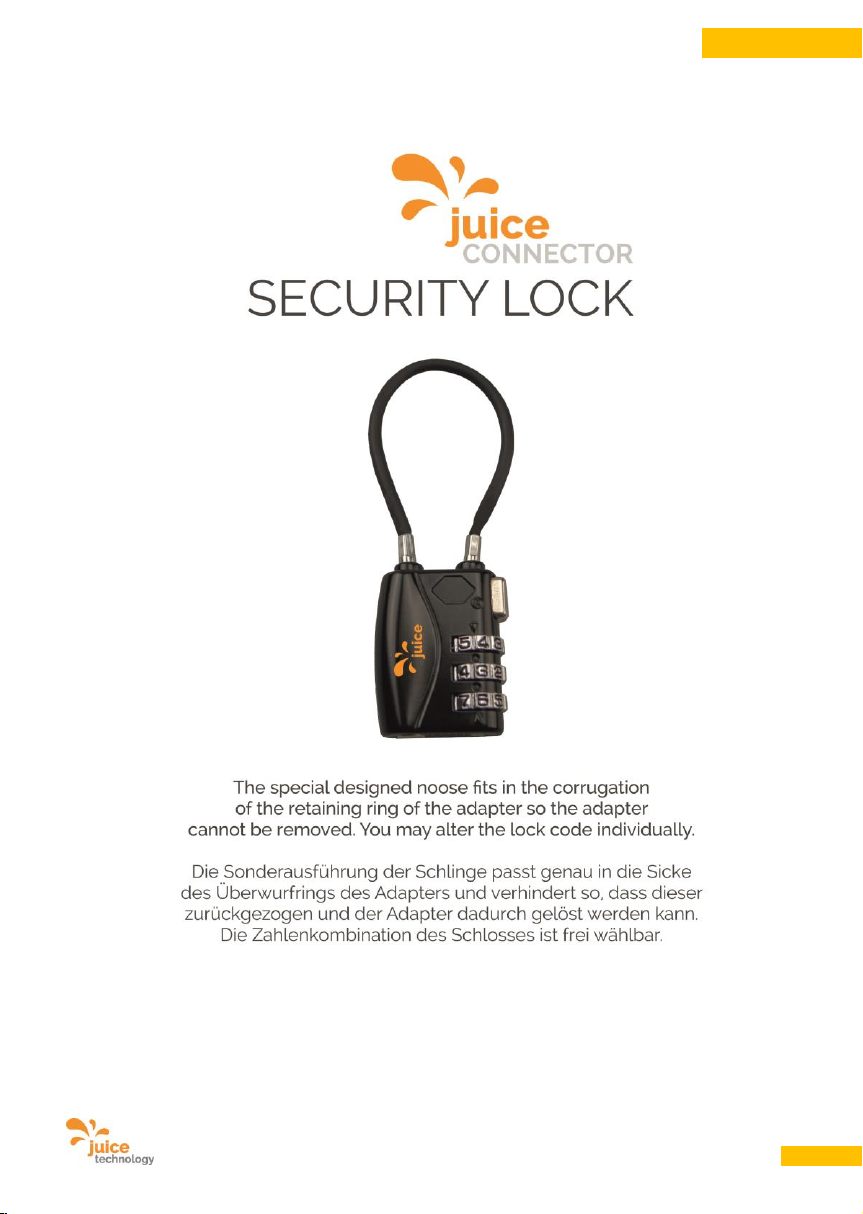
Separat erhältlich ist ein Sicherheitsschloss für die JUICE CONNECTOR-Sicherheitsadapter, das das
unbefugte ausstecken und ggf. entwenden verhindert.
Weitere Optionen wie Wandhalterung für den privaten und halböffentlichen Bereich, Ansteuerung für
Lastmanagement etc. sind separat erhältlich. Der JUICE BOOSTER 2 kann damit auch als optimale, sehr
sichere und kostengünstige Wallbox genützt werden. Gut zu wissen: Er enthält bereits die sonst
kostspielige DC-Fehlerstromerkennung (FI B).
Zubehör (Beispiele)
Wandhalterung
Juice Charger 2
Sicherheitsschloss
Verlängerung
5m
Verlängerung
10m
Offene
Wandhalterung,
optional
abschliessbar.
LastmanagementModule und
geeichter Zähler
enthalten.
Optionale
Zahlungs- und
Freischaltungssysteme.
Verhindert
wirkungsvoll das
Ausstecken von
Adaptern und
Verlängerungen.
Hinweis: in der Norm nicht vorgesehen,
deshalb nicht CE-konform. Da die
Verbindungen aber wasserfest sind (IP67)
und die automatische Adaptererkennung
übertragen wird, ist das Produkt
ungefährlich und sicher einsetzbar.
Die aktuelle Liste von Zubehör und Erweiterungen finden Sie unter
www.juice-technology.com/juice-booster
Page 11

Benutzerhandbuch JUICE BOOSTER 2 [EL-JB2, EA-JB2] Version 2.00 DE
11
DEUTSCH
8. Technische Daten
8.1. Konstruktion
• Gehäuseabmessungen Länge 265 mm, Durchmesser 70 mm
• Gewicht 1.0 kg ohne Kabel, 3.2 kg mit Kabel und Stecker
• Material Aluminium eloxiert mit Gummikappen
• Materialstärke 3 mm
• Farbe anthrazit metallic, Gummikappen und Kabel schwarz
• Schutzart IP67 (geschützt gegen Staub in schädigender Menge
und kurzzeitiges Untertauchen)
• Stoss- und Fallsicherheit Überfahrsicher mit 2000 kg Radlast (Gummischutz kann bersten,
Gehäuse und Stecker können zerkratzt oder verbogen werden, aber es
werden keine stromführenden Teile freigelegt.)
Fallsicher für Höhen bis 100 cm
• Temperaturbereich Lagerung: -30 °C bis +60 °C
Betrieb: -25 °C bis +45 °C
• Stecker netzseitig JUICE CONNECTOR-Sicherheitsstecker, 400 V, 32 A, 3ph.,
hochleitfähige Silberkontakte, Kabellänge 1.4 m
• Adapter netzseitig JUICE CONNECTOR-Sicherheitsadapter in zahlreichen
Ausführungen, mittels JUICE CONNECTOR-Sicherheits kupplung anschliessbar an den JUICE BOOSTER 2.
Die Sicherheitsadapter übermitteln automatisch den
maximal beziehbaren Ampère-Wert ans Gerät
• Kupplung fahrzeugseitig Typ 2 (EN62196), 400 V, 32 A, 3phasig, oder
Typ 1 (EN62196), 400 V, 32 A, 1phasig,
hochleitfähige Silberkontakte, Kabellänge 3.1 m
8.2. Elektrotechnische Daten
• FI-Fehlerstromschutz RCD DC 6 mA, AC/DC 30 mA mit Schutzleiterüberwachung
• Eingangsstrom 230 V, 6 – 32 A (1phasig) oder 400 V, 6 – 32 A (3phasig) AC
• Ausgangsleistung abhängig vom Eingangsstrom 1.4 – 22.0 kW AC
8.3. CE-Konformität
• Normen IEC 62752, 62196,
61851-Mode2, 61851-Mode3 (mit Adapter Typ 2, Typ 3c),
EMV, RoHS
Page 12
Benutzerhandbuch JUICE BOOSTER 2 [EL-JB2, EA-JB2] Version 2.00 DE
12
DEUTSCH
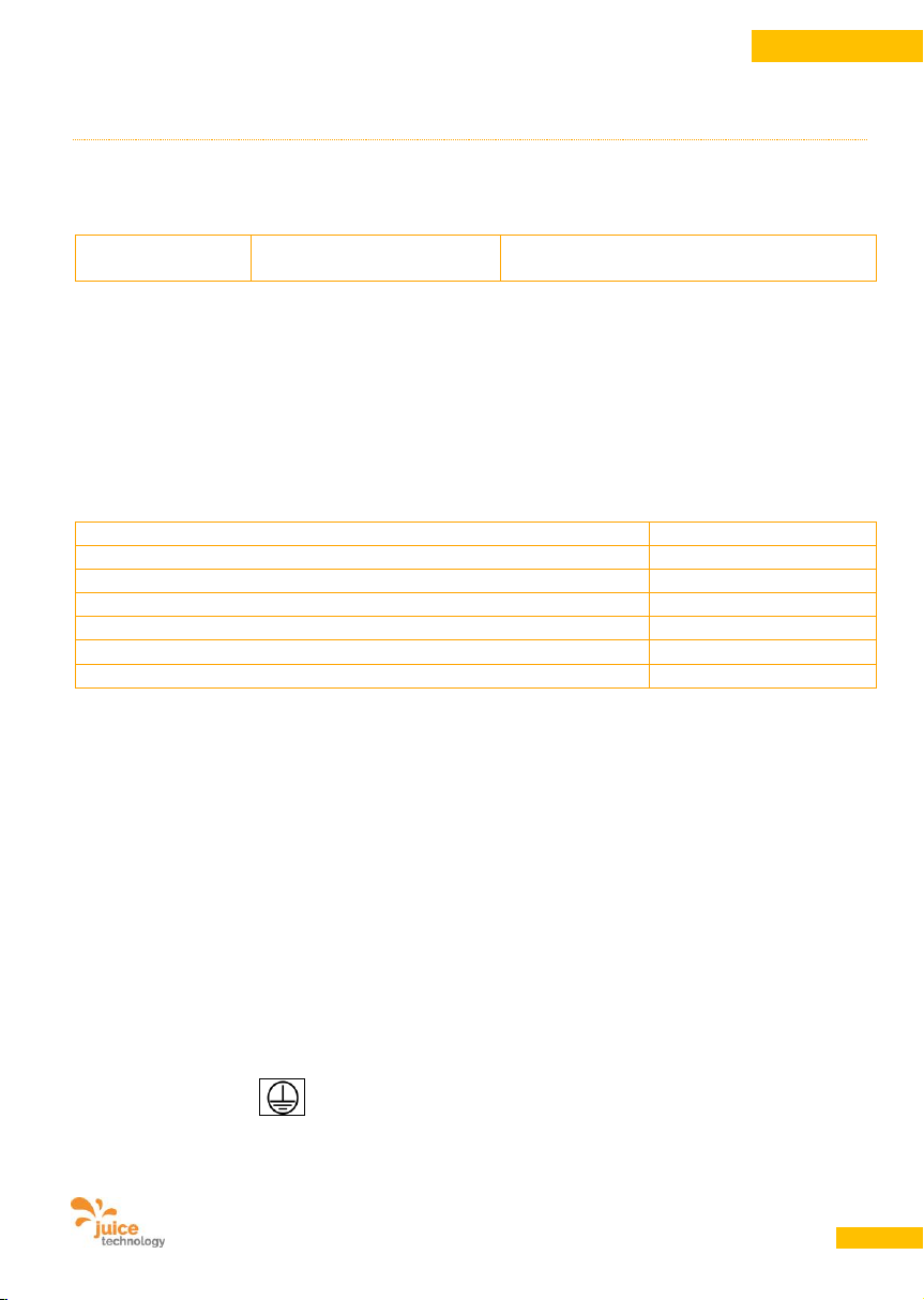
9. Stromversorgung
9.1. Stromanschluss / Eingangsspannung
Beachten Sie folgende Maximalanschlusswerte:
Art.-Nr.:
EL-JB2 / EA-JB2
JUICE BOOSTER 2
32 A Drehstrom (3phasig), 400 V * / **
* 1phasiger Anschluss mit gleichen Ampère-Werten ist möglich, jedoch wird damit nur 1/3 der
Ladestärke in kW erreicht.
** Anschluss mit geringeren Ampère-Werten ist möglich. Dazu muss der JUICE BOOSTER 2 zuerst
netzseitig angeschlossen und danach die Stromstärke eingestellt werden. Danach kann das
Ladegerät mit dem Elektroauto verbunden und der Ladevorgang gestartet werden.
9.2. Energieverbrauch
Stromversorgung bei 32 A und 400 V (Drehstrom = 3phasig):
max. 22 kW
Stromversorgung bei 16 A und 400 V (Drehstrom = 3phasig):
max. 11 kW
Stromversorgung bei 16 A und 230 V (3phasig, laden 2phasig):
max. 7.4 kW
Stromversorgung bei 32 A und 230 V (1phasig):
max. 7.4 kW
Stromversorgung bei 16 A und 230 V (1phasig):
max. 3.7 kW
Stromversorgung bei 8 A und 230 V (1phasig):
max. 1.8 kW
Standby (ohne laufenden Ladevorgang)
< 1 W
Hinweis zur Kostenberechnung: Wird die Leistung von 22 kW während einer Stunde bezogen, beträgt
der Energieverbrauch 22 kWh. Kostet die kWh ("Kilowattstunde") z.B. EUR -,30 entsprechen 22 kWh also
Kosten von rund EUR 6,60.
Die Formel für allfällige Kostenabrechnungen lautet:
Ampère * 230 V * Phasen = Leistung in Watt (W)
Leistung in W / 1000 = Leistung in Kilowatt (kW)
Leistung in kW * Zeit in Stunden * Preis pro kWh = Stromkosten
Standby-Stromverbrauch: Sie können, z.B. zu Hause, den JUICE BOOSTER 2 das ganze Jahr
angeschlossen lassen, es schadet dem Gerät nicht. Der Standby-Stromverbrauch ist äusserst gering, die
Kosten liegen bei ca. CHF / EUR / USD 1,- pro Jahr.
9.3. Schutzklassen
• Schutzklasse I
Page 13
Benutzerhandbuch JUICE BOOSTER 2 [EL-JB2, EA-JB2] Version 2.00 DE
13
DEUTSCH
10. Funktionen
10.1. Grundfunktion
Der JUICE BOOSTER 2 dient zum Aufladen von
Elektrofahrzeugen. Mit den entsprechenden
Adaptern ist er sowohl eine vollwertige tragbare
Ladestation wie auch ein Ladekabel zum
Anschluss an öffentliche Ladestationen oder
Wallboxen.
Der JUICE BOOSTER 2 erkennt den
angeschlossenen Netzstecker und damit die
maximale zulässige Ladestärke. Sobald das
Kabel mit einer passenden, funktionsfähigen
Steckdose und anschliessend mit dem
Fahrzeug verbunden wird und das Fahrzeug
ladebereit ist, startet der Ladevorgang
automatisch.
Aus Sicherheitsgründen verhindert der JUICE
BOOSTER 2, dass eine höhere Ladestärke
eingestellt werden kann. Eine Reduktion der
Ladestärke ist mittels Drucktaster jedoch
möglich. Der JUICE BOOSTER 2 ignoriert
Manipulationen am Drucktaster während des
Ladevorganges. Somit können Unbefugte
weder einen Ladevorgang unterbrechen noch
die Stromstärke verändern.
Da das Fahrzeug im abgeschlossenen Zustand
den Stecker auch bei Ladeunterbruch nicht
freigibt, können Unbefugte weder am Fahrzeug
ausstecken noch den JUICE BOOSTER 2
entwenden.
Um die mittels JUICE CONNECTORSicherheitsstecker angeschlossenen Adapter
vor Entwendung zu schützen, lassen sie sich
mit separat erhältlichen Sicherheitsschlössern
blockieren. Dadurch wird das Ausstecken und
Entfernen verunmöglicht.
10.2. Verwendung an Typ 2- und an
Typ 3-Ladesäulen mit
Verriegelungsmechanismus
Bevor der Ladevorgang startet, wird am
Fahrzeug und an der Ladesäule der Stecker
verriegelt.
Eine Entriegelung kann nur vorgenommen
werden, wenn der Ladevorgang – durch
entsprechenden Befehl im Elektroauto oder ggf.
über eine App-Steuerung des Fahrzeugs –
abgebrochen wird. Danach können der Stecker
an der Dose sowie auch die Typ 2-Kupplung
am Fahrzeug abgezogen werden.
10.3. Verwendung an Haushalts- und
Industriesteckdosen (ohne
Verriegelung)
Der Ladevorgang startet wie unter 13.2
beschrieben automatisch. Die Kupplung am
Auto wird verriegelt. Eine Entriegelung der
Kupplung erfolgt durch den entsprechenden
Befehl im Auto, indem der Ladevorgang
abgebrochen wird.
Sofern Unbefugte während des Ladevorgangs
das Kabel von der Steckdose trennen, so wird
bei erneutem Einstecken der Ladevorgang
automatisch mit der zuletzt erkannten bzw.
manuell reduziert eingestellten Stromstärke
fortgesetzt.
VORSICHT
Beschädigungsgefahr!
Haushalts- und Industriesteckdosen verfügen
über keinen Verriegelungsmechanismus.
Vermeiden Sie während des laufenden Ladevorgangs das Ziehen des netzseitigen Steckers
sowie auch des JUICE CONNECTORs! Es führt
zur Verschmauchung der Steckkontakte. Zudem
kann die Ladeelektronik und -elektrik in Ihrem
Auto sowie in Ihrem JUICE BOOSTER 2
beschädigt werden.
Page 14
Benutzerhandbuch JUICE BOOSTER 2 [EL-JB2, EA-JB2] Version 2.00 DE
14
DEUTSCH
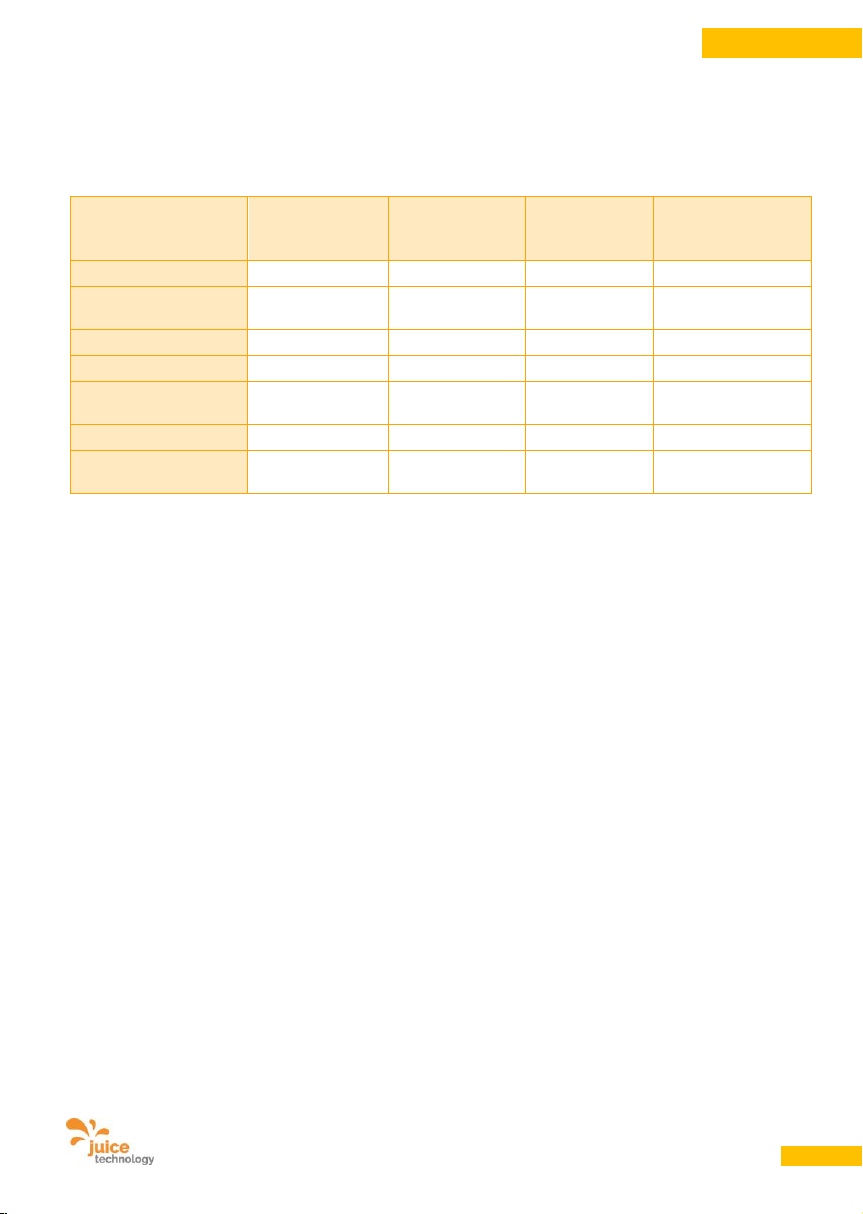
10.4. Lademöglichkeit
Folgende Beispiele zeigen den Zusammenhang des Ladestroms und der Ladezeit auf:
Netz-Steckdose
Typ 2Ladestation
Industriedose
CEE 32 rot
Industriedose
CEE 16 rot
Haushaltdose
Schuko
Deutschland
Eingangsleistung
32 A
32 A
16 A
13 A
Spannung
400 V (3phasig)
400 V (3phasig)
400 V
(3phasig)
230 V (1phasig)
Ausgangsleistung
max. 22 kW
max. 22 kW
max. 11 kW
max. 3.0 kW
Lademodus
3 2 2
2
Fahrzeugkommunikation
Ja
Ja
Ja
Ja
Ladezeit*
ca. 1 h
ca. 1 h
ca. 2 h
ca. 6 h
Ladung pro Std.**
ca. 100 - 150 km
ca. 100 - 150
km
ca. 50 - 75 km
ca. 13 - 20 km
* ausgehend von einem im Fahrzeug eingebauten Gleichrichter mit einer Leistung
entsprechend der Eingangsleistung sowie einer Batterie mit 22 kWh. Bei anderen
Batteriegrössen verändert sich die Ladezeit linear.
** abhängig vom zu ladenden Fahrzeug und vom Fahrstil
10.5. Einsatzgebiete
An beliebigen korrekt installierten Steckdosen
von 6 – 32 A, ein- und dreiphasig sowie an
Ladestationen mit Typ 2- oder Typ 3-Dose. Bitte
beachten Sie die Hinweise über die Errichtung
von Ladeinfrastruktur unter Punkt 12.
10.6. Einsatzorte
Der Aufbau des Gehäuses des JUICE
BOOSTER 2 ist wetterfest (IP67). Er kann im
Freien verwendet werden. Stecker und
Kupplungen erreichen ihren IP-Wert nur im
korrekt gesteckten Zustand. Ungesteckt
müssen sie mit den mitgelieferten
Schutzkappen abgedeckt werden, um
Eindringen von Wasser in Stecker und Kabel
und von dort ins Gerät zu verhindern.
Der JUICE BOOSTER 2 kann im Betrieb auf
dem Boden liegend verwendet oder auch mit
einer separat erhältlichen Montagevorrichtung
an der Wand eingesetzt werden.
Page 15
Benutzerhandbuch JUICE BOOSTER 2 [EL-JB2, EA-JB2] Version 2.00 DE
15
DEUTSCH
11. Vorbereitung des Produkts für den Gebrauch
VORSICHT
Beschädigungsgefahr!
11.1. Transport und Lagerung
• Sichern Sie den verpackten JUICE
BOOSTER 2 während des Transports, um
Schäden zu vermeiden.
• Lagern Sie den JUICE BOOSTER 2 nur in
trockenen Räumen.
• Bei Nichtgebrauch alle Stecker mit den
mitgelieferten Schutzkappen vor Staub,
Feuchtigkeit und anderen Einflüssen
schützen. ACHTUNG: Stecker sind im
ungesteckten Zustand empfindlich und nicht
wasserdicht.
11.2. Auspacken
• Entfernen Sie alle Verpackungsfolien und
-kartons.
• Kontrollieren Sie den JUICE BOOSTER 2 und
die Zubehörteile nach dem Auspacken auf
sichtbare Schäden. Nehmen Sie ein
beschädigtes Gerät auf keinen Fall in
Betrieb. Ein beschädigter JUICE BOOSTER 2
kann Ihre Sicherheit gefährden!
• Überprüfen Sie, ob Zubehör und mitgelieferte
Teile komplett vorhanden sind.
• Bewahren Sie das Verpackungsmaterial
ausserhalb der Reichweite von Kindern auf,
da es eine mögliche Gefahrenquelle
darstellen kann. Sollte das Gerät später
wieder verpackt werden müssen, kann
dieses Verpackungsmaterial wieder
verwendet werden, um das Gerät vor
Transportschäden zu schützen.
11.3. Sicheres Entsorgen des
Verpackungsmaterials
Die Verpackung ist zu 100% wiederverwertbar
und ist mit dem Recyclingsymbol
gekennzeichnet. Halten Sie sich an die jeweils
geltenden örtlichen Verordnungen hinsichtlich
der Entsorgung des Verpackungsmaterials.
Page 16
Benutzerhandbuch JUICE BOOSTER 2 [EL-JB2, EA-JB2] Version 2.00 DE
16
DEUTSCH
12. Anforderungen an die Anschluss-Steckdosen
12.1. Sicherheitsregeln nach DIN
GEFAHR
Stromschlaggefahr!
Änderungen an der Hausinstallation dürfen nur
von qualifizierten Fachleuten durchgeführt
werden. Falls Sie selbst eine ausgebildete
Fachperson sind, beachten Sie die 5
Sicherheitsregeln nach DIN VDE 0105:
• Freischalten
• Gegen Wiedereinschalten sichern
• Spannungsfreiheit allpolig feststellen
• Erden Sie sich vor Berühren eines Bauteils,
um statische Entladungen zu vermeiden
• Benachbarte, unter Spannung stehende Teile
abdecken oder abschranken
Diese fünf Sicherheitsregeln sollen vor den
Arbeiten an elektrischen Anlagen in der oben
genannten Reihenfolge angewandt werden.
Nach den Arbeiten werden sie in der
umgekehrten Reihenfolge wieder aufgehoben.
12.2. Zuleitung und Steckdose
Die genutzten Steckdosen müssen korrekt
angeschlossen sein, u.a. insbesondere
hinsichtlich der Anschlussqualität und
Reihenfolge der Leiter, Neutral und PE,
hinsichtlich des Durchmessers der Zuleitung,
Absicherung, Personenschutz etc.
Die Steckdose muss defektfrei und trocken
sein.
12.3. Anschluss an das Stromnetz /
Verwendung von Adaptern und
Verlängerungskabel
GEFAHR
Stromschlaggefahr, Brandgefahr!
• Verwenden Sie nur JUICE CONNECTOR-
Sicherheitsadapter von Juice Technology
AG, die mit einer automatischen Erkennung
der Stromstärke ausgerüstet sind.
• Verwenden Sie nur Verlängerungskabel, die
mit JUICE CONNECTOR-Sicherheitsstecker
und JUICE CONNECTORSicherheitskupplung von Juice Technology
AG ausgestattet sind. Die Verwendung von
anderen Adaptern und Verlängerungskabeln
kann zu tödlichem Stromschlag,
Verletzungen und/oder Brand führen.
Ausserdem erlischt die Garantie.
• Verwenden Sie ausschliesslich
vorschriftsgemäss installierte, korrekt
geerdete und mit Neutralleiter versehene
Steckdosen. Versichern Sie sich wenn nötig
beim Hauseigentümer oder beim Hausdienst
über die technischen Gegebenheiten.
Verzichten Sie auf den Anschluss, wenn Sie
sich nicht völlig sicher sind, dass die
Steckdose fehlerfrei ist.
• Industrie-Steckdosen müssen in vielen
Ländern mit einem Fehlerstromschutzschalter FI A ausgerüstet sein. JUICE
empfiehlt generell den Einbau von FI A bei
jeder Art Steckdose. Bitte beachten Sie die
Vorschriften des jeweiligen Landes, die
immer Vorrang haben.
WICHTIG: Da der JUICE BOOSTER 2 bereits
eine Gleichfehlerstrom-Erkennung eingebaut
hat, können Sie aber in jedem Fall auf die
kostspielige Installation eines FI Typ B oder
eines FI A EV verzichten.
Page 17
Benutzerhandbuch JUICE BOOSTER 2 [EL-JB2, EA-JB2] Version 2.00 DE
17
DEUTSCH
13. Betriebsanleitung
13.1. Ausgangszustand
• Parken Sie Ihr Fahrzeug in der Nähe einer
Steckdose gemäss Punkt 10.2 bzw. 10.3.
• Halten Sie den JUICE BOOSTER 2 bereit.
• Wählen Sie den zur Steckdose passenden
JUICE CONNECTOR-Sicherheitsadapter.
• Verbinden Sie den JUICE CONNECTOR-
Sicherheitsadapter mit dem JUICE
BOOSTER 2. Mechanische Nocken lassen
das Zusammenstecken nur in der korrekten
Position zu (Orientierungshilfe mit orangen
Punkten). Zusammenstecken bis zum
Klick-Geräusch.
• Wenn nötig, fügen Sie ein JUICE CONNEC-
TOR-Sicherheitsverlängerungskabel
zwischen den BOOSTER und den Adapter.
GEFAHR
Stromschlaggefahr, Brandgefahr!
• Stellen Sie sicher, dass alle eingesetzten
Kabel stets völlig abgerollt sind und keine
Schleifen bilden, denn dadurch kann es zu
einem Hitzestau kommen. Dieser kann bis
zum Abschmelzen der Isolation und zu Brand
führen.
• Stecken Sie nun den Netzstecker in die
Steckdose.
• Verwenden Sie keinsfalls Fremdadapter oder
-verlängerungen. Die können die Funktion
und Sicherheit des JUICE BOOSTER 2
einschränken und führen zu Garantierverlust.
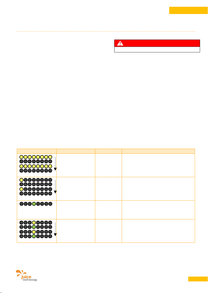
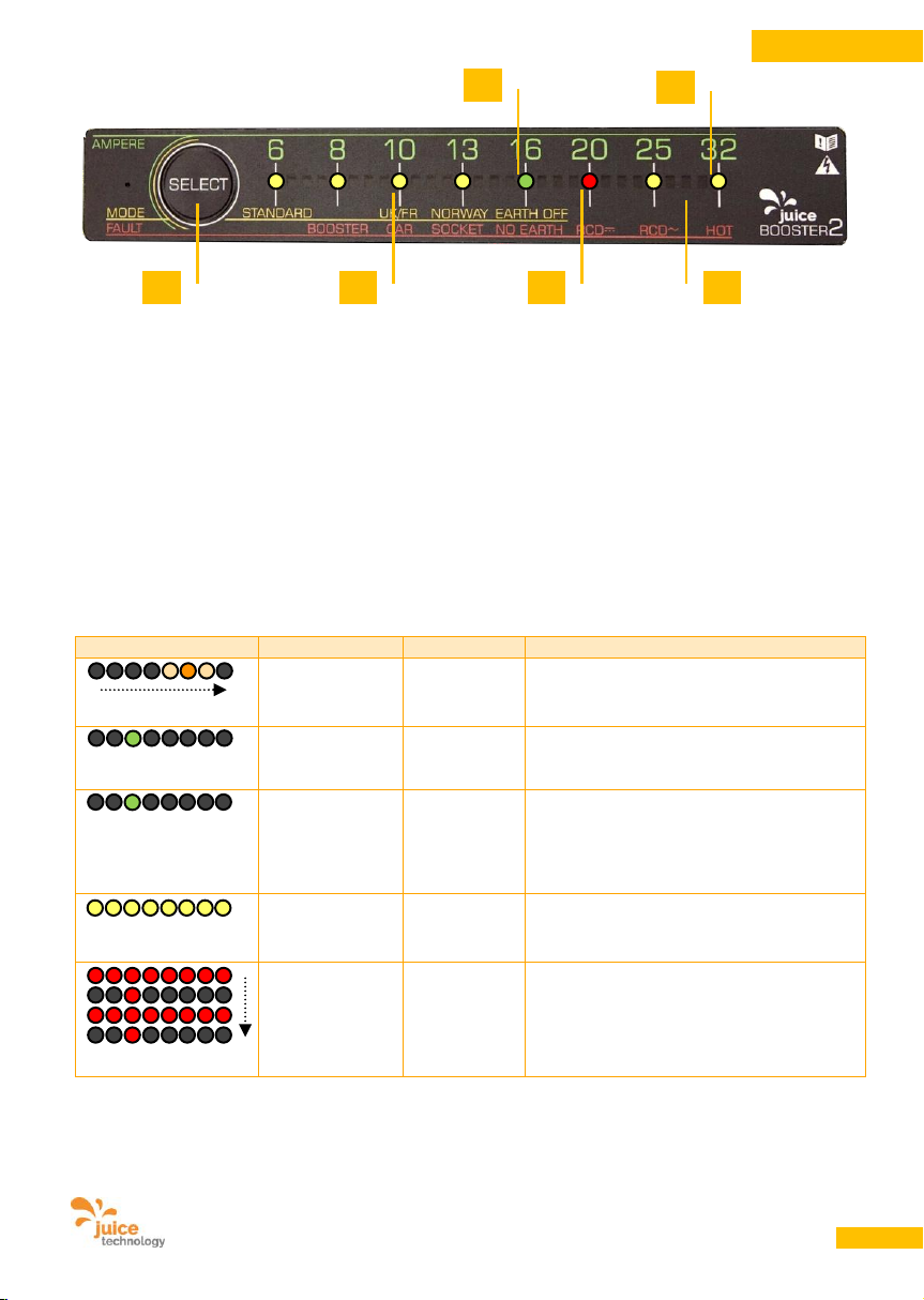
• Beachten Sie folgende Zustandsanzeigen:
Anzeige
Die LED(s)
Dauer
Vorgang
Gelbe LEDs
Alle blinken gelb
(A)
ca. 3 Sek.
Initialisierung des Geräts,
Ladestärke wird durch das Gerät
erkannt
Gelbe LED
Einzelne LED blinkt
gelb
(B)
30 Sek.
Das Gerät zeigt den vorgewählten
Modus (MODE) an*
Grüne LED
Leuchtet grün beim
Ampère-Wert (C)
dauernd
Ampère-Lade-Wert eingestellt, Gerät ist
bereit zum Laden (dieser Zustand wird
auch angezeigt, wenn die Ladung vom
Fahrzeug ordentlich beendet wurde)
Blinkt abwechselnd
gelb und grün beim
Ampère-Wert (B
und C)
30 Sek.
Ampère-Lade-Wert und vorgewählter
Modus liegen auf derselben Position,
deshalb diese Doppelanzeige
Page 18
Benutzerhandbuch JUICE BOOSTER 2 [EL-JB2, EA-JB2] Version 2.00 DE
18
DEUTSCH
13.2. Ladevorgang starten
• Schliessen Sie die Typ 2- oder Typ 1-
Kupplung am Fahrzeug an.
• Der Ladevorgang startet automatisch mit der
ermittelten bzw. manuell reduziert
eingestellten Ladestärke (ausser JUICE
BOOSTER 2 stellt einen Fehler fest).
• Der Druck-Taster (F) zur Wahl der
Ladestärke bzw. des Lademodus kann bis
30 Sekunden nach dem Einstecken des
Fahrzeugs betätigt werden. Danach wird er
deaktiviert. Die Ladestärke und der Lademodus sind dann nicht mehr veränderbar,
solange der JUICE BOOSTER 2 am Fahrzeug eingesteckt ist. Zieht also jemand bei
abgeschlossenem Fahrzeug den Netzstecker
aus und schliesst ihn wieder an, lässt sich
die Ladestärke nicht verändern und der
JUICE BOOSTER 2 beginnt selbständig
wieder mit dem Ladevorgang, mit der
gleichen Leistung wie zuvor.
Anzeige
Die LED(s)
Dauer
Vorgang
Oranges
Lauflicht (D)
dauernd
Ladevorgang aktiv
Grüne LED
einzelne LED
leuchtet grün
dauernd
Anzeige der Ladestärke in Ampère
Grüne LED
einzelne LED
leuchtet grün,
KEIN Lauflicht
dauernd
Der Ladevorgang ist entweder noch nicht
gestartet (z.B. weil im Auto die Ladung auf
einen bestimmten Zeitpunkt geplant
wurde) oder aber durch ein ordentliches
Signal vom Fahrzeug beendet worden.
Gelbe LEDs
Alle leuchten
gelb (A)
dauernd
Steckdose ist falsch bzw. vertauscht
verdrahtet.
Rote LEDs
alle blinken rot,
eine einzelne
LED leuchtet rot
auf (E)
abwechselnd
blinkend
Fehlermeldung. Siehe Punkt 15.
Einzelne rot leuchtende LED zeigt den
erkannten Fehler an (rot aufgedruckte
Legende)
* Der Standard-Modus ist für UK, Frankreich, und Norwegen ungeeignet. In diesem Fall
wählen Sie einen anderen Modus (siehe Pkt. 13.4)
A
B
C
D
E
F
Page 19
Benutzerhandbuch JUICE BOOSTER 2 [EL-JB2, EA-JB2] Version 2.00 DE
19
DEUTSCH
WARNUNG
Brandgefahr!
Fehlerhafte oder zu schwach ausgelegte
Zuleitungen und/oder fehlerhafte oder
verbotenerweise überbrückte Absicherung
können zu Brand oder Schwelbrand in der
Leitung oder in der Steckdose führen.
Hinweise:
• Überprüfen Sie während des Ladevorgangs
regelmässig die Temperatur der Steckdosen
und Leitungen. Brechen Sie bei Hitze die
Ladung sofort ab. Hitze ist dann gegeben,
wenn Sie das Kabel oder den Stecker von
Hand nicht mindestens 20 Sekunden
umschlossen halten können.
• Bei besonders alten Strominstallationen kann
es Sinn machen, eine Stufe tiefer als
bezeichnet zu wählen.
• Laden mehrere Leute gleichzeitig an ein und
derselben Sicherung oder sind andere
Verbraucher an dieser Sicherung
angeschlossen, müssen Sie den JUICE
BOOSTER 2 so einstellen, dass die addierte
Gesamt-Ampère-Zahl den Auslösewert des
Lastschützes nicht übersteigt.
13.3. Ladevorgang beenden
Halten Sie nachfolgende Reihenfolge immer
ein:
• Unterbrechen bzw. stoppen Sie den
Ladevorgang im Auto.
• Der JUICE BOOSTER 2 beendet den Lade-
vorgang. Die Kupplung am Auto wird entriegelt. Falls Sie an einer Typ 2-Ladesäule
laden, wird dort der Stecker ebenfalls
entriegelt.
• Entfernen Sie die Typ 2- bzw. Typ 1-
Kupplung am Fahrzeug.
• Entfernen Sie nun den Netzstecker.
• Entkoppeln Sie den JUICE CONNECTOR-
Sicherheitsadapter vom JUICE BOOSTER 2,
wenn gewünscht. Ziehen Sie zu diesem
Zweck den Überwurfring an der JUICE
CONNECTOR-Kupplung zurück und ziehen
Sie die Stecker auseinander.
13.4. Betriebs-Modus (MODE)
auswählen / ändern
Je nach Land, in dem Sie Ihr Elektroauto laden
möchten, benötigen Sie einen anderen
Lademodus. Werksseitig ist der StandardModus voreingestellt. Um den Modus zu ändern
gehen Sie folgendermassen vor:
• Betätigen Sie nach dem netzseitigen
einstecken – bevor Sie am Fahrzeug
einstecken oder bis 30 Sekunden danach –
die SELECT-Drucktaste (F) 5 Sekunden lang,
bis alle LEDs gelb aufblinken. Danach blinkt
nur noch eine LED gelb. Sie zeigt den aktuell
eingestellten Modus an.
• Drücken Sie danach die SELECT-Taste
einzeln bis zum gewünschten Modus
gemäss nachfolgendem Schema. Nach ca. 5
Sek. wird der ausgewählte Modus
automatisch gespeichert.
• Die Modi und deren Verwendung finden Sie
umseitig:
Page 20
Benutzerhandbuch JUICE BOOSTER 2 [EL-JB2, EA-JB2] Version 2.00 DE
20
DEUTSCH
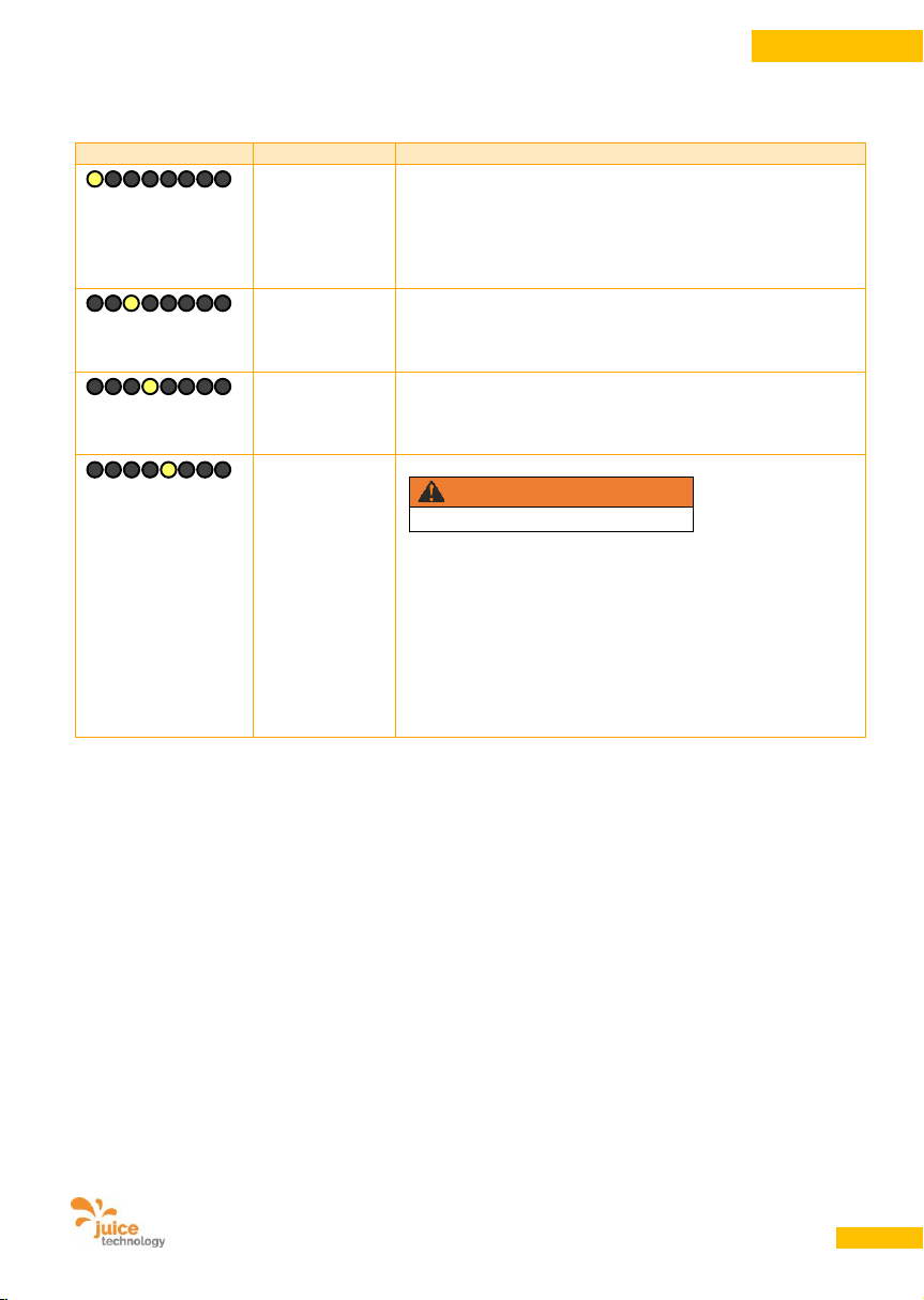
Anzeige
Die LED
Verwendung
Gelbe LED
auf Position
STANDARD
Alle Länder, jedoch ohne
- UK und alle anderen Länder mit Commonwealth-Stecker
(BS 1363, UK-Haushaltstecker)
- Frankreich
- Norwegen
Gelbe LED
auf Position
UK/FR
Wählen Sie diesen Modus zwingend zum Laden im United
Kingdom und in Frankreich (begrenzt den Schuko-Stecker
auf 10 A bzw. 8 A /14 A für GreenUp).
Gelbe LED
auf Position
NORWAY
Wählen Sie diesen Modus zwingend und ausschliesslich
zum Laden in Norwegen (stellt das Gerät ein für die Nutzung
in erdungsfreien IT-Netzen).
Gelbe LED
auf Position
EARTH OFF
Geräteinterne Erdleiterüberwachung abschalten.
WARNUNG
Lebensgefahr!
Dieser Modus darf nur verwendet werden, wenn Sie sich
dahingehend versichert haben, dass die Elektroinstallation
und die Erdung korrekt angeschlossen ist.
(Durch Schieflasten oder andere Unzulänglichkeiten im
Netz kann es vorkommen, dass die Erdleiterüberwachung
eine Unregelmässigkeit bei der Erdung erkennt, obwohl
diese korrekt angeschlossen ist. Dieser Umstand ist
technisch bedingt nicht anders lösbar. Diese Situation
wurde u.a. wiederholt in Italien beobachtet.)
13.5. Reduktion der Ladestärke
• Betätigen Sie die SELECT-Taste – bevor Sie
die Kupplung im Auto einstecken oder bis 30
Sekunden danach.
• Die grüne LED beginnt zu blinken und
signalisiert damit Veränderungsbereitschaft.
Drücken Sie die SELECT-Taste so oft, bis die
Leuchtdiode bei der gewünschten AmpèreStärke steht.
• Durch weiteres Drücken nach der Position 6
A springt die LED wieder auf den durch den
jeweils eingesetzten Adapter definierten
Höchstwert.
• Es empfiehlt sich bei alten Installationen und
bei Dauerbezug die Ladestärke jeweils zu
reduzieren. Dies kann auch nötig sein, wenn
mehrere E-Fahrer an gemeinsam
abgesicherten Dosen laden oder im Fall,
dass Dosen mit explizit geringeren AmpèreWerten angeschrieben und abgesichert sind.
13.6. Erhöhung der Ladestärke
• Eine Erhöhung über die vom JUICE
BOOSTER 2 ermittelte Ladestärke ist aus
Sicherheitsgründen nicht möglich.
Page 21
Benutzerhandbuch JUICE BOOSTER 2 [EL-JB2, EA-JB2] Version 2.00 DE
21
DEUTSCH
14. Instandhalten und Reinigen
WARNUNG
Lebensgefahr!
14.1. Reinigung
• Trennen Sie den JUICE BOOSTER 2 vom
Netz.
• Reinigen Sie das Gerät nur aussen.
Verwenden Sie dazu ein weiches, leicht
feuchtes oder antistatisches Tuch.
• Verwenden Sie zum Reinigen keine
Reinigungsmittel und keine chemischen
Substanzen.
Halten Sie die Stecker und Kupplungen,
insbesondere die Kontakte, stets sauber und
trocken.
14.2. Wartung
Das Gerät ist grundsätzlich wartungsfrei.
Beachten Sie, dass Stecker und Kupplungen
hochempfindliche Teile sind, deren Kontakte
stets sauber und trocken gehalten werden
müssen. Korrosion an den Kontakten kann zu
verminderter Funktion, Erhitzung oder Defekt
des Gerätes führen. Feuchte Stecker
austrocknen lassen. Im ungesteckten Zustand
Schutzkappen immer aufsetzen.
14.3. Reparaturarbeiten /
Modifikationen
Reparaturen dürfen ausschliesslich vom
Hersteller durchgeführt werden.
Modifikationen dürfen nur vom Hersteller
durchgeführt werden.
15. Störungen und Fehler
Sollte einer der aufgeführten
Lösungsvorschläge das Problem nicht
beseitigen, wenden Sie sich bitte an den
Kundendienst, siehe Punkt 19.
15.1. Stromausfall / Störungen
• Der JUICE BOOSTER 2 startet nach einem
Stromausfall automatisch erneut mit der zu
Beginn des Ladevorganges eingestellten
Ladestärke.
• Sie können den JUICE BOOSTER 2
zurücksetzen, indem Sie den Strom
abschalten, den Stecker netzseitig abziehen
und erneut einstecken. Ziehen Sie den
Netzstecker nie bei laufendem
Ladevorgang.
Page 22
Benutzerhandbuch JUICE BOOSTER 2 [EL-JB2, EA-JB2] Version 2.00 DE
22
DEUTSCH
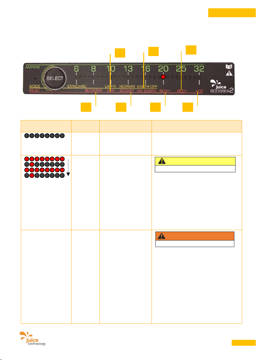
15.2. Fehlermeldungen (Fault)
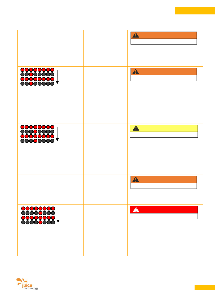
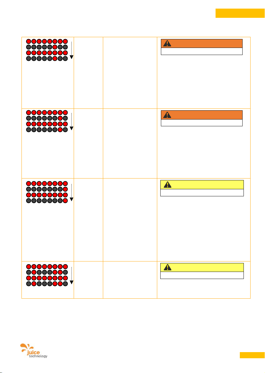
Im Fehlerfall blinken abwechselnd alle LEDs rot, abwechselnd dazu zeigt eine einzelne rote LED den
erkannten Fehler an.
Anzeige
Die
LED(s)
Mögliche Ursache
Massnahme
Alle LEDs
dunkel
Steckdose führt
keinen Strom
Überprüfen Sie, ob alle Stecker
vollständig eingesteckt sind (JUICE
CONNECTOR bis zum Klickgeräusch).
Überprüfen Sie die Hausinstallation.
Rote LED
auf
Position
BOOSTER
(A)
Initialisierungsfehler.
Wird der Strom im
Initialisierungsvorgang
unterbrochen (z.B.
durch einen schlecht
eingesteckten Netzstecker), wird die
Initialisierung im
JUICE BOOSTER 2
nicht korrekt
ausgeführt.
VORSICHT
Beschädigungsgefahr!
Trennen Sie den JUICE BOOSTER 2
vom Fahrzeug und vom Netz. Starten
Sie den Vorgang erneut.
dito
Beim wiederholten
Auftreten in Folge an
verschiedenen Dosen
und mit verschiedenen Adaptern:
Hängendes Relais,
verklebt durch vom
Fahrzeug verursachten Überstrom beim
Abschluss des vorangehenden Ladevorgangs. Wird besonders durch RenaultFahrzeuge verursacht.
WARNUNG
Lebensgefahr!
Versuchen Sie, das Relais zu lösen,
indem Sie den JUICE BOOSTER 2 aus
20 cm Höhe auf den Boden fallen
lassen. Wiederholen Sie diesen Vorgang
drei Mal. Starten Sie dann wie gewohnt
einen neuen Ladevorgang.
Verschwindet der Fehler nicht,
verwenden Sie das Gerät nicht weiter.
Nehmen Sie Kontakt mit dem Hersteller
auf.
A
B
C
D
E
F
G
Page 23
Benutzerhandbuch JUICE BOOSTER 2 [EL-JB2, EA-JB2] Version 2.00 DE
23
DEUTSCH
dito
Beim wiederholten
Auftreten in Folge an
verschiedenen Dosen
und mit verschiedenen Adaptern:
Fehler im Gerät.
WARNUNG
Lebensgefahr!
Verwenden Sie das Gerät nicht weiter.
Nehmen Sie Kontakt mit dem Hersteller
auf.
Rote LED
auf
Position
CAR
(B)
Fehler am Auto.
WARNUNG
Lebensgefahr!
Prüfen Sie Ihr Fahrzeug und die
Steckvorrichtung am Fahrzeug. Wenn
Sie keinen Fehler feststellen, starten Sie
den gesamten Ladevorgang nochmals
ganz von vorn.
Wenn sich der Fehler wiederholt,
nehmen Sie Kontakt mit Ihrer
Autowerkstatt / Ihrem Auto-Händler auf.
Rote LED
auf
Position
SOCKET
(C)
Fehler an der
Steckdose oder
Zuleitung oder nicht
richtig eingestecker
Netzstecker.
VORSICHT
Beschädigungsgefahr!
Prüfen Sie die Installation. Verwenden
Sie gegebenenfalls diese Dose nicht
mehr. Prüfen Sie, ob der Adapter bzw.
der Netzstecker unbeschädigt und
richtig eingesteckt sind. Grenzen Sie den
Fehler ein durch den Einsatz anderer
Adapter und an anderen Steckdosen.
dito
Sensor im
HaushaltsteckerAdapter meldet
Überhitzung.
WARNUNG
Brandgefahr!
Der Ladevorgang wurde kontrolliert
heruntergefahren und zu Ihrer Sicherheit
gestoppt.
Rote LED
auf
Position
NO
EARTH
(D)
Erdleiterüberwachung
meldet Fehler.
Möglicherweise ist an
dieser Dose kein
Erdleiter
angeschlossen.
GEFAHR
Stromschlaggefahr!
Laden Sie nicht an dieser Installation. Es
besteht die Gefahr eines Stromschlages.
Installation von einer Fachkraft prüfen
lassen.
Siehe auch 13.4 – Schieflasten als
Auslöser und Laden in Norwegen.
Page 24
Benutzerhandbuch JUICE BOOSTER 2 [EL-JB2, EA-JB2] Version 2.00 DE
24
DEUTSCH
Rote LED
auf
Position
RCD DC
(E)
FI-Schutzschalter
wurde ausgelöst. Das
Auto sendet
Gleichstrom- (DC)
Fehlerströme zurück
ins Netz.
WARNUNG
Lebensgefahr!
Die Norm verbietet in diesem Fall ein
automatisches Wiedereinschalten.
Trennen Sie den JUICE BOOSTER 2
vom Fahrzeug. Starten Sie den Vorgang
erneut.
Bei wiederholtem Auftreten in Folge:
Lassen Sie Ihr Auto von Ihrer Werkstatt
überprüfen.
Rote LED
auf
Position
RCD AC
(F)
FI-Schutzschalter
wurde ausgelöst. Das
Auto sendet
Wechselstrom- (AC)
Fehlerströme zurück
ins Netz.
WARNUNG
Lebensgefahr!
Die Norm verbietet in diesem Fall ein
automatisches Wiedereinschalten.
Trennen Sie den JUICE BOOSTER 2
vom Fahrzeug. Starten Sie den Vorgang
erneut.
Bei wiederholtem Auftreten in Folge:
Lassen Sie Ihr Auto von Ihrer Werkstatt
überprüfen.
Rote LED
auf
Position
HOT
(G)
Überhitzung des
Ladegeräts.
VORSICHT
Beschädigungsgefahr!
Ladevorgang am Auto unterbrechen.
JUICE BOOSTER 2 abkühlen lassen.
Das Gerät kühlt sich im Fehlerfall auch
automatisch selbst und startet den
Ladevorgang erneut, sobald die
Temperatur des Geräts genügend
gesunken ist. Setzen Sie das Gerät nicht
direkter starker Sonnenbestrahlung aus.
Decken Sie das Gerät nicht ab, um
Wärmestau zu vermeiden.
Rote
LEDs
bei
A, E und F
Initialisierung der
geräteinternen FISchutzfunktion
fehlgeschlagen.
VORSICHT
Beschädigungsgefahr!
Bei wiederholtem Auftreten in Folge:
Nehmen Sie Kontakt mit dem Hersteller
auf und lassen sie das Gerät überprüfen.
Page 25
Benutzerhandbuch JUICE BOOSTER 2 [EL-JB2, EA-JB2] Version 2.00 DE
25
DEUTSCH
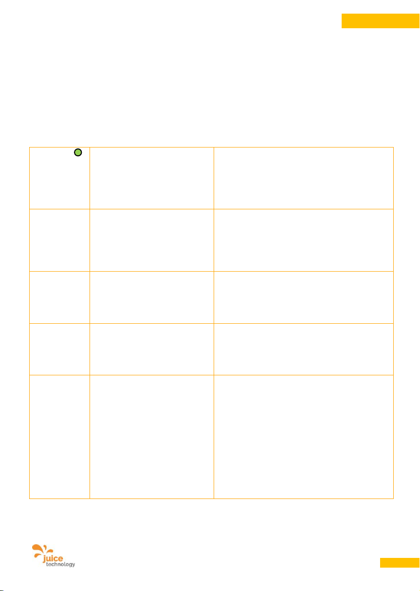
15.3. Spezialfall Renault Zoe
Bekannte Probleme des Fahrzeugs Renault Zoe, besonders häufig bei Modellen mit 43 kW-Lader.
Verlangen Sie von Ihrer Werkstatt ein hardware-technisches Update des Laders, das diese Probleme löst
oder vermindert. Der JUICE BOOSTER 2 wurde im Entwicklungscenter von Renault in Paris-Guyancourt
getestet.
Diese Probleme stehen nicht im Zusammenhang mit dem JUICE BOOSTER 2 sondern treten bei jeder
Ladeinfrastruktur auf. Der JUICE BOOSTER 2 verfügt jedoch über einzigartige spezifische Optimierungen
und Filter, um die Empfindlichkeit des Renault-Onboard-Laders zu mindern.
Grüne LED
leuchtet
dauernd beim
eingestellten
Ampère-Wert
Unterbrechung des
Ladungsvorgangs, der später von
selbst wieder gestartet wird.
Wird keine Fehlermeldung angezeigt, wurde die
Ladung vom Fahrzeug per ordentlichem Befehl
beendet oder pausiert. Dieser Zustand wird vor
allem beobachtet bei der Renault Zoe, die u.a. bei
heisser Batterie den Ladevorgang zeitweilig
stoppt.
Alle LEDs
dunkel
Haussicherung oder der FI (RCD)
in der Hausinstallation löst aus.
Das Fahrzeug hat zuvor mit
einem höheren Ampère-Wert als
am JUICE BOOSTER 2 angezeigt
war, geladen.
Es wurde schon beobachtet, dass die Renault
Zoe die gemäss Norm übermittelten Stromwerte
ignoriert und ein Eigenleben führt.
Ladung startet
nicht oder
bricht ab
Ladeleistung zu tief
Die Renault Zoe bekundet Mühe, bei 3phasiger
Zuleitung unter 13 A und bei 1phasiger Zuleitung
unter 8 A zu laden (siehe auch FahrzeugHandbuch). Der Fehler liegt im Aufbau der
Ladeeinheit des Autos.
Ladung startet
nicht oder
bricht ab
Netzeinflüsse
Die Renault Zoe reagiert teilweise sehr
empfindlich auf Zustände im Stromnetz (z.B.
Einflüsse von anderen unsauberen Verbrauchern
an der gleichen Trafostation, Oberwellen,
Schieflast, Rundsteuersignale etc.).
RCD AC
und/oder RCD
DC lösen
immer wieder
aus
Das Fahrzeug schickt
Fehlerströme ins Netz oder
produziert einen Kurzschluss.
Es kommt vor, dass die Renault Zoe aus
unterschiedlichsten Gründen teilweise
gravierende Fehler produzieren. Auslösend kann,
aber muss nicht, die Netzqualität sein (z. B.
plötzliche Netz-Schieflast oder Verlust einer
Phase).
Diese Fehler werden jedoch immer vom Fahrzeug
produziert, gehen immer von diesem selbst aus
und haben keinen Zusammenhang mit dem
JUICE BOOSTER 2, der gemäss Norm in diesen
Fällen den Ladevorgang zu Ihrer Sicherheit
unterbrechen muss.
Page 26
Benutzerhandbuch JUICE BOOSTER 2 [EL-JB2, EA-JB2] Version 2.00 DE
26
DEUTSCH
15.4. Zurücksetzen von
Fehlermeldungen
Überprüfen Sie zuerst die Fehlermeldung und
stellen Sie sicher, dass Sie den Fehler erkannt
und notiert haben. Unternehmen Sie die
vorstehend empfohlenen Schritte.
GEFAHR
Stromschlaggefahr!
Wenn Sie die Fehlermeldung zurücksetzen und
den Ladevorgang erneut starten wollen, stellen
Sie sicher, dass weder vom Auto, noch von der
Hausinstallation und Zuleitung, noch vom JUICE
BOOSTER 2 eine Gefahr ausgeht. Stecken Sie
das Gerät am Fahrzeug und an der Steckdose
aus, um die Fehlererkennung zurückzusetzen.
Starten Sie dann den Ladevorgang wie gewohnt
erneut.
15.5. Mechanische Bauteile lassen
sich nicht in den Grundzustand
bringen oder Stecker lassen sich
nicht einstecken
• Wenden Sie sich bitte an unser
Servicecenter.
WARNUNG
Lebensgefahr!
• Prüfen Sie die Bestandteile auf
Beschädigungen. Berühren Sie keine
beschädigten Teile und schalten Sie die
Dose stromfrei, bevor Sie das Gerät vom
Netz nehmen.
15.6. Offensichtliche Beschädigung
des JUICE BOOSTER 2 oder
verbundener Kabel
• Verwenden Sie den JUICE BOOSTER 2 nicht
weiter. Trennen Sie wenn nötig das Gerät von
der Stromzufuhr indem Sie den externen FISchalter bzw. die Sicherung auslösen.
WARNUNG
Lebensgefahr!
• Bei unter Strom stehenden Gehäusen und
offenen Kabel besteht Lebensgefahr!
16. Massnahmen bei Unfällen mit elektrischem Strom
1. Auf eigenen Isolationsplatz achten und Übersicht verschaffen. Nichts berühren!
2. Unterbrechen Sie den Stromkreis.
Ziehen des Netzsteckers, Auslösen des FI-Schutzschalters bzw. der Sicherung.
Wenn nötig verunglückte Person mit einem nicht-leitenden Gegenstand (z.B. einer trockenen
Isolierstange wie Holzlatte, Holzstab) von den unter Strom stehenden Teilen trennen.
Page 27

Benutzerhandbuch JUICE BOOSTER 2 [EL-JB2, EA-JB2] Version 2.00 DE
27
DEUTSCH
3. Rettungsdienst / Notarzt rufen. Meldeschema:
Wer meldet?
Was ist passiert?
Wo ist es passiert?
Wie viele sind verletzt / betroffen?
4. Lebensrettende Sofortmassnahmen einleiten:
Bei Bewusstlosigkeit:
Den Verletzten in eine stabile Seitenlage bringen. Diese ist für den Verletzten auch dann
erforderlich, wenn Atmung und Puls in Ordnung sind. Die Atemwege müssen frei sein.
Bei Atem- und Herzstillstand:
Sofortige Mund zu Nase- bzw. Mund-zu-Mund-Beatmung durchführen.
Zusätzliche Herzdruckmassage bei Herzstillstand durchführen (je nach Land nur
durch ausgebildete Ersthelfer).
Grundsätzlich gilt: Jede Person, die Berührung mit elektrischem Strom hatte, soll – auch wenn
vordergründig keine Verletzung eingetreten ist – immer zur ärztlichen Kontrolle gebracht werden. In der
Regel ist eine Überwachung der Herzfunktion für einen Tag notwendig, um das Risiko plötzlicher, unter
Umständen tödlich verlaufender Herzrhythmus-Störungen auszuschliessen.
17. Massnahmen bei Elektrobrand
1. Alarmieren Sie die Feuerwehr. Meldeschema:
Wer meldet?
Was ist passiert?
Wo ist es passiert?
2. Auf Eigenschutz achten. Schon geringe Mengen an Rauchgasen sind lebensgefährlich.
3. Wenn möglich Auslösen des FI-Schutzschalter bzw. Auslösung der Hauptsicherung.
4. Löschen Sie mit einem Feuerlöscher, welcher für das Löschen von Elektrobränden zulässig ist (siehe
Beschriftung auf dem Feuerlöscher). Halten Sie einen Mindestabstand von 1 m ein.
Page 28

Benutzerhandbuch JUICE BOOSTER 2 [EL-JB2, EA-JB2] Version 2.00 DE
28
DEUTSCH
18. Gewährleistung und Garantie
Unsere Produkte unterliegen einer strengen
Qualitätskontrolle. Sollte ein bei uns gekaufter
Artikel dennoch nicht einwandfrei funktionieren,
bedauern wir dies sehr und bitten Sie, sich an
unseren nachfolgend aufgeführten Kundendienst zu wenden. Gerne stehen wir Ihnen
telefonisch oder per E-Mail zur Verfügung.
Zusätzlich zur gesetzlichen Gewährleistung
gewähren wir Ihnen eine Garantie auf alle bei
uns gekauften Artikel nach Massgabe der nachfolgenden Bestimmungen. Ihre gesetzlichen
Rechte werden hierdurch nicht eingeschränkt.
18.1. Gewährleistung
• Die Gewährleistung beträgt 2 Jahre ab
Kaufdatum und ist gesetzlich geregelt.
Gewährleistungsansprüche müssen
unverzüglich nach Kenntniserlangung vom
Defekt innerhalb der Gewährleistungsfrist
geltend gemacht werden.
18.2. Garantiezeit
• Die Garantiezeit beträgt 2 Jahre ab
Kaufdatum. Die Garantie gilt auf dem
Kontinent des Erwerbs und ist als Bring-InGarantie ausgestaltet.
• Während der Garantiezeit werden Geräte, die
aufgrund von Material- und Fabrikationsfehlern Defekte aufweisen, nach unserer
Wahl repariert oder ersetzt. Ausgetauschte
Geräte oder Teile von Geräten gehen in
unser Eigentum über. Die Garantieleistungen
bewirken weder eine Verlängerung der
Garantiezeit, noch setzen sie eine neue
Garantie in Gang.
• Garantieansprüche (wie übrigens auch
Gewährleistungsansprüche) müssen
unverzüglich nach Kenntniserlangung vom
Defekt innerhalb der Garantiezeit geltend
gemacht werden.
18.3. Geltendmachung der Garantie
• Halten Sie folgende Dokumente bereit, sie
sind Grundlage für die Geltendmachung Ihrer
Garantieansprüche:
- Lieferschein (Ihre Garantie gilt ab
Lieferdatum)
- Rechnung (Kaufnachweis)
- Garantieschein mit Geräte-Seriennummer
• Setzen Sie sich bitte per E-Mail, Fax oder
Telefon mit dem Kundendienst (Punkt 19) in
Verbindung. Dieser eröffnet ein GarantieTicket, nimmt Ihre Fehlerbeschreibung auf,
nennt Ihnen die Ticket-Nummer und die
korrekte Einsendeadresse.
• Senden Sie keinesfalls Ihr Gerät ohne
vorherige Kontaktnahme an eines unserer
Lager oder an unseren Rechtssitz, da die
Servicestellen extern liegen. Das Paket würde
auf Ihre Kosten retourniert werden.
• Liegt der Defekt im Rahmen unserer
Garantieleistung, erhalten Sie in
angemessener Frist ein repariertes oder
neues Gerät zurück. In diesem Fall
übernimmt JUICE TECHNOLOGY AG die
Rücksendekosten nach folgenden Ländern:
DE, CH, LI, AT, FR, IT, UK, NL, BE, LU, DK.
18.4. Garantieausschluss
Die Garantieansprüche verfallen bei:
• missbräuchlicher oder unsachgemässer
Behandlung, Bedienung oder Transport
• bei nicht bestimmungsgemässem Gebrauch
• bei Verwendung anderer Adapter oder Kabel
als JUICE-CONNECTOR-Sicherheitsadapter
und -kabel
• Verwendung von Zubehör/Ersatzteilen, die
nicht vom Hersteller empfohlen oder geliefert
wurden
• Trennung der JUICE CONNECTOR-
Sicherheitsadapter oder -kabel unter Last
• Trennung vom Netz unter Last
• Korrosion der Steckerkontakte durch
anhaltende Feuchtigkeit und/oder Nässe
Page 29
Benutzerhandbuch JUICE BOOSTER 2 [EL-JB2, EA-JB2] Version 2.00 DE
29
DEUTSCH
• Eindringen von Flüssigkeiten/Wasser durch
ungeschützte oder ungesteckte Stecker und
Kupplungen sowie durch wasserführende
Zuleitungen
• Nichtbeachtung der Bedienungsanleitung
• Massiven Umwelteinflüssen (Feuchtigkeit,
Hitze, Überspannung, Staub etc.)
• Schäden, verursacht durch vom Fahrzeug
erzeugten Kurzschlüssen oder
Überspannungen
• Einsendung in nicht transportsicherer
Verpackung
• Unfall oder unvorhergesehene Ereignisse
(z.B. Blitz, Wasser, Feuer, höhere Gewalt)
• Nichtbeachtung der für das Gerät geltenden
Sicherheitsvorkehrungen
• Nichtbeachtung der Sicherheits-, Warn- und
Gefahrenhinweise
• Gewaltanwendung (z. B. Schlag, Stoss, Fall,
Überrollen, Quetschung, Zerstörung)
• eigenmächtigen Reparaturversuchen
• Eingriffen, die nicht von der von uns
autorisierten Serviceadresse vorgenommen
wurden
• Modifikationen, die nicht vom Hersteller
durchgeführt wurden
• Öffnen oder Bearbeiten von Gehäusen,
Steckern, Kabeln
Kein Garantieanspruch besteht bei:
• Jeder Form der üblichen Abnützung sowie
der Abnützung von Gehäuse, Gummiteilen,
Kabeln, Kabeltüllen und Steckern.
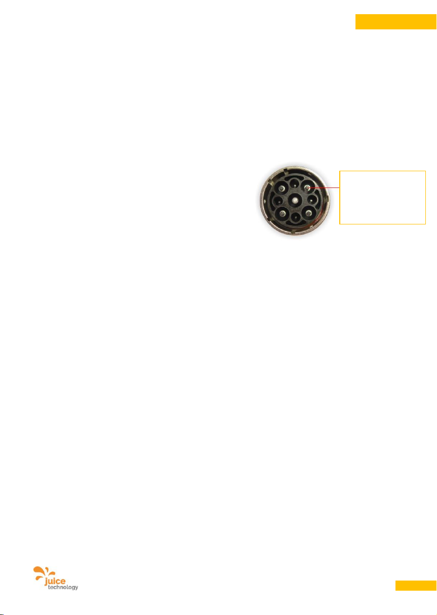
• Wegfall der Berührungsschutzaufsätze am
JUICE CONNECTOR-Stecker. Dies hat
keinen Einfluss auf Sicherheit oder Funktion,
wird von keiner Norm gefordert und ist
deshalb von der Garantie ausgenommen.
18.5. Reparaturen
Vom Garantieumfang nicht (oder nicht mehr)
erfasste Defekte oder Schäden am Gerät
beheben wir gegen Kostenerstattung. Für ein
individuelles Angebot wenden Sie sich bitte an
unseren Kundendienst. Die Versandkosten
gehen zu Ihren Lasten.
Für eingesandte Geräte, die keinen Fehler oder
keinen garantieanspruchsberechtigten Fehler
aufweisen und die der Kunde nicht repariert
haben möchte, wird ein Bearbeitungsanteil
erhoben.
Berührungsschutzaufsatz am JUICE
CONNECTORStecker (m)
Page 30
Benutzerhandbuch JUICE BOOSTER 2 [EL-JB2, EA-JB2] Version 2.00 DE
30
DEUTSCH
19. Servicehinweis / Kundendienst
www.juice-technology.com/service
So geht’s am Schnellsten: Bitte füllen Sie unter dieser Adresse das Online-Formular aus, wenn Sie
technische Fragen haben oder einen Garantieanspruch geltend machen möchten. Wir kümmern uns sofort
darum und unterstützen Sie mit unserem Support.
Kontaktieren Sie in jedem Fall vor einer Einsendung des Produkts unsere Servicestelle per OnlineFormular, Telefon oder E-Mail. Diese wird mit Ihnen das weitere Vorgehen besprechen und Ihnen bei
Bedarf eine Ticket-Nummer sowie die korrekte Zustelladresse mitteilen.
JUICE TECHNOLOGY AG
Kundendienst
20. Hinweise
Änderungen, die dem technischen Entwicklungsfortschritt dienen, sind vorbehalten.
JUICE TECHNOLOGY AG kann nicht gewährleisten, dass alle enthaltenen Forderungen, Vorschriften,
Richtlinien, Spezifikationen und Normen frei von Schutzrechten Dritter sind.
21. Anbieter
JUICE TECHNOLOGY AG
CH-6330 Cham, Switzerland
www.juice-technology.com
E-Mail: [email protected]
Telefon: +41 41 510 02 19
Achtung: Senden Sie keine Geräte oder Waren an diese Adresse. Sowohl Lager wie Servicestelle
liegen an anderen Standorten und sind je Land unterschiedlich.
Warensendungen an diese Adresse werden zu Lasten des Einsenders retourniert. Allfällige Umleitund/oder Zollkosten müssen wir leider weiterbelasten.
Online-Formular: www.juice-technology.com/service
Page 31
Benutzerhandbuch JUICE BOOSTER 2 [EL-JB2, EA-JB2] Version 2.00 DE
31
DEUTSCH
22. Entsorgung / Recycling
Abfalltrennung
Altgeräte dürfen nicht mit dem Hausmüll entsorgt werden.
Rückgabe zur Entsorgung ist bei jedem Elektrohändler möglich.
Machen Sie ausgediente Geräte nach der sachgerechten Demontage (nur durch qualifizierte Fachkräfte)
unbrauchbar, um spätere Unfälle auszuschliessen.
Dieses Gerät ist entsprechend der Richtlinie 2012/19/EU über Elektro- und Elektronik-Altgeräte (waste
electrical and electronic equipment – WEEE) gekennzeichnet. Die Richtlinie gibt den Rahmen für eine EUweit gültige Rücknahme und Verwertung der Altgeräte vor.
Die Entsorgung im normalen Haushaltsabfall ist nicht zulässig. Entsorgen Sie dieses Produkt im
Recyclinghof mit einer getrennten Sammlung für Elektro- und Elektronikgeräte.
Die JUICE BOOSTER 2 besteht aus wiederverwertbaren Materialien. Elektrische und elektronische
Produkte, inklusive Kabel, Stecker und Zubehör müssen gemäss den örtlichen Vorschriften möglicherweise
separat entsorgt werden.
Recycling
Wiederverwertbare Güter
Entsorgen Sie die Verpackung und das Elektrogerät sortenrein. Geben Sie Pappe und Karton zum
Altpapier bzw. Altkarton, Folien in die Werkstoff-Sammlung und entsorgen Sie elektronische Teile beim
Elektrohändler oder einem Recyclinghof der Gemeinde.
Page 32
Benutzerhandbuch JUICE BOOSTER 2 [EL-JB2, EA-JB2] Version 2.00 DE
32
DEUTSCH
Page 33
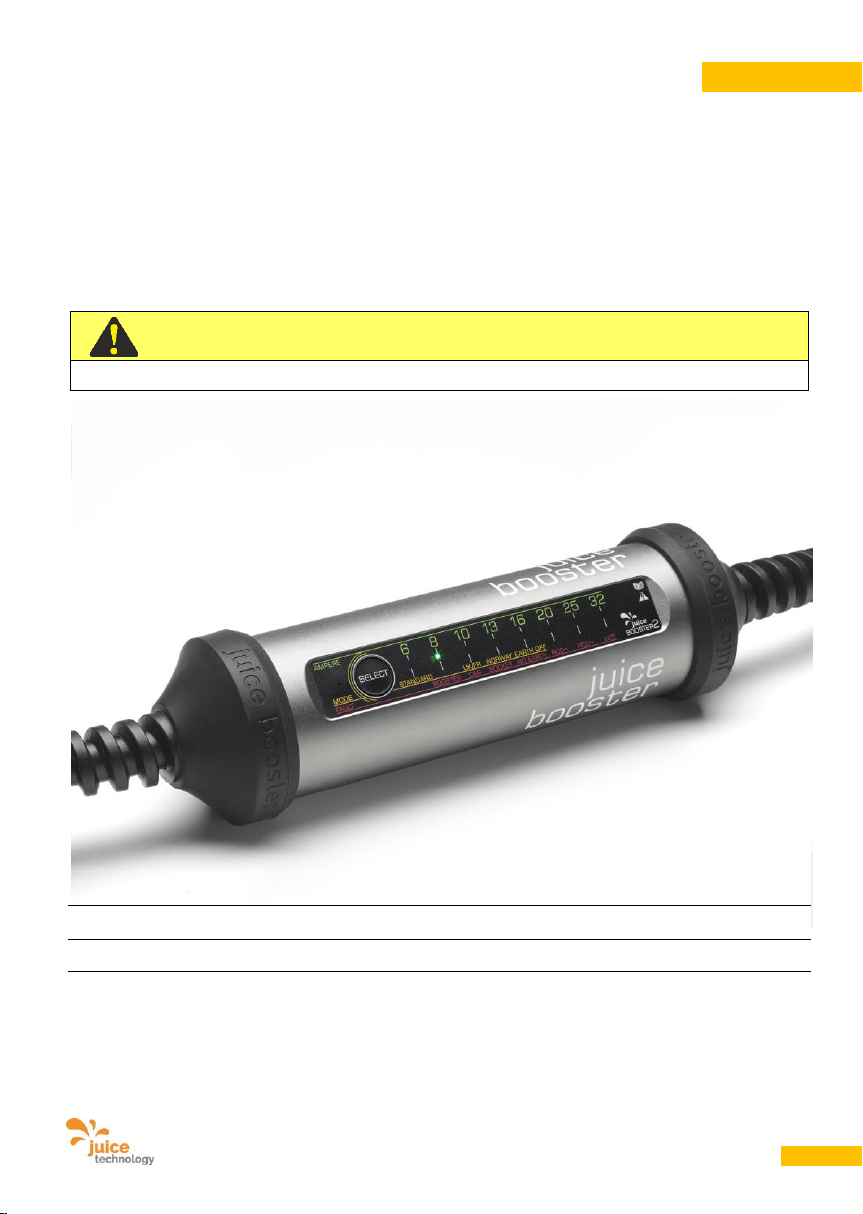
User Manual JUICE BOOSTER 2 [EL-JB2, EA-JB2] Version 2.00 EN
33
ENGLISH
User Manual
JUICE BOOSTER 2
IMPORTANT:
Read this manual before you start using the device!
Portable charger for electric vehicles / Safety Charging Cable
IC-CPD (In-Cable Control and Protection Device for EV charging)
Manual as per DIN EN 82079-1:2013-06; Rel. 2.00 EN
valid for Item Nos.: EL-JB2*, EA-JB2* | P/N JTJB2-EU1R1…, JTJB2-EU1R2…, JTJB2-EU1R3…
Failure to comply with these instructions may result in injury or death, damage
to the device and harm to the environment.
Keep the manual in a safe place for future reference.
ENGLISH
Page 34
User Manual JUICE BOOSTER 2 [EL-JB2, EA-JB2] Version 2.00 EN
34
ENGLISH
1. General
This User Manual is for your JUICE BOOSTER 2.
It contains important information about initial use
and operation.
Read this user manual carefully before you start
using the JUICE BOOSTER 2. It contains
important instructions for the connection, safety
and use of the device.
The User Manual is based on the standards and
rules applicable within the European Union.
Make sure you also comply with the respective
country-specific directives and laws.
Keep this User Manual in a safe place for future
reference and owners. If you pass the JUICE
BOOSTER 2 on to a third party, you must also
pass on this User Manual.
2. Symbol Legend
The following symbols and keywords are used in this manual, on the JUICE BOOSTER 2 or on the
packaging.
DANGER
Mortal Danger!
Indicates a high-risk hazard which, if not avoided,
could result in death, serious injury or major
damage to property.
WARNING
Electric Shock Hazard!
Indicates a medium-risk hazard which, if not
avoided, could result in death, injury or moderate
damage to property.
ATTENTION
Risk of Damage!
Indicates a low-risk hazard which, if not avoided,
could result in minor or moderate injury or
damage to property.
The following symbols are printed on the JUICE BOOSTER and mean:
Declaration of Conformity. Products marked with this symbol meet all applicable
community stipulations by the European Economic Area.
Products marked with this symbol meet the requirements of the EU directive restricting the
use of certain hazardous substances in electrical and electronic equipment.
Page 35
User Manual JUICE BOOSTER 2 [EL-JB2, EA-JB2] Version 2.00 EN
35
ENGLISH
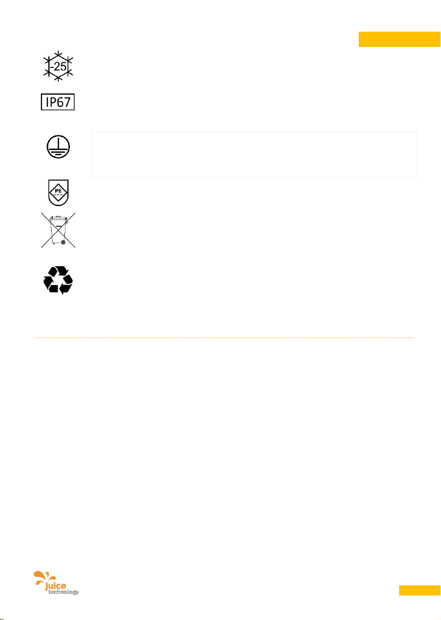
This symbol indicates the lowest possible temperature in °C at which the device may be
operated.
This symbol indicates the protection rating in respect of environmental factors and also the
protection of people against potential hazards while using the device. IP67 means
protected against dust in harmful quantities and immersion in water for short periods.
Protection class I. Products marked with this symbol comply with the DIN EN 61140
standard. In the event of a fault, all metal parts that may be live during operation and
maintenance are connected to an earth conductor.
This symbol indicates that the earth conductor is fixed and permanently connected.
Indicates the disposal method. Waste electrical equipment may not be disposed of with
domestic rubbish. All consumers are obliged to dispose of waste electrical equipment
separately from domestic rubbish, i.e. by handing it in to a community collection point.
Correct disposal prevents any negative impact on the environment.
This is the international symbol for recycling and indicates goods that can be recycled.
Separate packaging by material type before disposal. Card and cardboard with waste
paper/waste cardboard and film in the container for synthetic materials.
3. Table of Contents
1. .............. General ........................................................................................................................................................................................................ 34
2. .............. Symbol Legend........................................................................................................................................................................................... 34
3. .............. Table of Contents ....................................................................................................................................................................................... 35
4. .............. Identification ................................................................................................................................................................................................ 36
5. .............. Intended Use .............................................................................................................................................................................................. 36
6. .............. Safety instructions and hazard warnings ................................................................................................................................................... 37
7. .............. Product description .................................................................................................................................................................................... 39
8. .............. Specifications.............................................................................................................................................................................................. 43
9. .............. Electrical power supply .............................................................................................................................................................................. 44
10. ............ Functions .................................................................................................................................................................................................... 45
11. ............ Preparing the product for use .................................................................................................................................................................... 47
12. ............ Power socket requirements........................................................................................................................................................................ 48
13. ............ Operating instructions ................................................................................................................................................................................ 49
14. ............ Maintenance and cleaning ......................................................................................................................................................................... 53
15. ............ Malfunctions and faults .............................................................................................................................................................................. 53
16. ............ What to do in the event of an accident involving electricity ..................................................................................................................... 58
17. ............ What to do in the event of an electrical fire ............................................................................................................................................... 59
18. ............ Warranty and Guarantee ............................................................................................................................................................................ 60
19. ............ Service information / Customer Services .................................................................................................................................................. 62
20. ............ Notes ........................................................................................................................................................................................................... 62
21. ............ Supplier ....................................................................................................................................................................................................... 62
22. ............ Disposal / Recycling ................................................................................................................................................................................... 63
Page 36
User Manual JUICE BOOSTER 2 [EL-JB2, EA-JB2] Version 2.00 EN
36
ENGLISH
4. Identification
4.1. Product brand and type
Product brand: JUICE BOOSTER 2
Item description: Mobile charger for electric vehicles
Item Nos.: EL-JB2*, EA-JB2*
Product Nos. (P/N): JTJB2-EU1R1…, JTJB2-EU1R2…, JTJB2-EU1R3…
Type IC-CPD (In-Cable Control and Protection Device for EV charging)
4.2. Declaration of conformity with product standards
The JUICE BOOSTER 2 bears the mark. The EU declaration of conformity can be requested at
the following address:
JUICE TECHNOLOGY AG, Gewerbestrasse 7, CH-6330 Cham, Switzerland
(N.B.: Do not send equipment or devices to this address)
5. Intended Use
This charging device is intended for use only with
electric vehicles fitted with a Type 2 connector.
DANGER
Mortal Danger!
Only use the JUICE BOOSTER 2 as described in
the User Manual. Any other use will be deemed
improper and may result in severe injury or
damage to property. The JUICE BOOSTER 2 is not
a toy.
Only use JUICE CONNECTOR safety adapters and
JUICE CONNECTOR safety extension cables from
Juice Technology AG with automatic current
detection. The use of other adapters and/or cables
is prohibited and will be deemed improper use.
Misuse of this nature can result in serious injury
and/or major damage to property.
The manufacturer or dealer will not accept any
liability for damage caused by improper use.
Improper use will make the guarantee void.
Page 37
User Manual JUICE BOOSTER 2 [EL-JB2, EA-JB2] Version 2.00 EN
37
ENGLISH
6. Safety instructions and hazard warnings
DANGER
Electric Shock Hazard!
• Never open the housing! Touching live
parts may be lethal.
• To avoid exposure to electric shocks,
never unplug the connecting plug while it
is under load! This can cause electrical
sparks which may result in excessive wear to
the Juice safety connector and couplings
and reduce their service life. Stop the
charging process in the car first before
disconnecting the plug.
• Never use the device with the cables tangled
or coiled. This can lead to overheating.
• If this happens, never touch the parts with
your hands because you could come into
direct contact with live elements. Mortal
Danger!
• Keep the JUICE BOOSTER 2 away from
explosive vapours or gases. During
operation, the switching mechanisms inside
the JUICE BOOSTER 2 housing may
generate tiny electric sparks which could
ignite an explosion.
• If you discover damage to the JUICE
BOOSTER 2 and/or its components during
operation, disconnect the device from the
mains power immediately by switching off
the main circuit breaker and contact the
service centre. Do not touch any metal parts
and/or cables and/or wet parts.
• Incorrect use of the JUICE BOOSTER 2 may
be fatal!
• Always keep a mobile phone with you for
emergencies.
• Make sure you are aware of how to deal with
accidents involving electricity and what to do
in case of an electrical fire. These points are
described under Points 16 and 17 of this
User Manual.
WARNING
Mortal Danger!
• Never leave packaging material lying around.
Plastic film, plastic bags and other
packaging components could become
hazardous playthings in the hands of
children. There is a danger of suffocation!
• First check the packaging and the device for
possible damage during shipping. Always
inspect the device for defects before
installing and setting it up. Do not operate
the device if you notice irregularities or
damage to the housing, cables, plugs or
sockets.
• Users must comply with their applicable
national regulations regarding the operation,
functional testing, repair and maintenance of
electronic devices.
• Only connect the JUICE BOOSTER 2 to a
correctly installed and properly grounded
power socket.
• If the feed line has no earth conductor and
you operate the JUICE BOOSTER 2 in
“NORWAY” or “EARTH OFF” mode, a subtle
tingling may be felt on the housing as is
typical for the technology. This is caused by
leakage current in the mA range and is both
normal and non-hazardous.
• The power rating of the JUICE BOOSTER 2
must match that of the power supply
network.
• Protect your device from standing water,
excessive dust, corrosive liquids and fumes.
Make sure that the device is not lying in a
Page 38
User Manual JUICE BOOSTER 2 [EL-JB2, EA-JB2] Version 2.00 EN
38
ENGLISH
puddle and that water cannot collect on or
around the device (e.g. if it rains or if there is
melting snow).
• Do not operate the JUICE BOOSTER 2 in the
immediate vicinity of a heat source.
• During the charging process, regularly check
the temperature of the power sockets and
cables. If they are hot, stop charging
immediately. “Hot” is when you cannot keep
your hand around the cable or connector for
more than 20 seconds.
• If the JUICE BOOSTER 2 is exposed to
sunlight for long periods of time or is
operated in a hot environment, the housing
may feel hot. This is a sign of excellent heat
dissipation and is not a problem. In such
cases, hold the device by the cable or the
rubber caps.
• Assembly, installation and repair work on this
installation must be done only by trained
professionals possessing the necessary
know-how, experience and familiarity with the
applicable standards and regulations
enabling them to properly assess for
themselves any potential hazards.
• Any improper usage of the supply line
powering the socket to which the JUICE
BOOSTER 2 is connected, including repair or
installation work thereto, consititutes a
serious danger to the user, for which the
manufacturer is not liable.
• Persons who are not in possession of the
necessary physical, sensory and intellectual
capacity and the experience and know-how
to safely operate the JUICE BOOSTER 2
must only use this device under the
supervision or instruction of a responsible
person.
• Do not allow children, infants, unauthorized
persons or animals to approach the JUICE
BOOSTER 2. Never allow children to play
with the device.
ATTENTION
Risk of Damage!
• The product must only be operated within the
temperature range from -25 °C to +45 °C.
Avoid exposing the JUICE BOOSTER 2 or its
cable to strong sunlight for any length of
time.
• Do not use any sharp or pointed objects to
open the packaging. This could damage the
JUICE BOOSTER 2 or the cables.
• Check for any damage to the packaging, the
device and any parts supplied, e.g. adapters
etc. In the case of damage, do not operate
the JUICE BOOSTER 2. Contact the
manufacturer using the service address
specified on the warranty card – and under
Point 19 of this User Manual.
• Always keep the plug and the JUICE
CONNECTOR connection completely dry.
Plugs can never be waterproof when they are
not plugged in, so always replace the
protective cap when not in use.
NOTE: E-vehicle charging connectors are
high-tech, high-performance parts. Protect
your investment by always keeping the
connectors clean and dry.
Page 39
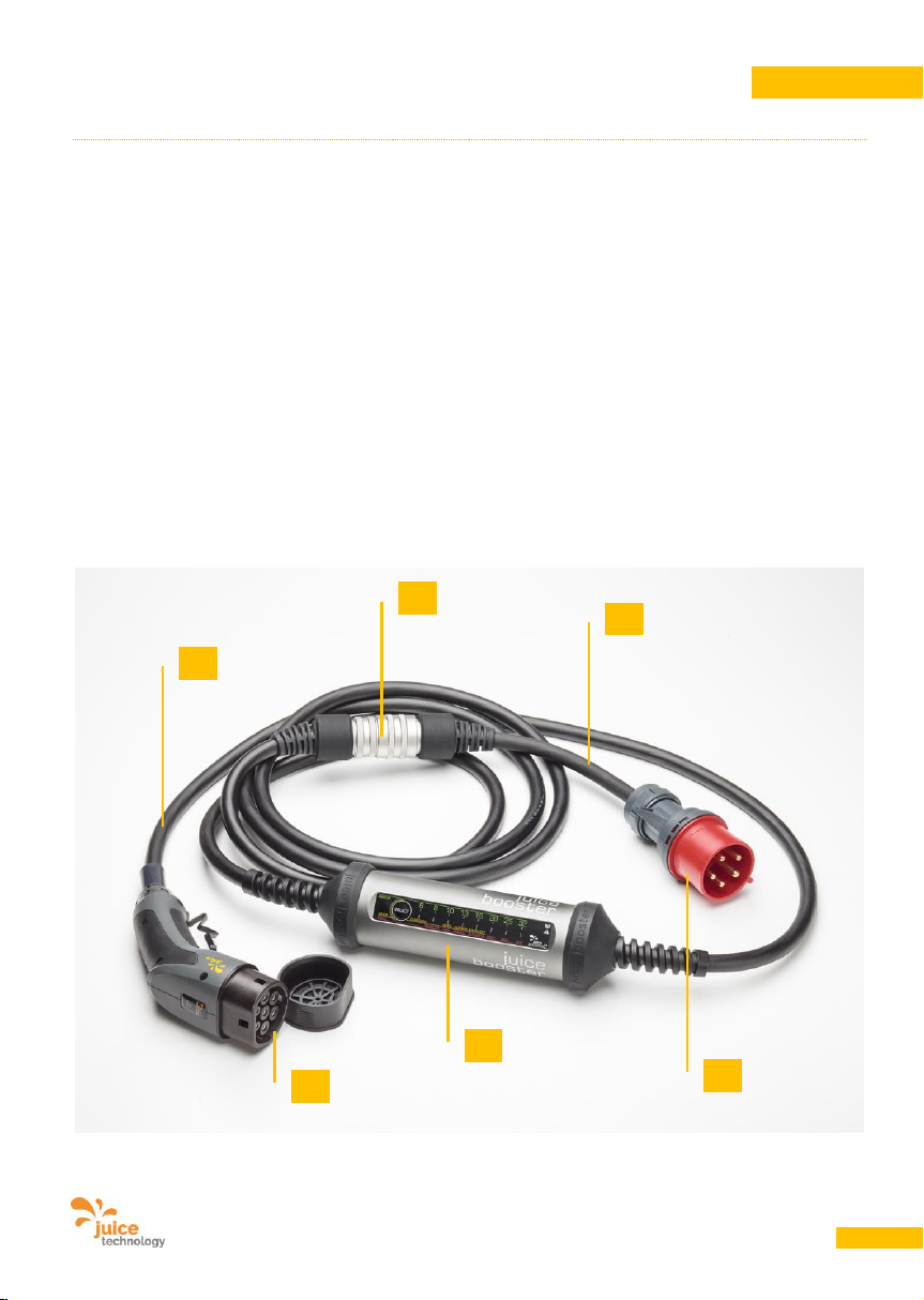
User Manual JUICE BOOSTER 2 [EL-JB2, EA-JB2] Version 2.00 EN
39
ENGLISH
7. Product description
7.1. Scope of supply
Standard equipment:
IC-CPD with the following plugs/connectors:
• Vehicle-end type 2 connector (or type 1 connector)
• Mains-end JUICE CONNECTOR safety connector
• One or more JUICE CONNECTOR safety adapters
Parts:
A. JUICE BOOSTER 2
B. JUICE CONNECTOR safety connector
C. Type 2 connector (for connection to the vehicle)
D. Mains adapter (various adapters available)
E. Mains plug (in this case CEE32 / 400 V, 32 A, 3-phase)
F. 400 V, 32 A, 3-phase heavy-duty cable with control signals
E
B
D
F
C
A
Page 40
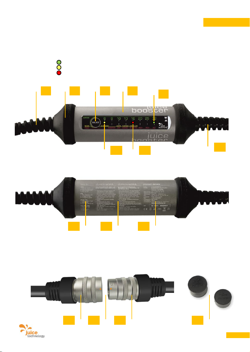
User Manual JUICE BOOSTER 2 [EL-JB2, EA-JB2] Version 2.00 EN
40
ENGLISH
Device front:
G. Mains-end connection with JUICE CONNECTOR safety adapter
H. Housing
I. Non-slip protective rubber parts
J. Charge intensity/mode button
K. Green LED: AMPS (automatically set or individually reduced amp value)
L. Yellow LED: MODE (indicates the selected mode)
M. Red LED: FAULT (may indicate the cause of a fault)
N. Vehicle-end connection cable with type 2 connector (or type 1 alternatively)
Device back:
O. Quick start guide
P. Warnings
Q. Product details and serial number
JUICE CONNECTOR:
R. JUICE CONNECTOR safety connector (m), connects to the JUICE BOOSTER 2
S. JUICE CONNECTOR safety coupling (f) is part of the mains plug adapter
T. Mechanical guides only allow connection in the correct position (orange dots for correct alignment).
Push together until a click is heard. Remove by pulling back the retaining ring (S).
U. Protective caps, supplied with all JUICE CONNECTORs.
G
H
O
P
Q
K
L
J
M
I
N
S
T
R
U
Page 41
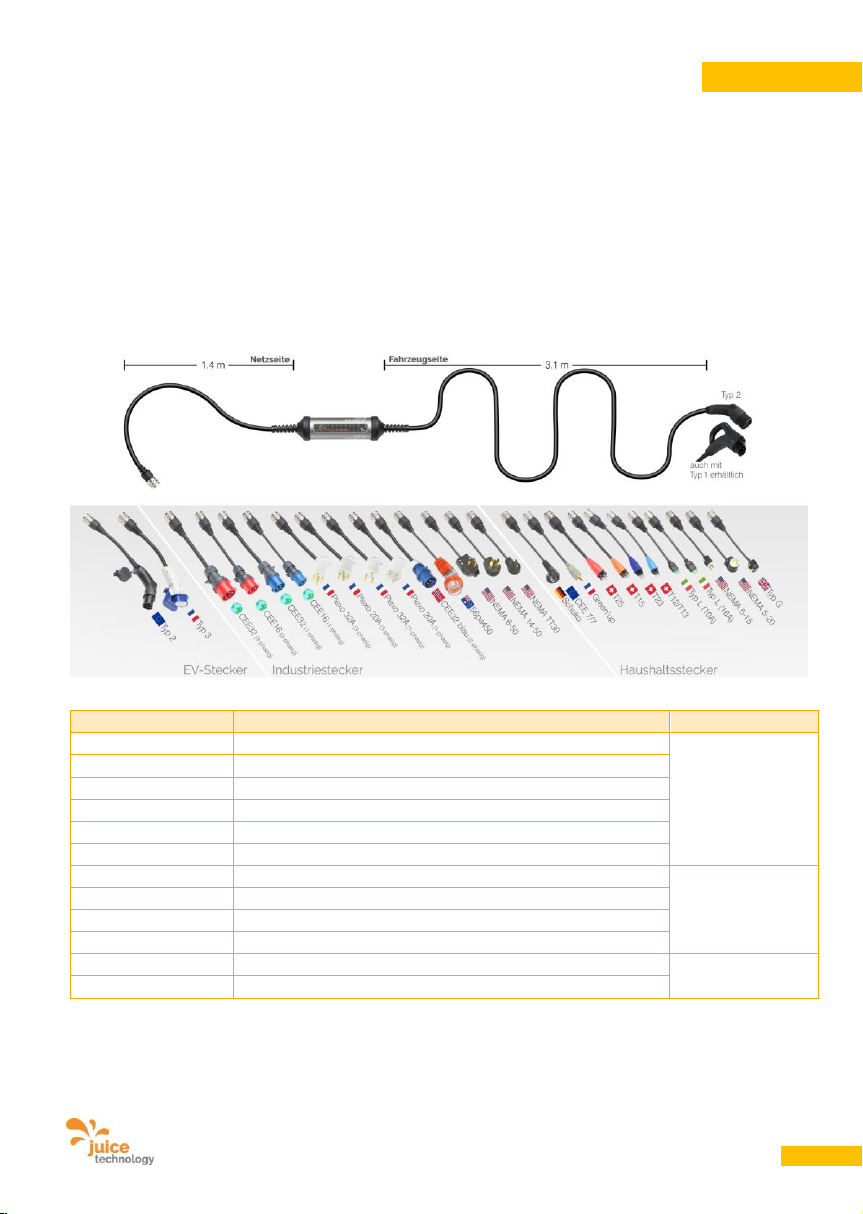
User Manual JUICE BOOSTER 2 [EL-JB2, EA-JB2] Version 2.00 EN
41
ENGLISH
7.2. Optional adapters
JUICE CONNECTOR safety adapters detect the current intensities of the respective sockets used for
charging. The charger automatically sets the appropriate charging intensity.
We recommend various JUICE CONNECTOR safety adapters or adapter sets depending on the country
- adapter sets. These are available separately from JUICE BOOSTER 2 outlets. You will find a selection
listed on the Products page at www.juice-technology.com .
We recommend this type of adapter set for safe and universal connection to all standard power sockets.
Examples of available adapters:
Adapter, e.g.
Use / Description
Class
CEE 7/7 Schuko
EU
Domestic
T13, T23
Switzerland
Type L
Italy
Type G
Commonwealth Countries (BS 1363)
Type AUS
Australia
T15, T25
Switzerland 400 V, 3-phase plug
CEE16 / 230 V
Blue single phase plug (“camping plug”)
Industrial
CEE32 / 230 V
Blue single phase plug (UK, FR)
CEE16 / 400 V
Red 3-phase plug
CEE32 / 400 V
Red 3-phase plug
Type 2 / 32 A
Plug for type 2 sockets
E-mobility
Type 3c
Plug for type 3 sockets (especially FR)
The range of adapters is constantly growing. See www.juice-technology.com/juice-booster for a
complete, up-to-date list of the over 25 adapters available.
Page 42
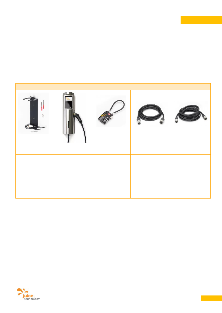
User Manual JUICE BOOSTER 2 [EL-JB2, EA-JB2] Version 2.00 EN
42
ENGLISH
7.3. Optional Extras
A safety lock for the JUICE CONNECTOR safety adapter is available to purchase separately to prevent it
from being disconnected or even stolen by unauthorised third parties.
Optional extras such as a wall bracket for the private and semi-public sector, load management control
unit etc. are available to purchase separately. This means that JUICE BOOSTER 2 can also be used as a
perfect, highly secure and cost-effective wallbox. Good to know: It already has integral DC residual current
detection (RCD Class B), which would otherwise be an expensive extra.
Extras (examples)
Wall mount
Juice Charger 2
Safety lock
Extension cord
5m
Extension cord
10m
Open wall mount,
lock optional.
Including
charging
management
system module,
certified meter.
Payment and
admission
systems optional.
Prevents
effectively
adapters and
extensions from
being plugged
out.
Note: not specified in the Standard, not
CE-compliant therefore. However, as the
connections are waterproof (IP67) and
automatic adapter detection is
transferred, the product is not dangerous
and can be used safely.
Please find the up-to-date list of extras and add-ons here:
www.juice-technology.com/juice-booster
Page 43

User Manual JUICE BOOSTER 2 [EL-JB2, EA-JB2] Version 2.00 EN
43
ENGLISH
8. Specifications
8.1. Construction
• Dimensions of the case Length 265 mm, diameter 70 mm
• Weight 1.0 kg excluding cables, 3.2 kg with cables and plugs
• Material aluminium anodized with rubber end-caps
• Thickness of material 3 mm
• Color Metallic anthracite, black rubber caps and cables
• Protection class IP67 (protects against damaging quantities of dust and immersion
in water for short periods)
• Impact and drop-proof Able to withstand a wheel load of 2,000 kg should you drive over it
by mistake (the rubber casing may burst, and the housing and plug
may be scratched or bent, but live components will not be exposed).
Drop resistant for heights of up to 100 cm
• Temperature range Storage: -30 °C to +60 °C (-22 °F to 140 °F)
Operation: -25 °C to +45 °C (-13 °F to 113 °F)
• Mains-end plug JUICE CONNECTOR safety connector, 400 V, 32 A 3-phase,
highly conductive silver contacts, cable length 1.4 m
• Mains-end adapter Various versions of the JUICE CONNECTOR safety adapter
that can be connected to the JUICE BOOSTER 2 with the
JUICE CONNECTOR safety connector.
The safety adapter automatically tells the device the
maximum obtainable amp value
• Vehicle-end connector Type 2 (EN62196), 400 V, 32 A 3-phase, or
Type 1 (EN62196), 400 V, 32 A single phase,
highly conductive silver contacts, cable length 3.1 m
8.2. Electrical engineering data
• FI residual current, RCD DC 6 mA, AC/DC 30 mA with protective conductor monitoring
circuit breaker
• Input current 230 V, 6 – 32 A (single phase) or 400 V, 6 – 32 A (3-phase) AC
• Output 1.4 – 22.0 kW AC depending on input current
8.3. CE conformity
• Standards IEC 62752, 62196,
61851 Mode 2, 61851 Mode 3 (with type 2/type 3c adapter plug),
EMC, RoHS
Page 44
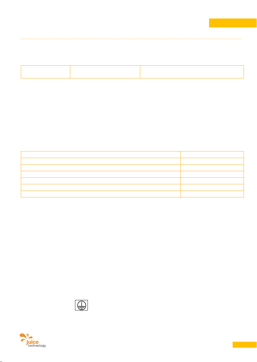
User Manual JUICE BOOSTER 2 [EL-JB2, EA-JB2] Version 2.00 EN
44
ENGLISH
9. Electrical power supply
9.1. Power connection/input voltage
Note the following maximum connection loads:
Item No..:
EL-JB2 / EA-JB2
JUICE BOOSTER 2
32 A AC (3-phase), 400 V * / **
* Single-phase connection at the same amperage rating is possible but will only provide 1/3 of the
charging power in kW.
** Connection is possible with lower amp values. For this, the JUICE BOOSTER 2 must first be
connected at the mains end and the amperage must then be set. The charger can then be
connected to the electric car and the charging process can begin.
9.2. Energy consumption
Power supply at 32 A and 400 V (3-phase AC):
max. 22 kW
Power supply at 16 A and 400 V (3-phase AC):
max. 11 kW
Power supply at 16 A and 230 V (3-phase, charging 2-phase):
max. 7.4 kW
Power supply at 32 A and 230 V (single-phase):
max. 7.4 kW
Power supply at 16 A and 230 V (single-phase):
max. 3.7 kW
Power supply at 8 A and 230 V (single-phase):
max. 1.8 kW
Standby (without charging)
< 1 W
Note on calculating costs: If a power output of 22 kW is used for one hour, then the energy consumption
is 22 kWh. If a kWh (kilowatt hour) costs e.g. EUR 0.30, then 22 kWh cost approximately EUR 6.60.
The cost calculation formulae are as follows:
Amps * 230 V * phases = power in watts (W)
Power in W / 1000 = power in kilowatts (kW)
Power in kW * time in hours * price per kWh = power costs
Standby power usage: At home you can leave JUICE BOOSTER 2 plugged in all year round; it won’t
damage the device at all. The amount of power used on standby is extremely low, working out at around 1
CHF / EUR / USD a year.
9.3. Protection classes
• Protection class I
Page 45
User Manual JUICE BOOSTER 2 [EL-JB2, EA-JB2] Version 2.00 EN
45
ENGLISH
10. Functions
10.1. Basic function
The JUICE BOOSTER 2 is used for recharging
electric vehicles. Using the corresponding
adapters, it is a fully-fledged portable charging
station and also a charging cable to connect to
public charging stations and wallboxes.
The JUICE BOOSTER 2 detects the mains
adapter connected and thus the maximum
permitted charging intensity. As soon as the
cable is connected to an appropriate, functional
outlet and then to the vehicle, and if the vehicle
is ready to be charged, the charging process
begins automatically.
For safety reasons, the JUICE BOOSTER 2
prevents any higher charging intensity from
being set. The charge intensity can be reduced
using the push button however. The JUICE
BOOSTER 2 ignores any button presses during
the charging process. This prevents
unauthorised parties interrupting the charging
process or changing the current.
Since, when locked, the vehicle does not
release the connector even if charging is
interrupted, unauthorised parties are unable to
unplug the vehicle or steal the JUICE BOOSTER
2.
To protect adapters connected using the JUICE
CONNECTOR safety connector from theft, they
can be locked using the safety lock which is
available separately. It makes disconnection
and removal impossible.
10.2. Using type 2/type3c charging
stations with locking mechanism
The connector is locked onto the vehicle and
the charging station before the charging
process begins.
Unlocking is only possible when the charging
process is cancelled by means of a
corresponding command in the electric car or
possibly via app control of the vehicle. The
connector can then be removed from the socket
and the type 2 connector can be removed from
the vehicle.
10.3. Use of domestic and industrial
power sockets (without locking)
The charging process begins automatically as
described in 13.2. The connection to the car is
locked. The connection can be unlocked with a
corresponding command in the car, by
cancelling the charging process.
If unauthorised parties disconnect the cable
from the outlet during the charging process,
when it is plugged in again, charging will
resume automatically at the last detected, or
manually lowered, current.
ATTENTION
Risk of Damage!
Domestic and industrial power sockets do not
have a locking mechanism. During the charging
process, avoid disconnecting the mains-end
connector or the JUICE CONNECTOR! It leads
to flashing loss at the connectors. Furthermore,
the charging electronic and equipment in your
car and your JUICE BOOSTER 2 may become
damaged.
Page 46
User Manual JUICE BOOSTER 2 [EL-JB2, EA-JB2] Version 2.00 EN
46
ENGLISH
10.4. Charging capacity
The following table shows the relationship between charging current and charging time:
Power outlet
Type 2
charging
station
Industrial
power outlet
CEE 32 red
Industrial
power outlet
CEE 16 red
Domestic power
outlet
Schuko Germany
Input power
32 A
32 A
16 A
13 A
Voltage
400 V (3-phase)
400 V (3-phase)
400 V (3phase)
230 V
(single phase)
Power output
max. 22 kW
Max. 22 kW
max. 11 kW
max. 3.0 kW
Charging mode
3 2 2
2
Vehicle
communication
Yes
Yes
Yes
Yes
Charging time*
approx. 1 h
approx. 1 h
approx. 2 h
approx. 6 h
Charge per hour**
approx.
100 - 150 km
approx.
100 - 150 km
approx.
50 - 75 km
approx.
13 - 20 km
* based on an integrated rectifier in the vehicle with an output equivalent to the input power,
and a battery with 22 kWh. With different battery sizes the charging time will change
accordingly.
** depending on the vehicle to be charged and driving style
10.5. Areas of application
At any correctly installed 8 – 32 A, single or
three-phase power socket as well as on
charging stations with a type 2 or type 3 socket.
Please read the notes about setting up the
charging infrastructure in Section 12.
10.6. Installation sites
The housing of the JUICE BOOSTER 2 is
waterproof (IP67), including the buttons. It is
suitable for use outdoors.
Plugs and connectors only reach their IP value
when plugged in correctly. When they are
unplugged, they must be covered with the
protective caps provided to prevent water
getting into the connectors and cables, and
then into the device itself.
The JUICE BOOSTER 2 can be used lying
directly on the ground or wall-mounted by
means of separately available brackets.
Page 47
User Manual JUICE BOOSTER 2 [EL-JB2, EA-JB2] Version 2.00 EN
47
ENGLISH
11. Preparing the product for use
ATTENTION
Risk of Damage!
11.1. Transport and storage
• Stow the packaged JUICE BOOSTER 2
securely during transport to prevent damage.
• Store the JUICE BOOSTER 2 in dry rooms
only.
• When not in use, protect all plugs from dust,
humidity and other influences by using the
protective caps provided. ATTENTION: Plugs
are not waterproof and are susceptible to
external influences when they are not
plugged in.
11.2. Unpacking
• Remove all wrapping film and cardboard.
• After unpacking, inspect the JUICE
BOOSTER 2 and all accessories for any
visible damage. Under no circumstances
should a damaged device be connected. A
damaged JUICE BOOSTER 2 can endanger
your safety!
• Check that all accessories and additionally
supplied parts are present.
• Keep the packaging material out of the reach
of children because it is a potential source of
danger. If the device is to be repacked at a
later stage, this packaging material can be
reused to protect the device from damage
during transport.
11.3. Disposing of the packaging
material safely
The packaging is 100% recyclable and bears
the recycling symbol. Please comply with the
applicable local regulations for disposing of
packaging materials.
Page 48
User Manual JUICE BOOSTER 2 [EL-JB2, EA-JB2] Version 2.00 EN
48
ENGLISH
12. Power socket requirements
12.1. DIN safety rules
DANGER
Electric Shock Hazard!
Modifications to the electrical installation may
only be carried out by qualified professionals. If
you are a qualified electrician, please observe
the 5 safety rules laid down in DIN VDE 0105:
• Disconnect completely
• Secure against re-connection
• Check that power is off at all poles
• Remember to ground yourself before
touching a component to prevent static
discharges!
• Provide protection against adjacent live
parts
These five safety rules should be applied in the
above order before working on electrical
installations. Once the work is completed, they
are lifted in the reverse order.
12.2. Installation and sockets
The sockets in use have to be installed
correctly, especially regarding the quality and
the sequence of phase(s), neutral and PE,
regarding the diameter of the power supply. the
fuse, the RCDs etc.
The socket has to be free of defects and fully
dry.
12.3. Connection to the mains power
supply using adapters and
extension cables
DANGER
Electric Shock Hazard, Fire Hazard!
• Only use JUICE CONNECTOR safety
adapters from Juice Technology AG which
feature automatic current detection.
• Only use extension cables fitted with JUICE
CONNECTOR safety connectors and JUICE
CONNECTOR safety couplings from Juice
Technology AG. Use of other adapters and
extension cables can result in fatal electric
shock and/or fire. Moreover, the guarantee
becomes void.
• Only use correctly installed, properly
grounded power sockets fitted with neutral
conductors. If necessary, check the technical
specifications with the house owner or
building services. Only connect the device if
you are absolutely sure that the power socket
is in good condition.
• In many countries, industrial sockets must be
equipped with a Class A residual current
circuit breaker. JUICE generally recommends
the use of Class A RCDs for all types of
sockets. Please note the regulations in the
country of use, as these always take
precedence.
IMPORTANT: As JUICE BOOSTER 2 already
has integral residual current detection, you
don’t have to allow for the considerable
expense of installing Class B or A (EV) RCD
systems.
Page 49
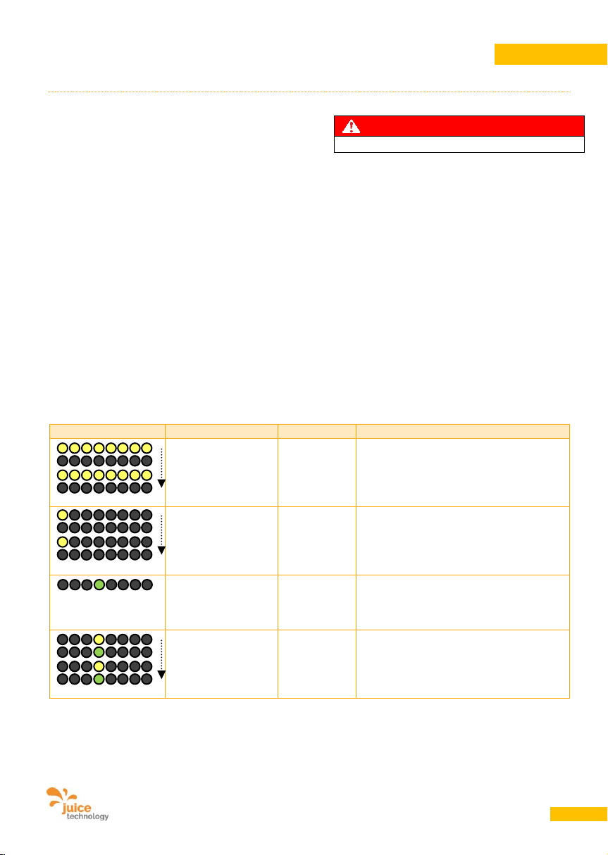
User Manual JUICE BOOSTER 2 [EL-JB2, EA-JB2] Version 2.00 EN
49
ENGLISH
13. Operating instructions
13.1. Starting conditions
• Park your vehicle near a power outlet in
accordance with Point 10.2 or 10.3.
• Ready the JUICE BOOSTER 2.
• Select the correct JUICE CONNECTOR
safety adapter for the power outlet.
• Connect the JUICE CONNECTOR safety
adapter to the JUICE BOOSTER 2.
Mechanical cams only allow connection in
the correct position (orange dots for correct
alignment). Push together until a click is
heard.
• If necessary, insert a JUICE CONNECTOR
safety extension cable between the
BOOSTER and the adapter.
DANGER
Electric Shock Hazard, Fire Hazard!
• Make sure that all cables being used are
fully unwound and that there are no loops.
Failure to do so can result in overheating.
This can cause the insulation to melt and
start a fire.
• Plug the mains adapter into the power outlet.
• Do not use any third party adapters or
extensions, as they may affect the function
and safety of the JUICE BOOSTER 2 and it
would lead to the loss of warranty.
• Take note of the following status indicators:
Display
The LED(s)
Duration
Process
Yellow LEDs
All flashing yellow
(A)
ca. 3 secs.
Device initialization,
charge intensity is being detected by the
device
Yellow LED
A single LED
flashing yellow
(B)
30 secs.
The device displays the selected mode
(MODE)*
Green LED
Light up green at
the amp value (C)
permanent
Amp value set, device is ready to charge
(This status is also displayed once the
vehicle charging has been properly
completed)
Flashes green and
yellow alternately at
the amp value (B
und C)
30 secs.
Amp charge value and selected mode
are in the same position, hence the dual
display
Page 50
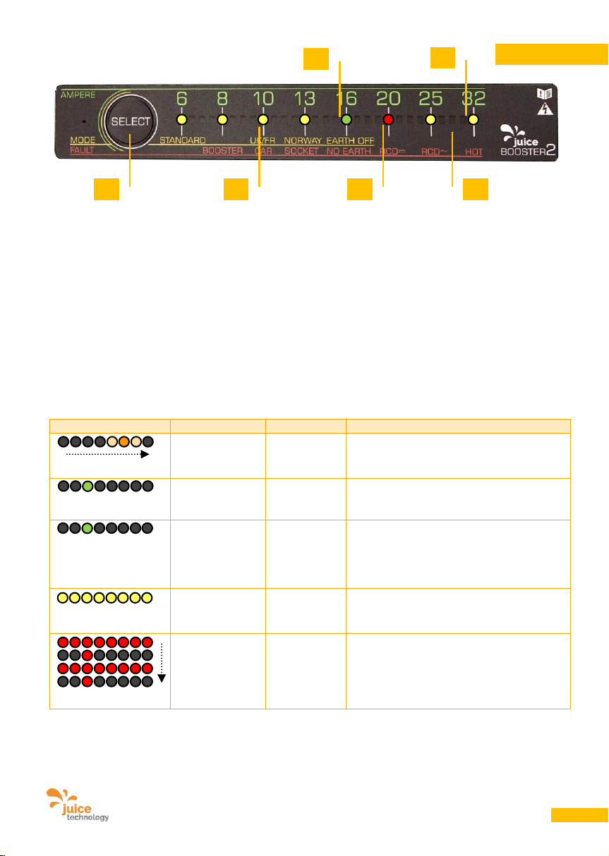
User Manual JUICE BOOSTER 2 [EL-JB2, EA-JB2] Version 2.00 EN
50
ENGLISH
13.2. Starting the charging process
• Connect the type 2 or the type 1 connector to
the vehicle.
• The charging process will begin
automatically at the detected, or manually
reduced, charging intensity (unless JUICE
BOOSTER 2 detects an error).
• The push-button (F) for selecting the charge
intensity and charging mode can be pressed
for up to 30 seconds after the vehicle is
plugged in. After that it will be disabled. It is
then no longer possible to change the
charge intensity or charging mode while the
JUICE BOOSTER 2 is connected to the
vehicle. Therefore, if someone disconnects
the mains while the vehicle is locked and
then plugs it back in again, the charge
intensity does not change, cannot be
changed manually and the JUICE BOOSTER
2 independently resumes the charging
process.
Display
The LED(s)
Duration
Process
Sequential
flashing
orange (D)
permanent
Charging in progress
Green LED
A single LED
lights up green
permanent
Indicates the charge intensity in amps
Green LED
A single LED
lights up green,
NO sequential
flashing lights
permanent
Charging has not yet started (e.g. because
charging has been scheduled for a
specific time) or it has been ended by a
proper signal from the vehicle.
Yellow LEDs
All light up
yellow
permanent
Socket is wired wrong or mixed up.
Red LEDs
All LED flashing
red, one
individual red
indicator at (E)
flashing at
intervals
Error message. See Point 15.
Individual red LEDs indicate the error
detected
* Standard mode is unsuitable for UK, France and Norway. For these countries
select a different mode (see Point 13.4)
A
B
C
D
E
F
Page 51
User Manual JUICE BOOSTER 2 [EL-JB2, EA-JB2] Version 2.00 EN
51
ENGLISH
WARNING
Fire Hazard!
Defective or incorrectly dimensioned cables,
and/or defective or unauthorised fuse bridging
can result in fire or smouldering in the cable or
the outlet.
Notes:
• During the charging process, regularly check
the temperature of the power sockets and
cables. If they are hot, stop charging
immediately. “Hot” is when you cannot keep
your hand around the cable or connector for
more than 20 seconds.
• If the electrical installation is particularly old, it
may make sense to select a power level
below the one suggested.
• If several cars are charging up
simultaneously on the same fuse or if other
devices are connected, it is advisable to
adjust the boxes so that the total amperage
of all devices does not exceed the tripping
threshold of the load-breaker.
13.3. End the charging process
Always follow the sequence below:
• Interrupt or stop the charging process in the
car.
• JUICE BOOSTER 2 will stop the charging
process. The type 2 connector on the vehicle
will be unlocked. If you are charging at a type
2 charging station, the connector will also be
unlocked at that end.
• Remove the type 2 or the type 1 connector
from the vehicle.
• Remove the mains adapter.
• Disconnect the JUICE CONNECTOR safety
adapter from the JUICE BOOSTER 2 if
preferred. To do this, pull the retaining ring
on the JUICE CONNECTOR coupling back
and pull the connectors apart.
13.4. Selecting / changing the
operating mode (MODE)
You may need a different charging mode
depending which country you are charging your
electric car in. The factory setting is Standard
mode. Proceed as follows to change the mode:
• After connecting to the mains – before
plugging into the vehicle or up to 30 seconds
after – hold the SELECT button (F) down for
5 seconds until all the LEDs flash yellow.
Afterwards only one LED will flash yellow.
This indicates the current mode set.
• Press the SELECT button repeatedly until the
desired mode is reached in accordance with
the diagram below. The selected mode will
be saved automatically after approx. 5
seconds.
• Please check out the modes and their use on
the following table:
Page 52
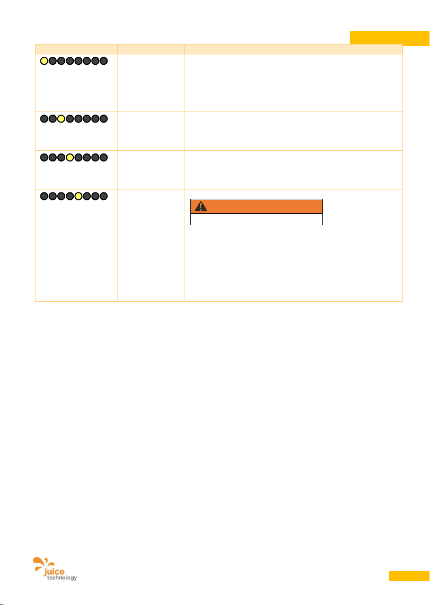
User Manual JUICE BOOSTER 2 [EL-JB2, EA-JB2] Version 2.00 EN
52
ENGLISH
Display
The LED
Use
Yellow LED
at
STANDARD
All countries, except
- UK and all other countries with Commonwealth plug (BS
1636, UK domestic plug)
- France
- Norway
Yellow LED
at
UK/FR
This mode must be selected for charging in the
United Kingdom and France (limits the Schuko plug
to 10 A repectively 8 A /14 A for GreenUp).
Yellow LED
at
NORWAY
This mode, and only this mode, must be selected for
charging in Norway (configures the device for use in
earthing-free IT networks).
Yellow LED
at
EARTH OFF
Disables the device's internal earth conductor monitoring.
WARNING
Mortal Danger!
This mode may only be used once you have checked that
the electrical installation and earthing have been correctly
connected. (Unbalanced loads and other inadequacies in
the grid can result in the earth conductor monitoring
detecting an irregularity with the earthing despite it being
correctly connected. This circumstance can not resolved in
any other way for technical reasons. This situation has been
repeatedly observed in Italy among other places.)
13.5. Reducing the charge intensity
• Press the SELECT button before plugging
the connector into the car or in the 30
seconds afterwards.
• The green LED starts to flash indicating that
the vehicle is ready to charge. Press the
SELECT button as many times as necessary
until the LED is at the desired amperage.
• Pressing the button again after position 6 A
causes the LED to jump back to the
maximum value defined by the respective
adapter in use.
• Reducing the charge intensity is always
recommended for old installations and
continuous operation. This may also be
necessary if multiple e-cars are being
charged at outlets that share fuses or where
the outlets are fused for and specifically state
lower amp values.
13.6. Increasing the charge intensity
• The charging intensity emitted by the JUICE
BOOSTER 2 can not be increased for safety
reasons.
Page 53
User Manual JUICE BOOSTER 2 [EL-JB2, EA-JB2] Version 2.00 EN
53
ENGLISH
14. Maintenance and cleaning
WARNING
Mortal Danger!
14.1. Cleaning
• Disconnect the JUICE BOOSTER 2 from the
mains.
• Only clean the outside of the device. Use a
soft, slightly damp or antistatic cloth. Do not
use detergent or chemical agents to clean it.
• Always keep the connectors and couplings,
particularly the contacts, clean and dry.
If plugs get wet, allow them to dry before
using. Always fit protective caps when not
plugged in.
14.2. Maintenance
The device requires no maintenance. Be aware
that connectors and couplings are highly
sensitive parts. Their contacts must always be
kept clean and dry. Corrosion on the contacts
can lead to impaired function, overheating or
defects in the device.
Let humid or wet plugs dry completely. Always
fit protective caps when not plugged in.
14.3. Repairs/Modifications
Repair work may only be carried out by qualified
professionals.
Only the manufacturer may make modifications.
15. Malfunctions and faults
If one of the outlined procedures does not clear
the problem, please contact Customer Services,
Point 19.
15.1. Power failures/interruptions
• After a power failure, the JUICE BOOSTER 2
automatically restarts the charging process
at the charge intensity set at the beginning of
the process.
• You can reset the JUICE BOOSTER 2 by
switching off the power, disconnecting the
plug from the mains and inserting it back into
the mains. Never pull out the mains adapter
during charging.
Page 54
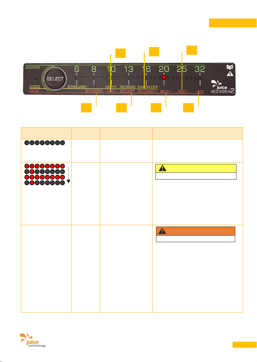
User Manual JUICE BOOSTER 2 [EL-JB2, EA-JB2] Version 2.00 EN
54
ENGLISH
15.2. Fault indications
In case of faults, all of the LEDs will flash red at intervals, alternating with a single red LED indicating the
error detected.
Display
The
LED(s)
Possible cause
Action
All LEDs
off
No current from outlet
Check that all connectors are pushed in
fully (JUICE CONNECTOR until click is
heard).
Check the wiring.
Red LED
at
BOOSTER
(A)
Initialization error. If
the power is
interrupted during the
initialization process
(e.g. by an incorrectly
inserted mains
adapter), the JUICE
BOOSTER 2 will not
initialize correctly.
ATTENTION
Risk of Damage!
Disconnect the JUICE BOOSTER 2 from
the vehicle and the mains. Restart the
process.
ditto
If this occurs
repeatedly and in
succession at
different sockets and
with different
adapters: hanging
relay, stuck due to
surge caused by the
vehicle at the end of
the previous charging
process. This is
particularly common
with Renault cars.
WARNING
Mortal Danger!
Try to release the relay by dropping
JUICE BOOSTER 2 onto the floor from a
height of 20 cm. Repeat three times.
Then start a new charging process as
usual.
If the fault does not disappear, stop
using the device. Contact the
manufacturer.
A
B
C
D
E
F
G
Page 55
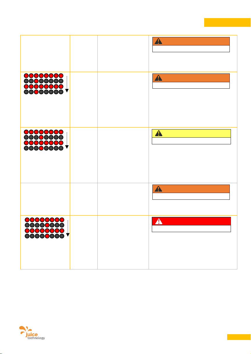
User Manual JUICE BOOSTER 2 [EL-JB2, EA-JB2] Version 2.00 EN
55
ENGLISH
ditto
If this error occurs
repeatedly with
different sockets and
different adapters:
error in device.
WARNING
Mortal Danger!
Stop using the device. Contact the
manufacturer.
Red LED
at
CAR
(B)
Error on the car.
WARNING
Mortal Danger!
Check your vehicle and the vehicle
connection socket. If no defects are
observed, restart the entire charging
process from the beginning.
If the error recurs, contact your garage /
car dealer.
Red LED
at
SOCKET
(C)
Defect in the outlet or
line or incorrectly
connected mains
adapter.
ATTENTION
Risk of Damage!
Check the installation. Where applicable,
stop using this outlet. Check that the
adapter or mains adapter is undamaged
and correctly connected. Narrow the
fault down by using different adapters
and different outlets.
ditto
Sensor in the
household adapterplug reports high
temperature.
WARNING
Electric Fire!
The charging process was controlled
shut down and stopped for your safety.
Red LED
at
NO
EARTH
(D)
Earth conductor
monitoring failed.
There may not be an
earth conductor
connected to this
outlet.
DANGER
Electric Shock Hazard!
Do not charge at this installation. There
is a risk of electric shock. Have the
installation checked by a specialist.
See also 13.4 – Unbalanced loads as
triggers and charging in Norway.
Page 56
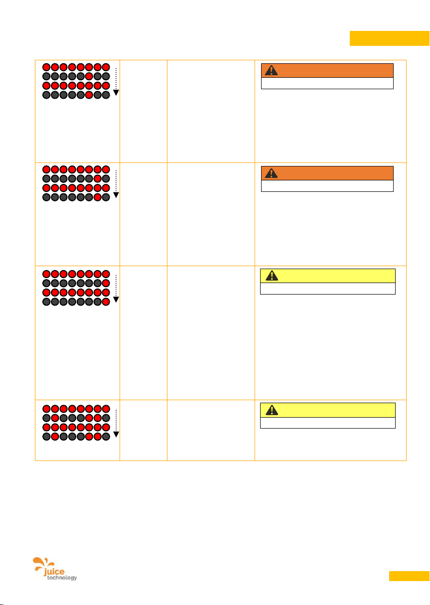
User Manual JUICE BOOSTER 2 [EL-JB2, EA-JB2] Version 2.00 EN
56
ENGLISH
Red LED
at
RCD DC
(E)
FI circuit breaker has
been triggered. The
car is sending
residual direct current
(DC) back into the
mains network.
WARNING
Mortal Danger!
In such cases, the standard prohibits
automatic resetting. Disconnect the
JUICE BOOSTER 2 from the vehicle.
Restart the process.
If this fault occurs repeatedly in
succession: have your vehicle checked
by your garage.
Red LED
at
RCD AC
(F)
FI circuit breaker has
been triggered. The
car is sending
residual alternating
current (AC) back into
the mains network.
WARNING
Mortal Danger!
In such cases, the standard prohibits
automatic resetting. Disconnect the
JUICE BOOSTER 2 from the vehicle.
Restart the process.
If this fault occurs repeatedly in
succession: have your vehicle checked
by your garage.
Red LED
at
HOT
(G)
Charger is
overheating.
ATTENTION
Risk of Damage!
Stop the charging process at the vehicle.
Allow the JUICE BOOSTER 2 to cool
down.
In the event of a fault, the device will also
cool itself down automatically and restart
the charging process as soon as the
device temperature has dropped
sufficiently. Do not expose the device to
strong direct sunlight. Do not cover the
device in order to avoid overheating.
Red LEDs
at
A, E and F
Initialisation of the
RCD protection
function inside the
device has failed.
ATTENTION
Risk of Damage!
If this fault occurs repeatedly in
succession: Contact the manufacturer
and have the device checked.
Page 57

User Manual JUICE BOOSTER 2 [EL-JB2, EA-JB2] Version 2.00 EN
57
ENGLISH
15.3. Special behaviour of Renault Zoe
Known problems with the Renault Zoe vehicle, mostly models with 43 kW charger. Request a technical
update at your garage in order to resolve these problems.
JUICE BOOSTER 2 was tested in Renault’s development centre in Paris-Guyancourt. These problems are
not caused by JUICE BOOSTER 2 and relate to the relevant charging infrastructure. However, JUICE
BOOSTER 2 does incorporate some unique optimized features and filters specifically to reduce the
sensitivity of the Renault onboard charger.
LED glows
green
constantly for
amp value set
Charging process interrupted, will
restart again later by itself.
If no error message is displayed, the charging has
been ended or paused by the vehicle by means of
a normal command. This situation has been
observed in the Renault Zoe in particular which
stops the charging process when the battery gets
hot among other reasons.
All LEDs off
Fuse blown or FI (RCD) triggered
in the building’s distribution
network. The vehicle has
previously charged at a higher
amperage than that displayed on
the JUICE BOOSTER 2.
It has been observed that the Renault Zoe ignores
the default current value and sets its own value.
Charging
does not start
or does abort
Charging performance too low
The Renault Zoe has difficulty charging lower than
13 A with a 3-phase line and lower than 8 A with a
single phase line (as also mentioned in the official
car user’s manual). The fault is in the design of
the car’s charging unit.
Charging
does not start
or does abort
Power network impacts
The Renault Zoe sometimes reacts very nervous
on conditions in the public power network (e.g.
impacts of other unclean users behind the same
transformer station, current fluctuation,
unbalanced current, ripple control signal etc.).
AC RCD
and/or DC
RCD
repeatedly
triggered
The vehicle is sending residual
currents into the mains network
or is producing a short circuit.
Sometimes, for various reasons, the Renault Zoe
produces serious errors. The power supply quality
can, but does not necessarily, act as a trigger
(e.g. sudden unbalanced mains load or loss of a
phase).
The error is always generated by the vehicle
however, always goes away spontaneously and is
in no way related to the JUICE BOOSTER 2 which
complies strictly with the standard and therefore
has to interrupt the charging process for your
safety.
Page 58
User Manual JUICE BOOSTER 2 [EL-JB2, EA-JB2] Version 2.00 EN
58
ENGLISH
15.4. Resetting error messages
Review the error message first and make sure
you have recognised and noted down the error.
Carry out the steps recommended above.
DANGER
Electric Shock Hazard!
If you wish to reset the error message and
restart the charging process, make sure there is
no risk from the car, the wiring system and line
or from the JUICE BOOSTER 2. Disconnect the
device at the vehicle and at the outlet to reset
the fault detection.
Restart the charging process as usual.
15.5. Mechanical components fail to
return to the basic status or
connectors will not plug in
• Please consult our Service Centre.
WARNING
Mortal Danger!
• Check the components for damage. Do not
touch any damaged parts and disconnect
the socket from the power before
disconnecting the device.
15.6. Obvious damage to the JUICE
BOOSTER 2 or attached cables
• Stop using the JUICE BOOSTER 2. If
necessary, disconnect the device from the
power supply by activating the external FI
switch or triggering the fuse.
WARNING
Mortal Danger!
• Mortal danger can result from live housing
parts and bare cables!
16. What to do in the event of an accident involving
electricity
1. Keep yourself insulated at all times and stay aware of the overall situation. Do not touch anything!
2. Turn the electricity off.
Pull out the mains plug, trip the ground fault circuit interrupter (GFCI).
If necessary, move the victim away from the live parts using a non-conductive object (e.g. insulating
pole or rescue rod).
3. Call the emergency services. Call dialogue:
Who is calling?
Page 59

User Manual JUICE BOOSTER 2 [EL-JB2, EA-JB2] Version 2.00 EN
59
ENGLISH
What happened?
Where did it happen?
How many people are injured/affected?
4. Instigate emergency first aid:
If the victim is unconscious:
Move the victim into the recovery position on his/her side. This is necessary even if the
victim’s breathing and pulse appear normal. Keep the victim's air passages free.
If the victim is not breathing and has no pulse:
Perform immediate mouth-to-nose or mouth-to-mouth resuscitation.
Also apply chest compressions if there is no heartbeat (in some countries this
can only be done by trained first-aiders)
The basic rule is: Anyone who has been in contact with electric current should always be checked over by
a doctor – even if they are apparently uninjured. It is generally necessary to monitor their heart rate for a
day to rule out the risk of sudden heart rhythm problems, which could be fatal.
17. What to do in the event of an electrical fire
1. Alert the fire service. Call dialogue:
Who is calling?
What happened?
Where did it happen?
2. Keep yourself safe. Even small quantities of smoke can be lethal!
3. If possible, trip the GFCI or trip the main fuse
4. Extinguish the fire with a fire-extinguisher that is approved for electrical fires (see label on fireextinguisher). Maintain a minimum distance of 1 m.
Page 60

User Manual JUICE BOOSTER 2 [EL-JB2, EA-JB2] Version 2.00 EN
60
ENGLISH
18. Warranty and Guarantee
Our products undergo strict quality control. We
are therefore very sorry if any article you have
purchased from us does not function perfectly
and we ask you to contact our Customer
Services, as detailed below. Please contact us
by phone or e-mail.
In addition to the statutory guarantee, we
provide a warranty for all article purchased from
us in accordance with the following conditions.
This does not affect your common law rights.
18.1. Warranty period
• The warranty is valid for two years from the
date of purchase and is regulated by law.
Warranty claims must be made during the
warranty period as soon as the defect is
identified.
18.2. Guarantee period
• The guarantee period is 2 years from the
date of purchase. The guarantee applies to
the continent on which the device was
purchased and takes the form of a Bring-In
warranty/guarantee.
• During the guarantee period, devices that are
faulty due to material or manufacturing
defects shall either be repaired or replaced,
at our discretion. Exchanged devices or parts
thereof become our property. Exercise of the
guarantee shall not extend the guarantee
period or trigger a new warranty/guarantee.
• Claims under the guarantee (as with
guarantee claims) must be made within the
guarantee period as soon as the defect is
discovered.
18.3. Making a warranty/guarantee
claim
• Have the following documents to hand. They
form the basis for making your claim:
- Delivery note (your warranty runs from the
delivery date)
- Invoice (proof of purchase)
- Warranty certificate with device serial
number
• Please contact our Customer Services (Point
19) by e-mail, fax or telephone. They will
open a warranty ticket, record your fault
description and give you the ticket number
and correct shipping address.
• Please do not send your device to one of
our warehouses or to our headquarters
without first making contact, as our Service
Centres are located elsewhere. The parcel
would be returned to you at your own
expense.
• If the defect is covered by our warranty, you
will receive a new or repaired device within a
reasonable period of time. In such cases,
JUICE TECHNOLOGY AG will cover the
return postage costs to the following
countries: DE, CH, LI, AT, FR, IT, UK, NL, BE,
LU, DK.
18.4. Warranty/guarantee exclusion
Warranty/guarantee claims are void if:
• there is evidence of incorrect or inappropriate
handling, operation or transportation
• the device has been used not as intended
• adapters and cables other than JUICE
CONNECTOR safety adapters and cables
have been used
• accessories/spare parts other than those
recommended or supplied by the
manufacturer have been used
• the JUICE CONNECTOR safety adapter or
cable has been disconnected while under
load
Page 61
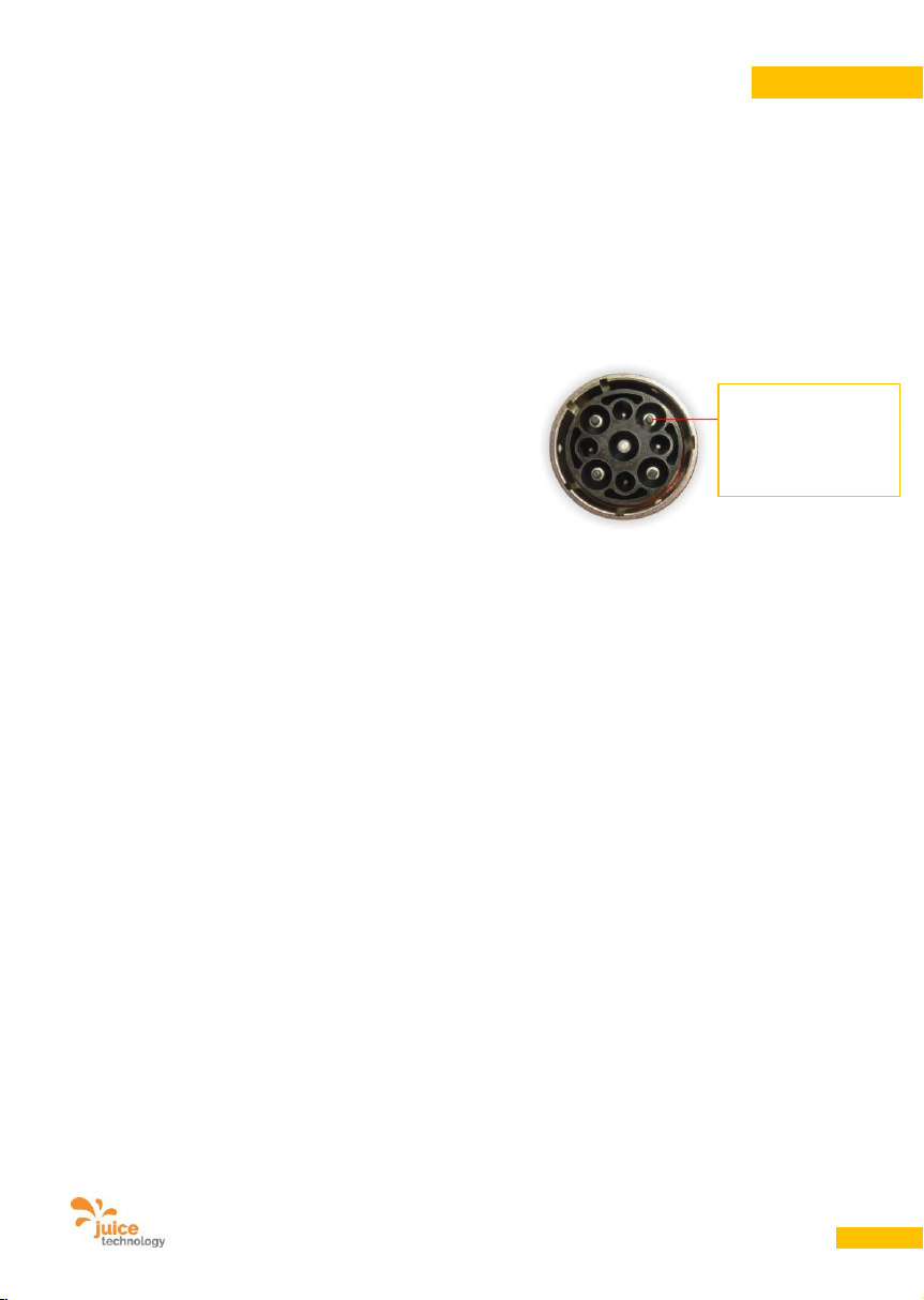
User Manual JUICE BOOSTER 2 [EL-JB2, EA-JB2] Version 2.00 EN
61
ENGLISH
• the mains plug has been disconnected while
under load
• there is corrosion to the connector contacts
due to persistent dampness and/or wetness
• Ingress of water/liquids via unprotected or
unplugged plugs and connectors and
through water pipes.
• the operating instructions have not been
followed
• major environmental factors (moisture, heat,
overvoltage, dust etc.)
• damage caused by short circuits or
overvoltages generated by the vehicle
• the device is returned in inadequately
protective packaging
• accident or unforeseen events (e.g. lightning,
water, fire, force majeure)
• the safety precautions applicable to the
device have not been taken
• safety instructions and hazard warnings have
not been heeded
• force has been used (e.g. the device has
suffered a blow, impact, fall, overrun, crush,
demolition)
• the device has been tampered with by
someone other than our authorised Service
Centre
• you have attempted to repair the device
yourself
• modifications have been made by someone
other than the manufacturer
• the housing, connectors, cables etc. have
been opened or manipulated
The warranty/guarantee does not cover:
• any type of conventional wear and tear or
wear to the housing, rubber parts, cables,
cable sleeves and connectors.
• loss of the protection pins against contact on
the JUICE CONNECTOR plug. This does not
affect safety or function, is not required by
any standard and is therefore excluded from
the warranty.
18.5. Repairs
• We will be happy to repair any defects or
damage to the device not (or no longer)
covered by the warranty in return for a
charge. Please contact our Customer
Services for an individual quote. You are
responsible for shipping costs.
• A processing fee will be charged for shipped
devices that do not have any defects
covered by warranty and that the client
wishes not to have repaired.
Protection pins
against contact on
JUICE
CONNECTOR plug
Page 62
User Manual JUICE BOOSTER 2 [EL-JB2, EA-JB2] Version 2.00 EN
62
ENGLISH
19. Service information / Customer Services
www.juice-technology.com/service
Looking for the fast lane? In case of technical issues or for warranty claims, please fill in our online service
form, address see above.
We will get back to you as soon as possible and assist you with our support.
Always contact our Service Centre by online-form, telephone or e-mail before sending the article to us.
They will discuss with you how to proceed and, if necessary, will give you an ticket number and the
correct delivery address:
JUICE TECHNOLOGY AG
Customer Service
20. Notes
We reserve the right to make changes in the interests of technical improvement.
JUICE TECHNOLOGY AG cannot guarantee that all requirements, specifications and standards are free of
third-party intellectual property rights.
21. Supplier
JUICE TECHNOLOGY AG
CH-6330 Cham, Switzerland
www.juice-technology.com
E-Mail: [email protected]
Telefon: +41 41 510 02 19
Attention: Do not send devices or goods to this address. Warehouses and Service Centres are located
elsewhere and are different for each country.
Goods sent to this address will be returned at the sender’s expense. We regret that we must pass on any
rerouting or customs costs.
Online form: www.juice-technology.com/service
Page 63
User Manual JUICE BOOSTER 2 [EL-JB2, EA-JB2] Version 2.00 EN
63
ENGLISH
22. Disposal / Recycling
Waste separation
Waste electrical equipment may not be disposed of with domestic rubbish.
Return to any electrical retailer for disposal.
After they have been dismantled (only by qualified professionals), obsolete devices must be rendered
unusable to prevent subsequent accidents.
This device is labelled in accordance with Directive 2012/19/EU on Waste Electrical and Electronic
Equipment–WEEE). The Directive provides for the return and recycling of waste equipment throughout the
EU.
It is not permitted to dispose of this equipment with ordinary domestic waste. Dispose of this device at a
recycling centre that collects electrical and electronic equipment separately.
The JUICE BOOSTER 2 is made of recyclable materials. Electrical and electronic products, including
cables, connectors and accessories must be disposed of, separately if possible, in accordance with the
local regulations.
Recycling
Recyclable goods
Separate packaging and the electrical device by material type for disposal. Card and cardboard with waste
paper or waste cardboard, film in the container for synthetic materials and dispose of electronic parts with
an electrical retailer or a community recycling centre.
Page 64
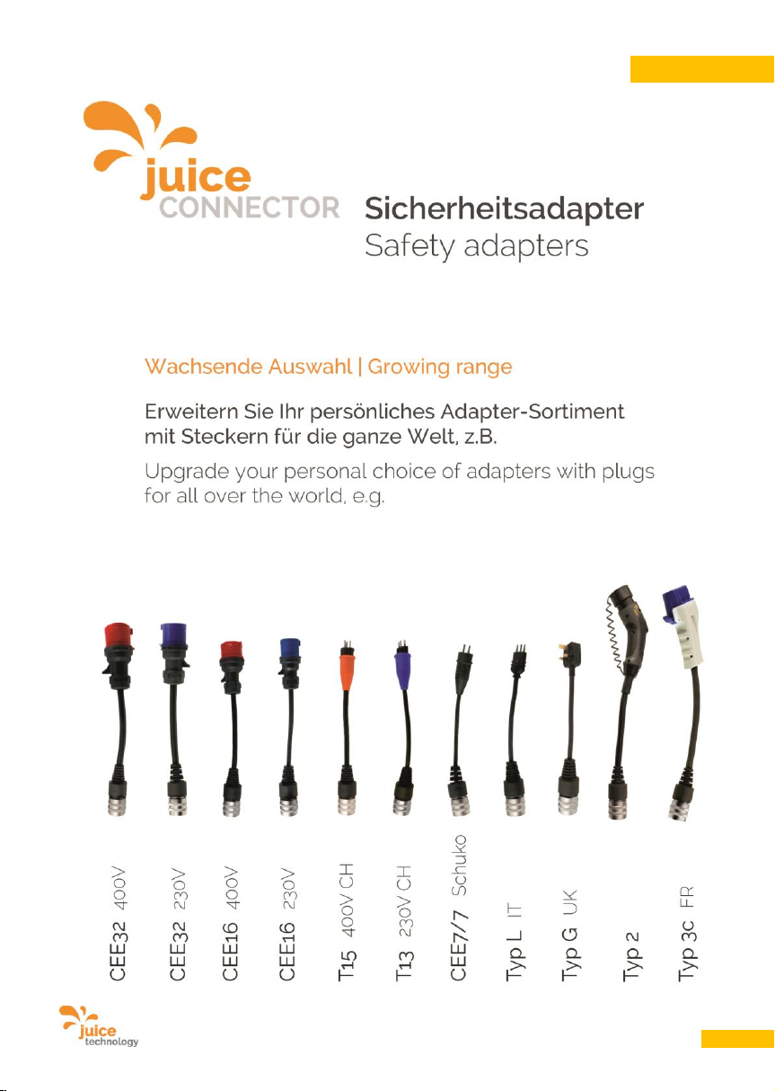
User Manual JUICE BOOSTER 2 [EL-JB2, EA-JB2] Version 2.00 EN
64
ENGLISH
 Loading...