

Judge JSVKIT-A421, JSVKIT-A822 Quick Start Manual

Captured, Caught, Convicted
™
JUDGE
CCTV SURVEILLANCE
Thank you for purchasing a Judge Professional CCTV Surveillance Kit
This Quick Start Guide covers basic setup, installation and use of your surveillance system.
For the full user manual, instructional videos, tips on using your surveillance system &
warranty information, please visit: www.judgecctv.com
Professional CCTV Surveillance System
Quick Start Guide
Models: JSVKIT-A421 (4 channel kit)
JSVKIT-A822 (8 channel kit)
Included Components
JVSKIT-A421: 4 Channel Surveillance Kit JVSKIT-A822: 8 Channel Surveillance Kit
4 Channel HDCVI Digital Video Recorder with 1TB HDD
8 Channel HDCVI Digital Video Recorder with 2TB HDD
4 x 2.0MP 50m Infrared IP67 Mini Domes with mount kits
8 x 2.0MP 50m Infrared IP67 HDCVI Mini Domes with mount kits
1 x CAT5 patch cable, 4 x 18m camera power/video leads
1 x CAT5 patch cable, 8 x 18m camera power/video leads
1 x power splitter, 1 x cameras PSU, 1 x DVR PSU, 1 x USB mouse
2 x power splitter, 2 x cameras PSU, 1 x DVR PSU, 1 x USB mouse
Judge Surveillance Quick Start Guide
2
1. Pre-Installation
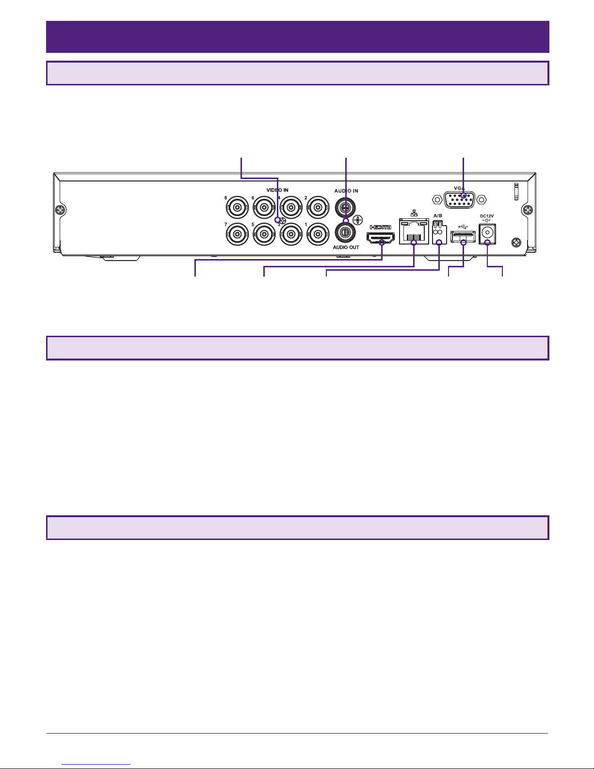
1.1 Understanding your DVR: Rear Panel
1. Connect the cameras to the DVR: Using the 18m video/power cables, connect BNC plugs to the DVR.
2. Connect camera power: Using the 12VDC 3A camera power supply and 4-way power splitter cable.
3. Connect a display: Using an HDMI or VGA cable, connect a monitor or television (not included in kit).
4. Connect the mouse: Connect the USB mouse to the rear USB port, saving the front port for easy USB backup.
5. Connect to your local network: Using the included Ethernet patch cable, connect to your switch or router.
6. Connect DVR power: Using the supplied 12VDC 2A digital video recorder power supply.
Upon activating power, LED lights at the front of the DVR should turn on and the DVR will sound on startup. The
DVR will then run your surveillance user interface. Cameras and LAN / Internet will be detected automatically. This
completes a successful rst boot of your surveillance system and you may begin conguring surveillance cameras.
NOTE: Your DVR model may differ - the 8 channel kit DVR (JVSKIT-A822) is referenced below
Video Inputs: BNC
inputs for camera
video feed
HDMI: HDMI
video output
LAN: Network
(Ethernet) Port
Alarm: External
alarm trigger
input/output
USB: Connect
mouse or
backup device
12VDC 2A:
Power input
Audio: Single channel
RCA input/output for
microphone/loudspeaker
VGA: Video
output for
monitors
1.3 Connecting your DVR and Cameras
The following section will detail connecting the DVR (digital video recorder) and surveillance cameras. It is recommended
that cameras and connections are tested before mounting. If there is no image, an error message or dark screen when
rst connecting cameras, see the Troubleshooting in Section 6 in this guide.
Before connecting your DVR or cameras, please ensure the following safe installation guidelines are adhered to.
• Do not place cords from the DVR where they can be pinched or stepped on.
• Do not place heavy objects on cords, or cover cords with rugs or carpet.
• Do not expose the DVR to excessive heat or moisture.
• Leave at least 50mm of space between the DVR and other objects to allow ample air circulation.
• Never immerse any component in water and do not spray cleaners or solvents on the cameras.
• Shut down and unplug the recorder before cleaning. When cleaning, use a damp, lint-free cloth only.
• Service of your DVR or surveillance cameras should only be handled by qualied technicians.
1.2 Pre-Installation Safety Information
Visit www.judgecctv.com for full user manual and support
3
2. DVR and Camera Conguration
2.1 First Boot and Startup Wizard
After successful connection and boot of your DVR, you will be taken through rst-time setup for your surveillance
system. Here you will congure system security and begin customising your DVR, including setting camera encoding
options, record scheduling, network setup and remote view conguration.
NOTE: Each setting shown in the Startup Wizard can be modied later via the DVR main menu. See the Menu Quick
Guide in Section 6 or see the full user manual for more information.
Following the prompts, complete each section in the Startup Wizard, as detailed below:
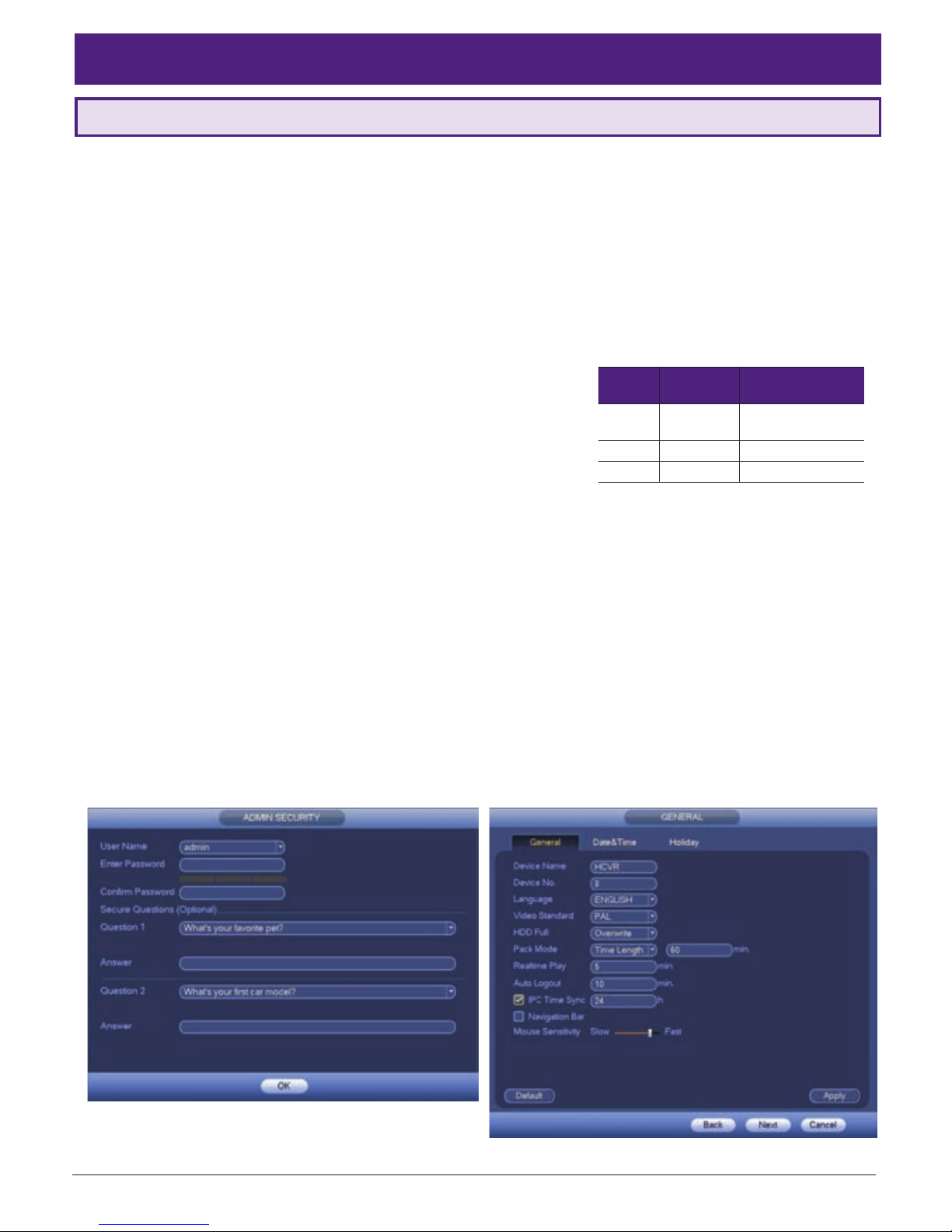
2.1.1 Securing your DVR
Your DVR has 3 permanent users with different levels of access (see Fig.
2.1). In the Startup Wizard, you will be prompted to change the admin user
password. This is to prevent unauthorised remote access via the Internet
to your DVR.
1. Enter a strong admin user password, using letters, numbers & symbols.
2. Conrm your admin user password.
3. Enter security questions/answers to be used if the admin password is
forgotten.
NOTE: Security question answers are case-sensitive, please take note of letter casing when entering answers.
2.1.2 General DVR Setup
After completing the Admin Security section, you will be directed to General setup. Here you can conrm basic options
of your DVR. By default, your DVR is set to overwrite existing footage, have 5 minutes instant playback and logout
automatically after 10 minutes. You can also conrm date & time and set a holiday recording scheduling.
Default settings are adequate to get started, we recommend checking the following:
1. In the General tab, assign a name to your DVR.
2. Switch to the Date & Time tab and conrm correct settings. This directly affects footage search & playback.
User
Default
Password
Privileges
admin admin
Local & remote
admin control
888888 888888 Local admin control
default N/A Local viewing only
Fig. 2.1: Default access settings
Fig. 2.2: Admin Security section
Fig. 2.3: General setup section

Judge Surveillance Quick Start Guide
4
2.1 First Boot and Startup Wizard (continued)
2.1.3 Conguring Network, P2P, and Remote View
NOTE: For the following section, please ensure your network is connected and that your Internet connection is available.
Also, have your Internet connected phone or tablet ready for conguring surveillance remote view.
Network setup will be prompted next, enabling you to connect your DVR to the Internet. First ensure that your DVR
is connected to your switch or router via the included CAT5 cable (detailed in Section 1.3). For the simplest setup we
recommend using DHCP to connect to the Internet. You will then be prompted to congure P2P for remote view on
your device.
Fig. 2.4: Network setup section settings (example only) Fig. 2.5: P2P setup section, with QR codes (example only)
Fig. 2.6: Add Device menu and Live Preview for Android
1. In the Network section, see Fig. 2.4.
2. For the Mode option, select DHCP (Dynamic Host
Conguration Protocol).
3. Should you wish to use a static address, contact
your Internet administrator for details.
4. Click Next to continue.
5. In the P2P (peer to peer) section, see Fig. 2.5.
6. Click Enable to enable P2P remote view.
7. DVR Status should read Online. This indicates an
active Internet connection.
8. Scan the rst QR code, Cell Phone Client, or search
your App Store to download the Easyviewer app.
1. Select the Camera button on the app home screen.
2. Open the application menu
and select the
Device Manager tab
.
3. To add your DVR, select add device
.
4. In the Add Device menu, select P2P.
5. Name your DVR and enter your admin password.
6. In the SN eld, select the QR code icon
.
7. Scan the Device SN QR code shown in Fig. 2.5.
8. Select Start Live Preview to view your cameras.
The following details conguring remote view via the
EasyviewerLite on your Google Android or Apple iOS
device. Depending on your device, menus may function
or appear slightly different to those explained below.
 Loading...