

Page 1
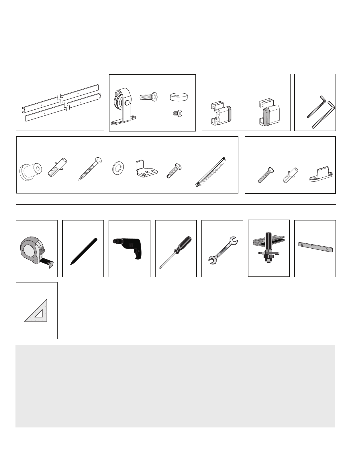
Main Components
x2 Rail
x2 Roller Hanger
x4 Hex Bolts
M6x12mm
3/16" x 15/32"
x2 Anti-jump Block
x2
M4x6mm
5/32" x 1/4"
BARN DOOR HARDWARE KIT
TSQ14BK-6FT+TKM06
INSTALLATION GUIDE
x 2
x1 Right Stopper
x1 Left Stopper
Allen Key
x5 Wall Spacer
x5 1/2" (10mm)
Tools Required
Tape Measure
Speed Square
Anchor Floor
x5 (8mm x 90mm)
5/16" x 3 9/16"
Wall Screw
Pencil
x5 Washers
Cordless Drill
x2 Actuator
X6 Phillips screw
(4.2mm x 19mm)
3/16 " x 25/32"
Phillips Screwdriver
soft cl os e
x2
attac hm en t
Max
l
oad
:
40KGS
Wrench level
x2 (4.2mm x 25mm)
3/16" x 1"
Floor Screws
1/4"
Mortise Router Head
Required for
Floor-Mounted Door
Guide InstallationAllen
x2 5/16"(8mm)
Floor Anchor
x1 Internal
Floor -Mounted
Door Guide
IMPORTANT: BEFORE YOU BEGIN
IF INSTALLING DIRECTLY INTO A NON-CONCRETE WALL, DO NOT ATTEMPT TO INSTALL THE RAIL SOLELY TO THE
DRYWALL OR ANY WALL SURFACE AS THIS MAY NOT SUPPORT THE WEIGHT OF THE RAIL AND MOUNTED DOOR.
THE RAIL MUST BE INSTALLED ONTO A PIECE OF SOLID WOOD BLOCKING ( ) USING MOUNTING PACKAGE NOT INCLUDED
SCREWS ( ). ENSURE THE SOLID WOOD BLOCKING IS SECURED INTO THE STRUCTURAL PACKAGE NOT INCLUDED
SURFACE. USE A STUD FINDER WHERE NECESSARY TO LOCATE STUDS AND SECURE SAFELY. TYPICAL SOLID WOOD
BLOCKING SHOULD BE 81 3/4" x 5 1/2" x 7/8".
NOTE, SEPARATE BOLTS ARE PROVIDED FOR 1 3/8" DOORS AND LONGER BOLTS PROVIDED FOR 1 3/4" DOORS. IF
INSTALLING WITH THE INTERNAL FLOOR-MOUNTED DOOR GUIDE, THE DOOR MUST BE MORTISED 1/4" WIDE X 3/4"
DEEP CENTRALLY.
Page 2
1
2
4
2
3
4
F~it door panel width:9 27/32''~11 13/16''
BARN DOOR HARDWARE KIT
TSQ14BK-6FT+TKM06
INSTALLATION GUIDE
35 63/64''(914mm)
84 1/64''(2134mm)
1 9/16''(40mm)
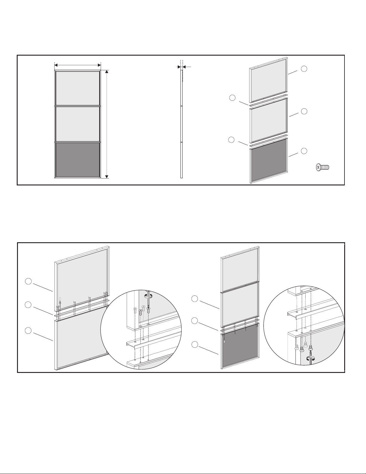
Step 1. Door Preparation
The door is divided into three parts: upper, middle and lower parts ①②③.
Please connect them by connectors ④, and fixed with 13/64 x '' screws'' 35/64
1
4
2
4
3
13/6 4'' x35 /64 "
M5x14(x24)
x12
x12
Page 3
BARN DOOR HARDWARE KIT
TSQ14BK-6FT+TKM06
INSTALLATION GUIDE
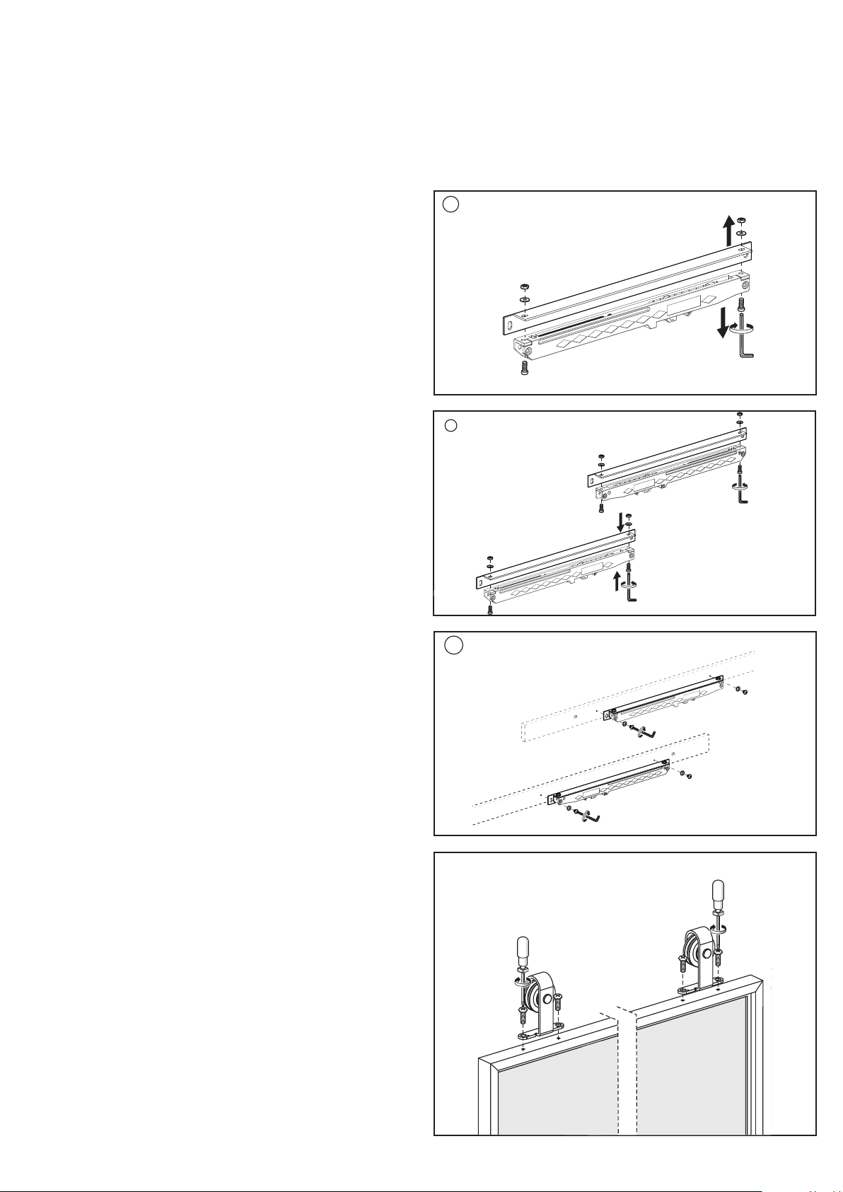
Step 2.Soft Close Installation
Unscrew the screw with a wrench firstly.Change the soft
closes to the correct direction, then tighten and install
them on the rail.
1
M
ax
l
oad
:40KGS
2
M
ax
l
oad
:
Left
l
oad
:
40KGS
40KGS
Right
M
ax
Step 3. Door Preparation – Strap Installation
Install the rollers on the reserved hole of the top of
door by 3/16''x15/32'' screw.
3
M
ax l
oad
:
40KGS
Right
M
ax
l
oad
:
40KGS
Left
Page 4
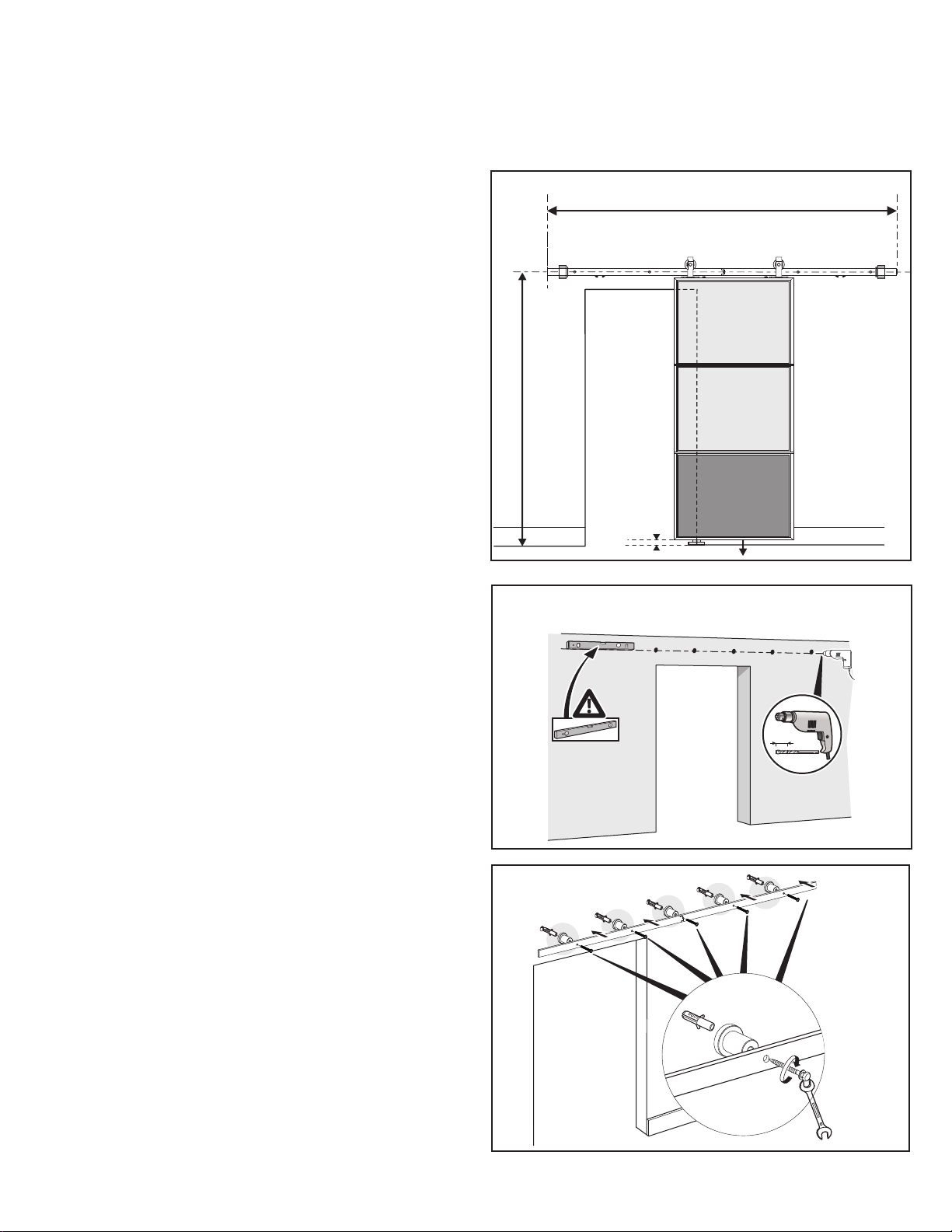
Step 4. CONCRETE Wall Preparation1
Position the rail by measuring up from the door height (H)
+ 1 11/16" to the centre of the track. Also ensure a gap of
3/8" - 1/2" at the bottom. Ensure the rail is level and leave
a minimum of 2" from the end of the rail to the side of the
opening.
If installing with an opening for 80" standard door size,
remove the top trim and cut the side trim horizontally along
the height of the opening.
BARN DOOR HARDWARE KIT
TSQ14BK-6FT+TKM06
INSTALLATION GUIDE
72 3/6"(1830mm)
Step 5. CONCRETE Wall Preparation2
Position the rail in place ensuring that it is level, mark the
holes on the rail using a pencil and pre-drill 25/64" holes
into the concrete.
Step 6. CONCRETE Rail Installation
When installing directly into concrete, align the spacers to
holes,insert using the provided anchors and hex bolts (with
washers).Ensure to un-screw to separate the hex bolt and
anchor to install correctly, securing with a wrench.
Door Height + 1 11/16"(43mm)
25/64"(10mm)1/2"(12.7mm)
Gap under
the door
1 31/32"
(50mm)
25/64"
(10mm)
x5
(X5)
Page 5
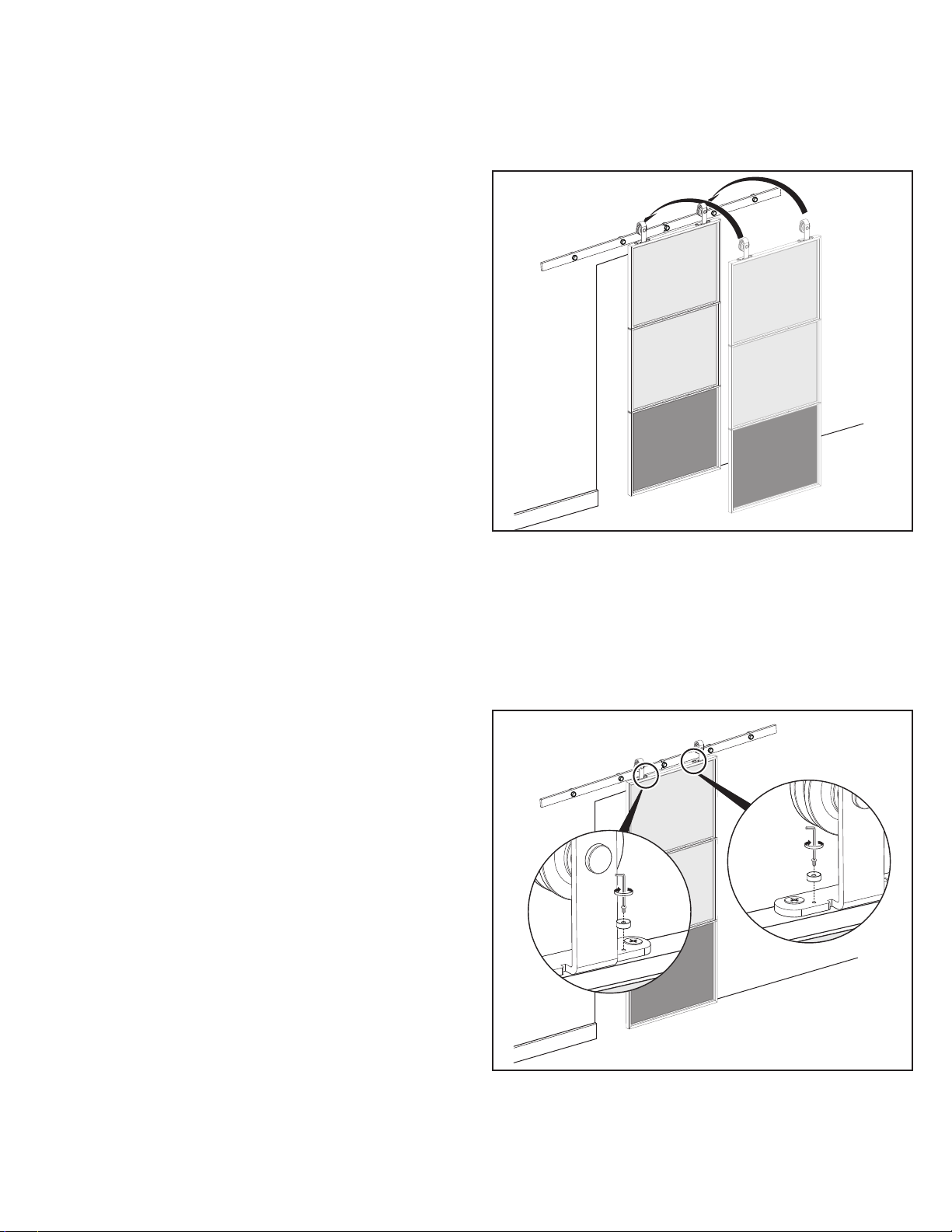
Step 7. Hanging the Door
Place the assembled door onto the secured rail and tighten
BARN DOOR HARDWARE KIT
TSQ14BK-6FT+TKM06
INSTALLATION GUIDE
Step 8. Door Preparation - Anti-jump block
Installation
Install the anti-jump on the rollers by 5/32'' 1/4'' screw to x
protect the door from touching the rail when sliding the door.
Page 6
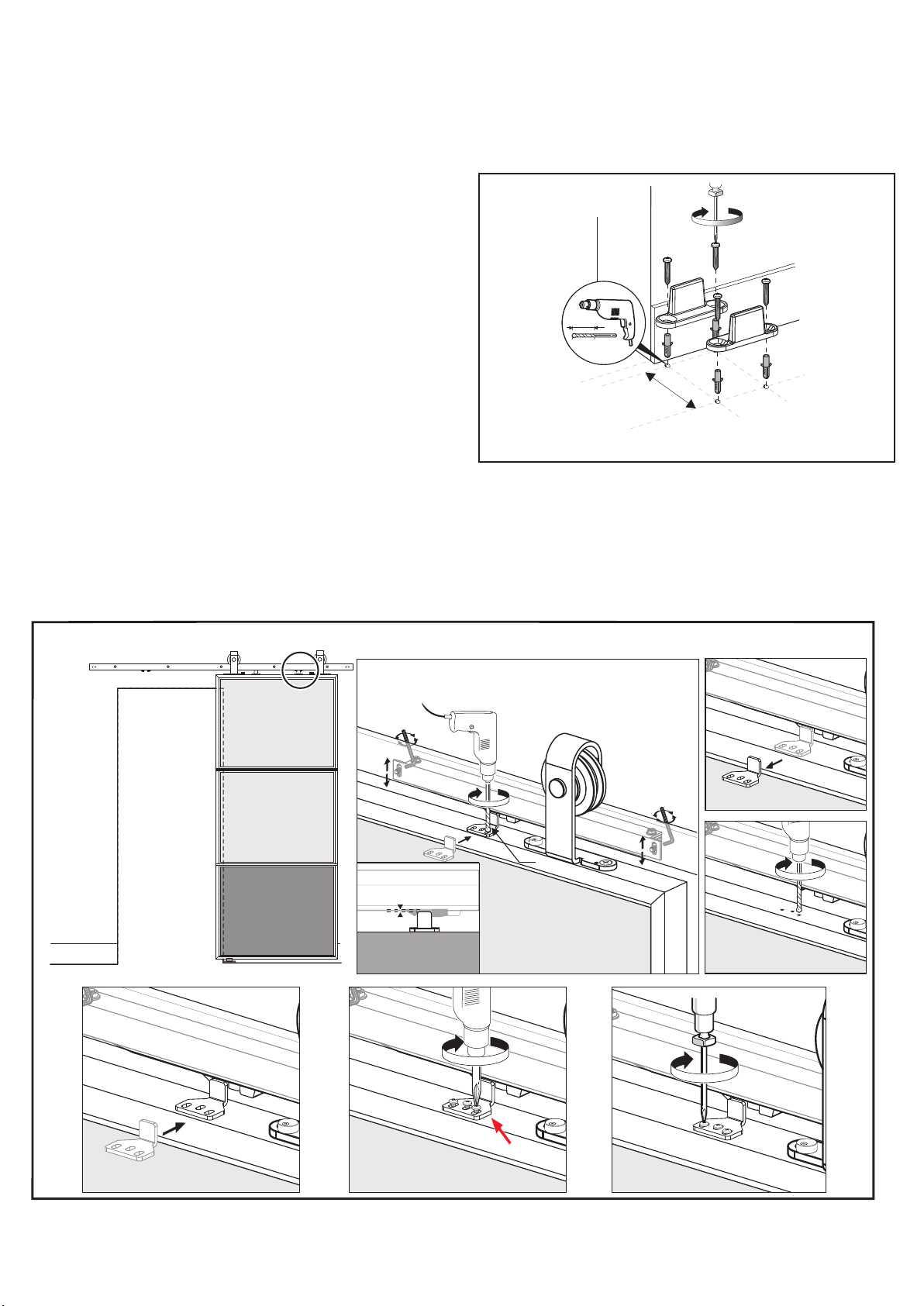
Step 9. Floor-Mounted Door Guide
1/64 ~'' 1/32''
Ø3
0.3~0.5mm
D
o not t
ight
en, re
serv
e clea
rance.
Installation
Once the door is plumb, position the floor-mounted door
guide inside the mortised door, line up close to the opening.
Slide the door side-to-side to ensure functionality for final
placement then mark holes with a pencil and pre-drill 5/16"
holes. If drilling directly into a concrete floor, use the
provided anchors.
Step 10.Install right left close attachment
BARN DOOR HARDWARE KIT
TSQ14BK-6FT+TKM06
INSTALLATION GUIDE
30mm
1 3/16''(30mm)
5/16''(Ø8)
Ø8
1 15/32''(37.5mm)
7mm
Completely open the door,place the actuato r beneath the midd le posit ion of the s lider,e nsure to l eave a gap o f
1/64''~ 1/32''
above the t op of actu ator. Mar k holes on d oor top, insert t he screw s provid ed and sec ure the
actuato r with a phi llips sc rewdri ver.
1
2
3
4
5
6
Page 7
BARN DOOR HARDWARE KIT
0.3~0.5mm
Ø3
1/64 ~'' 1/32''
D
o n
ot tigh
t
e
n
, r
e
s
er
v
e c
lear
a
n
ce
.
TSQ14BK-6FT+TKM06
INSTALLATION GUIDE
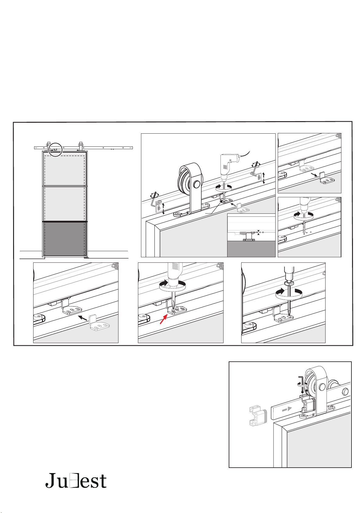
Step 11.Install right soft close attachment
Completely open the door,place the actuato r beneath the midd le posit ion of the s lider,e nsure to l eave a gap o f
1/64''~ 1/32'' a bove the t op of actu ator. Mar k holes on d oor top, insert t he screw s provid ed and sec ure the
actuato r with a phi llips sc rewdri ver.
1
2
3
4
5
6
Step 12. Stopper Installation
Slide the door closed and to correct position of both
stoppers. Using the provided Allen key, tighten into position
to complete the installation of the Barn Door Kit.
X2
Website: www.Ju-Best.com
Feel Free to Contact Us: [email protected]
 Loading...