


FCC Statement
FCC INFORMATION
The equipment has been tested and found to comply with the limits for a Class B
Digital Device, pursuant to part 15 of the FCC Rules. These limits are designed to provide
reasonable protection against harmful interference in a residential installation. This
equipment generates, uses and can radiate radio frequency energy and, if not installed and
used in accordance with the instruction, may cause harmful interference to radio
communication. However, there is no grantee that interference will not occur in a particular
installation. If this equipment dose cause harmful interference to radio or television
reception, which can be determined by turning the equipment off and on , the user is
encouraged to try to correct the interference by one or more of the following measures:
--Reorient or relocate the receiving antenna.
--Increase the separation between the equipment and receiver.
--Connect the equipment into an outlet on a circuit different from that to which the receiver
is connected.
--Consult the dealer or an experienced radio/TV technician for help.
Notice:
The changes or modifications not expressly approved by the party responsible for compliance
could void the user’s authority to operate the equipment.
This device complies with part 15 of the FCC Rules. Operation is subject to the following two
conditions: (1) This device may not cause harmful interference, and (2) this device must
accept any interference received, including interference that may cause undesired operation.
IMPORTANT NOTE:
To comply with the FCC RF exposure compliance requirements, no change to the antenna or
the device is permitted. Any change to the antenna or the device could result in the device
exceeding the RF exposure requirements and void user’s authority to operate the device.

UF-20R / UF-20S / JSS-20 / UF-20TB
Professional Wideband (75MHz)
True Diversity System
59508-072-02
PROFESSIONAL CO., LTD
No.148, 9th Industry Road, Ta-Li Industrial
Park, Taichung City 41280, Taiwan (R.O.C.)
Tel: 886-4-24938803 Fax: 886-4-24914890
Email: jts@jts.com.tw
www.jts.com.tw
UF-20R / UF-20S /
JSS-20 / UF-20TB
Product manual

Product Model
Customer
name
Address
Purchase date
One year product warranty
Equipment
serial number
Contact
number
INDEX
1. System operation instructions
2. Features
2-1 Receiver// UF-20R/UF-20S
............................................................................................. 1
............................................................... 1
....................................... 1
Selling store
stamp
1. Be sure to put the warranty label indicating purchase date on the boom of equipment to ensure your
interest in maintenance and service.
2. Product warranty, starting on the purchase date indicated on “warranty label”, will last for one year; if
the equipment does not have “warranty label”, the warranty period is 15 months from the manufacturing date. If a microphone is broken but not sent back with the equipment, the warranty period is
15 months from the manufacturing date of the microphone.
3. Within the warranty period, if the equipment is broken under normal use as instructed in manual,
please contact the original selling store for repair.
4. When the product is returned for repair, to facilitate proper determination of cause of malfunction
and of whether repair fee is needed, please ship back the equipment and microphone together.
5. Within the warranty period, our company provides repair service at no cost except for the following
conditions that parts and repair may be charged:
a.Damages due to natural disaster or irresistible outside forces.
b.Damages due to drop, water, moisture, corrosion, foreign objects, missing components.
c.e warranty does not cover consumable parts. (such as microphone capsule, ball grille etc.)
d.ose without “warranty label” on equipment or with “warranty label” being damaged and failing to
identify warranty period.
6. Please keep the warranty properly. No replacement will be made if the warranty is missing.
Be sure to put store stamp and ll in purchase date for the warranty to be
effective!
Warranty description
2-2 Handheld Transmitter // JSS-20
2-3 Body-Pack Transmitter // UF-20TB
3. Specication
3-1 Receiver// UF-20R/UF-20S
3-2 Handheld Transmitter // JSS-20
3-3 Body-Pack Transmitter // UF-20TB
3-4 Charger For JSS-20 & UF-20TB & PS-20
3-5 Optional Condenser Microphone
................................................................................. 3
....................................................... 2
................................................... 2
............................................................... 3
....................................................... 5
................................................... 5
........................................ 6
..................................................... 6
4. Parts Identication & Accessories
4-1 Receiver // UF-20R/UF-20S
4-2 Handheld Transmitter // JSS-20
4-3 Body-Pack Transmitter // UF-20TB
4-4 Optional 2-Slot Charger / 8-Slot Charger // CH-2/CH-8
4-5 Optional Condenser Microphone
4-6 Accessories
.................................................................................... 24
5. Connection method
6. Operation
6-1 Receiver// UF-20R/UF-20S
6-2 Handheld Transmitter // JSS-20
6-3 Body-Pack Transmitter // UF-20TB
6-4 Installation of Condenser Microphones
7. Product notes
..................................................................................... 29
............................................................................. 55
8. Important Notice
.............................................................. 9
...................................................... 15
................................................. 17
..................................................... 20
............................................................. 26
............................................................. 29
..................................................... 41
................................................ 47
......................................... 53
................................................................... 56
.......................... 9
.................. 19

1. System operation instructions
• Before connecting to power, make sure the voltage marked on equipment is the same as that
on the power socket.
• Do not place the equipment in damp and hot environment.
• Prior to operation, please dry your hands.
• Keep the equipment away from re and heat source.
• Transmier and receiver need to be adjusted to the same “default channel” or “frequency”.
2. Features
2-1 UHF PLL Wideband True Diversity Receiver // UF-20R/UF-20S
• UHF true diversity technology renders 200-480 meters of operation distance
• Maximum 2400 to 3000 selectable frequencies across 60 to 75 MHz
• Preset 15 groups each of up to 63 compatible channels
• User programmable 6 groups each of 64 channels
• Free space scan function
• JTS Patented obstacle-free RF function synchronizes a transmier by pushing
a buon
• JTS LCX circuit design technology minimizes Companding noise
NEWEST FEATURE:
REMOSET
• e now sends not only the frequency data but also transmier’s RF power,
sensitivity, low cut, key lock and user’s name.
• RF “NO SIGNAL” alert function.
• AF “MUTE” alert function.
• Transmier “LOW BAERY” alert function.
• Built in equalizer
• Power / Antenna cascading output provided. (UF-20R Only)
REMOSET
2-2 UHF PLL Handheld Transmitter // JSS-20
• 2400 to 3000 selectable frequencies
• Preset 15 groups each of up to 63 compatible channels
• Phase-Locked Loop (PLL) synthesized tune
• Extended dynamic range and smooth frequency response.
• Adjustable transmission power between Low and High
• e panel Lock-On function prevents tampering and RF interruption
NEWEST FEATURE:
• Low cut function.
• JTS newest development SAM-8WLN capsule assures outstanding acoustic performance
while minimizes touching noise.
• Interchangeable capsule design for various choices including some classic capsule modules.
• It is designed with slot-in charging feature with two A A NiMH rechargeable baeries.
2-3 UHF PLL Body-Pack Transmitter // UF-20TB
• 2400 to 3000 selectable frequencies
• Preset 15 groups each of up to 63 compatible channels
• Phase-Locked Loop (PLL) synthesized tune
• Extended dynamic range and smooth frequency response.
• Adjustable transmission power between Low and High
• e panel Lock-On function prevents tampering and RF interruption
• Together with JTS various music instrument mics, headset mics and tie clip mics this bodypack
is versatile for all applications.
NEWEST FEATURE:
• It is designed with slot-in charging feature with two A A NiMH rechargeable baeries.
1
Professional Wideband True Diversity System (75MHz)
2

3. Specication
3-1-1. Dual Channel Wideband True Diversity Receiver // UF-20R
Frequency Preparation...............
Frequency Seing..........................
Carrier Frequency Range.........
Channel................................................
Bandwidth..........................................
S/N Ratio............................................
T.H.D. ....................................................
Chassis...................................................
Preset Channels / Group.........
Display...................................................
Display Contents...........................
Sensitivity.............................................
Receiving Mode..............................
Audio Output Level.....................
XLR AF Output Impedance
Frequency Response...................
Squelch..................................................
Power Supply.....................................
Output Connector........................
Dimension(mm)...........................
PLL Synthesized Control
JTS patented obstacles-free RF REMOSET
UHF 470~960MHz
Dual
60~75MHz Wideband
>108dB(A)
<0.5%@1KHz
1U standard metal chassis
*From group 1 ~ 15 up to 63 interference-free compatible channels.
*844 preset channels/group and 3000 selectable frequencies across
60 to 75 Hz Bandwidth.
*User programmable from U1 ~ U6 each of 64 channels reserved.
LCD and LED
Group, Channel, Frequency, Antenna A/B ,RF/AF Level Meter,
Mute Display, Transmier Baery Status, REMOSET ID Number,
User Name, Squelch
6dBμV, at S/N>80dB
True diversity
Maximum 6dBu
150/600Ω (mic/Line)
50Hz~18kHz, with high-pass lter
Pilot Tone & Noise Mute
100~240V or 12V DC
2 XLR Balanced Socket /
2 Ø6.3mm Balanced phone jack
480mm(W)x45Mmm(H)x260mm(D)
3-1-2. Single Channel Wideband True Diversity Receiver // UF-20S
Frequency Preparation...............
Frequency Seing..........................
Carrier Frequency Range.........
Channel................................................
Bandwidth..........................................
S/N Ratio............................................
T.H.D. ....................................................
Chassis...................................................
Preset Channels / Group.........
Display...................................................
Display Contents...........................
Sensitivity.............................................
Receiving Mode..............................
Audio Output Level.....................
XLR AF Output Impedance
Frequency Response...................
Squelch..................................................
Power Supply.....................................
Output Connector........................
Dimension(mm)...........................
PLL Synthesized Control
JTS patented obstacles-free RF REMOSET
UHF 470~960MHz
Single
60~75MHz Wideband
>108dB(A)
<0.5%@1KHz
1/2U standard metal chassis
*From group 1 ~ 15 up to 63 interference-free compatible channels.
*844 preset channels/group and 3000 selectable frequencies across
60 to 75 Hz Bandwidth.
*User programmable from U1 ~ U6 each of 64 channels reserved.
LCD and LED
Group, Channel, Frequency, Antenna A/B ,RF/AF Level Meter,
Mute Display, Transmier Baery Status, REMOSET ID Number,
User Name, Squelch
6dBμV, at S/N>80dB
True diversity
Maximum 6dBu
150/600Ω (mic/Line)
50Hz~18kHz, with high-pass lter
Pilot Tone & Noise Mute
100~240V or 12V DC
1 XLR Balanced Socket /
1 Ø6.3mm Balanced phone jack
212mm(W)x44Mmm(H)x 213.9mm(D)
3
Professional Wideband True Diversity System (75MHz)
4

3-2 Professional Wideband Handheld Transmitter // JSS-20
3-4 Optional Charger For JSS-20 & UF-20TB & PS-20
Frequency Preparation...............
Carrier Frequency Range.........
Bandwidth..........................................
RF Outputs........................................
Stability..................................................
Frequency Deviation...................
LCD Display......................................
PLL Synthesized Control
UHF 470~960 MHz
60~75MHz Wideband
Low / High
<±10KHz
±48KHz (Peak)
Group, Channel, Frequency, Battery Status, User Name,
GAIN Adjust
Controls................................................
Power ON/OFF, AF Level, Frequency (Up/Down), Lock-on
Mode, REMOSET ID, RF Output Adjust
Spurious Emissions......................
Audio Frequency Response....
Capsule Module.............................
Baery....................................................
Dimension(mm)............................
Weight....................................................
<-50 dBC
50Hz~18k Hz
Interchangeable
AA NiMH x2
50mm(W)x253mm(H)x35.5mm(D)
350g
3-3 UHF PLL Body-Pack Transmitter // UF-20TB
Frequency Preparation...............
Carrier Frequency Range.........
Bandwidth..........................................
RF Outputs........................................
Stability..................................................
Frequency Deviation...................
Chassis...................................................
LCD Display.....................................
PLL Synthesized Control
UHF 470~960 MHz
60~75MHz Wideband
Low / High
<±10KHz
±48KHz (Peak)
Aluminium alloy
Group, Channel, Frequency, Battery Status, User Name ,
GAIN Adjust
Controls................................................
Power ON/OFF, AF Level, Frequency (Up/Down), Lock-on
Mode, REMOSET ID, RF Output Adjust
Output Connector........................
Spurious Emissions.......................
Audio Frequency Response....
Baery.....................................................
Dimension(mm)............................
Weight....................................................
4P Mini XLR
<-50 dBC
50Hz~18k Hz
AA NiMH x2
62mm(W)x80.3mm(H)x22.6mm(D)
93g
Model No...............................
Input...........................................
Output......................................
Model No...............................
Input...........................................
Output......................................
CH-2 ( 2-Slot Charger )
AC 100~240V, 0.4A max
DC 12V, 1A
CH-8 ( 8-Slot Charger )
AC 100~240V, 1.2A max
DC 15V, 3A
3-5 Optional Condenser Microphone
Lavaliere Microphone
Model No...............................
Connector..............................
Frequency Response......
Polar Paern..........................
Sensitivity (at 1000Hz)
Impedance.............................
Max. SPL for 1% THD
Dimension(mm)..............
CM-501
4P Mini XLR
100~15,000 Hz
Cardioid
-60±3 dB
2.2kΩ
130dB
Ø10.1mm(W)
* 26.4mm(H)
Net Weight............................
21.5g
CM-201i
4P Mini XLR
60~15,000 Hz
Omni-directional
-60±3 dB
2.2kΩ
130dB
Ø5mm(W)
* 9mm(H)
20.7g
CM-125i
4P Mini XLR
50~18,000 Hz
Omni-directional
-53±3 dB
4.4kΩ
130dB
Ø4mm(W)
* 11mm(H)
7g (cable excluded)
5
Professional Wideband True Diversity System (75MHz)
6

Headset Microphone
Ear-hook Microphone
Model No...............................
Connector...............................
Frequency Response......
Polar Paern..........................
Sensitivity (at 1000Hz)
Impedance.............................
Max. SPL for 1% THD
Dimension(mm)..............
Net Weight............................
Model No...............................
Connector...............................
Frequency Response......
Polar Paern..........................
Sensitivity (at 1000Hz)
Impedance.............................
Max. SPL for 1% THD
Dimension(mm)..............
Net Weight............................
CM-214i
801C4
(4P Mini XLR)
60~15,000 Hz
Omni-directional
-60±3 dB
1.8kΩ
130dB
125mm(W)
* 134mm(H)
* 157mm(D)
32.9g
CM-235i
801C4
(4P Mini XLR)
50~18,000 Hz
Omni-directional
-53±3 dB
1.8kΩ
130dB
155mm(W)
* 134mm(H)
* 157mm(D)
17g (cable excluded)
CM-214Ui
801C4
(4P Mini XLR)
30~18,000 Hz
Cardioid
-68±3 dB
680Ω
130dB
205mm(W)
* 134mm(H)
* 157mm(D)
38.4g
CX-504
4P Mini XLR
30~18,000 Hz
Cardioid
-68±3 dB
680Ω
130dB
285mm(W)
* 55mm(H)
* 111.3mm(D)
56.3g
CM-214ULi
801C4
(4P Mini XLR)
100 ~ 18,000Hz
Cardioid
-65±3 dB
1.8kΩ
120dB
125mm(W)
* 134mm(H)
* 157mm(D)
18g (cable excluded)
Model No...............................
Connector..............................
Frequency Response......
Polar Paern..........................
Sensitivity (at 1000Hz)
Impedance.............................
Max. SPL for 1% THD
CM-801/CM-804i
801C4 (4P Mini XLR)
60~15,000 Hz
Omni-directional
-64±3 dB
1.8kΩ
130dB
Compatible Instrument Microphone
Model No...............................
Connector..............................
Frequency Response......
Polar Paern..........................
Sensitivity (at 1000Hz)
Impedance.............................
Max. SPL for 1% THD
Good For.................................
Model No...............................
Connector..............................
Frequency Response......
Polar Paern..........................
Sensitivity (at 1000Hz)
Impedance.............................
Max. SPL for 1% THD
Good For.................................
CX-500
4P Mini XLR
20~20,000 Hz
Omni-directional
-58±3dB
1.5kΩ
130 dB
Violin
CX-508W
4P Mini XLR
50~18,000 Hz
Cardioid
-67±3 dB
220Ω
130 dB
Winds
CM-8015/CM-825i
801C4 (4P Mini XLR)
50~18,000 Hz
Omni-directional
-53±3 dB
1.8kΩ
130dB
CX-500F
4P Mini XLR
20~20,000 Hz
Omni-directional
-58±3dB
1.5kΩ
130 dB
Flutes
CX-516W
4P Mini XLR
30~18,000 Hz
Cardioid
-67±3 dB
220Ω
130 dB
Accordion
CX-520
4P Mini XLR
50~16,500 Hz
Supercardioid
-78±3dB
600Ω
148 dB
Harmonica
7
Professional Wideband True Diversity System (75MHz)
8
4. Parts Identication & Accessories
4-1 Buttons and LCD Displays of Wideband True Diversity Receiver//
UF-20R/UF-20S
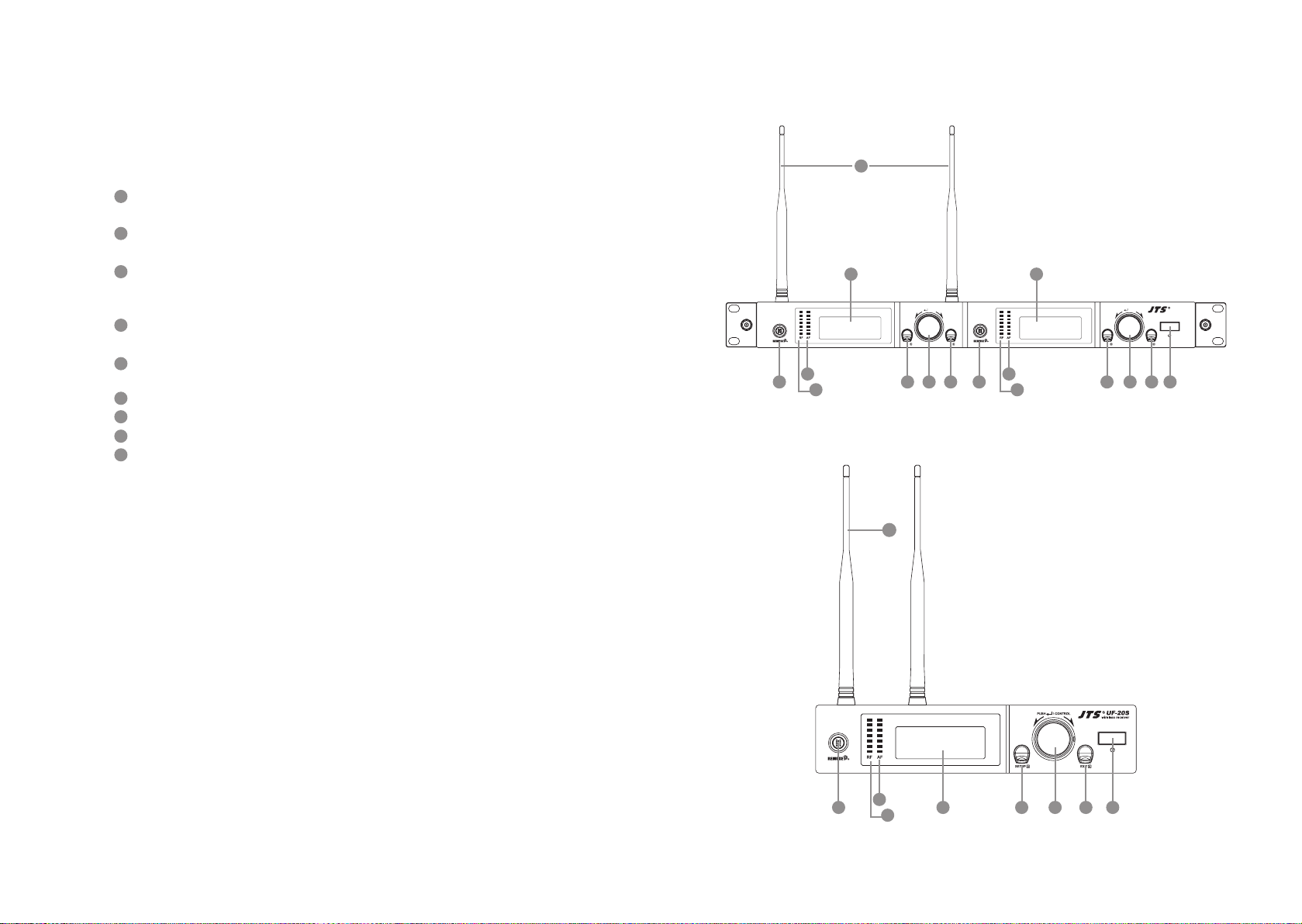
(1) Front panel
1
Power : Power on: Push the Power buon to turn on
Power o: Push and hold the Power buon until “Power O” shows on the LCD
2
EXIT key: Push EXIT to cancel the selection and exit the menu when the UF-20R is in
the “Seing Menu.”
3
Rotary switch: When in the “Function Seing Menu,” the rotary switch allows the selection of the desired functions up and down; push the rotary switch (or the SETUP) to enter
the selection, rotate the switch to select the desired seing and push SETUP to save it.
4
SETUP: Push and hold for 2 seconds to enter the “Seing Menu;” when the selection and
seing is done with [3. Rotary Switch], push SETUP to save the seing.
5
REMOSET: When the seing is done on the receiver, push REMOSET to transmit the
seings to the handheld or body-pack transmier.
6
LCD display: See [4-1-2. Description of receiver LCD display].
7
AF indication: shows the strength of current audio signal.
8
RF indication: shows the strength of current radio signal.
9
Antenna
9
6 6
PUSH / CONTROL
EXITSETUP
7 7
5 5
8 8
3 34 42 2 1
9
PUSH / CONTROL
EXITSETUP
UF-20R
UF-20R
wireless receiver
9
Professional Wideband True Diversity System (75MHz)
UF-20S
7
5
8
3 2 146
10
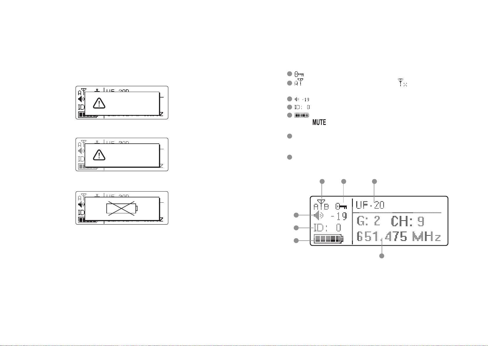
4-1-2. Description of receiver LCD display
Display color:
Red: (1) No RF signal is received from any transmier, and the LCD shows:
No Signal
(2) Transmier on mute.
Mic Mute
(3) Transmier baery low.
Orange: RF and AF signals are received from transmiers.
10
11
: Panel Lock On activated on receiver.
: It indicates antenna A or B is receiving signal; is shown when no signal is
received from a microphone.
12
13
14
: receiver volume.
: device ID: from 0 to 255.
: transmier baery level
is shown when no signal is received from transmier or the transmier
is mute.
15
G: the current group in use; from 1 to 15
CH: the current channel in use, up to 63
Frequency: the current frequency in use
16
User’s Name (dened in the username seing in the menu)
10 1611
12
13
14
11
Professional Wideband True Diversity System (75MHz)
15
12
4-1-3. Back panel // UF-20R
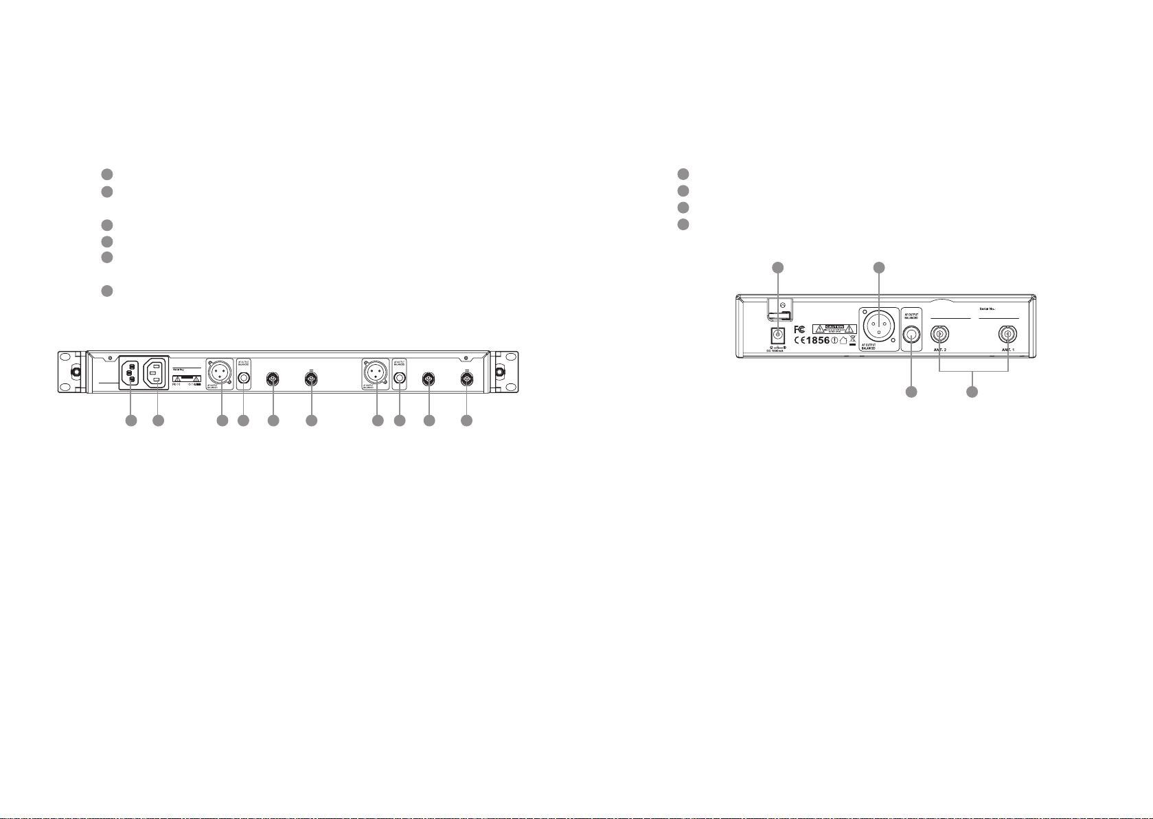
4-1-4. Back panel // UF-20S
17
POWER: AC power, 100 ~ 240VAC
18
AC power outlet(for cascading): it allows power connection to next receiver with an
extension AC power cable.
19
AF OUTPUT BALANCED: XLR balanced audio output jack
20
AF OUTPUT BALANCED: Ø6.3mm balanced audio output jack
21
Antenna A (or B) In: antenna input (or antenna booster jack + 12VDC/150mA); it con-
nects to antenna or antenna booster through a BNC signal cable.
22
RF A (or B) Out: RF signal output socket(for cascading): Provide RF signal to next
receiver.
POWER
100V~240VAC~
50/60Hz, 2A
Freq.Range:
CAUTION
RISK OF ELECTRIC SHOCK
DO NOT OPEN
1856
Made in Taiwan
RF B Out
Antenna B In
12V out
191917 18 2020 2222 2121
RF A Out
Antenna A In
12V out
23
Power receptacle: connect to power supply (DC12V/1000mA)
24
Balanced XLR MIC output
25
Ø 6.3mm balanced output
26
BNC antenna socket: ANT 1 and ANT 2, set antennas vertical or sloping for beer
reception.
23 24
Freq.Range:
Made in Taiwan
12V
25 26
13
Professional Wideband True Diversity System (75MHz)
14

4-2 Buttons and LCD Displays of UHF PLL Handheld Transmitter //
JSS-20
4-2-1. Panel functions
27
LCD display
28
SET: set and save handheld transmier
、 : up and down buons to select the desired function of the handheld device.
29
30
Power
(1) Handheld transmier on
Power on: push the Power buon.
Power o: push and hold the power buon for one second till the display shows
“Power O.”
(2) Mute: the handheld transmier is in use (with main screen on display)
To mute: Short push the power buon display “to activate mute.”
To cancel: Short push the power buon display again “to deactivate mute.”
(3) Exit Seing Menu:
Already in the Seing Menu: push the power buon to return to main screen.
Already in a function seing: push the power buon to return to the Seing Menu
and again to return to the main screen.
31
Baery tray
32
Recharging jack: for power charging.(Charger is optional)
33
Slide cover
34
Ball grille
35
LED status display
Green: power on
Blue: Remoset transmiing (approximately 5 seconds)
Red: baery low
Flashing red: mute
Flashing red/green: baery low and mute
27
28
33
29
32
30
4-2-2. Description of LCD display
36
Device ID: from 0 to 255
37
Sensitivity: -15dB ~ +15dB
38
Low Cut indication
39
Transmission Power: Hi (High) and Lo (Low)
40
User name
41
Baery level: in 5 levels
G: the group in use, from 1 to 15
CH: the channel in use,
up to 63
42
Lock On Statue
43
Frequency: it shows
the RF frequency
41
31
35
28
39 37
Lo
JSS-20
G: 2 C: 10
34
36 38
ID23
40
42
15
Professional Wideband True Diversity System (75MHz)
687.250 MHz
43
16

4-3 Buttons and LCD Displays of UHF PLL Body-Pack Transmitter //
UF-20TB
4-3-1. Panel functions
44
LCD display
45
Baery level
Red: baery low; replace baery
46
REMOSET indicators
Blue: Remoset transmiing (approximately 5 seconds)
47
Power:
(1)On: push the power buon
O: push and hold the power buon for 2 seconds till the display shows “Power
O.”
(2)Exit Seing Menu: when in the Seing Menu, push the power buon to return to
the main screen.
、 : up and down buons for selection
48
49
SET: to set and save
50
Mute: switch to “MUTE” to mute the transmier and the red indicator starts to ash.
51
Baery tray
50
4-3-2. Description of LCD display
52
Transmission Power: Hi (High) and Lo (Low)
53
User Name
54
Indicate current Group and current Channel
55
Frequency: it shows the RF frequency
56
Baery level: in 5 levels
57
Sensitivity Value
58
Low Cut indication
59
Aenuate Indication
60
Lock On Statue
52
53
55
56
57
58 59
AT
Hi
UF-20TB
G: 1 C: 11
633.875 MHz
IDoff
-12dB
For screen display and operation please refer to “6-3. System operation setup for
Body-Pack transmier”.
60
54
44
45
46
47
17
Professional Wideband True Diversity System (75MHz)
AT
Hi
UF-20TB
G: 1 C: 11
633.875 MHz
IDoff
-12dB
UHF PLL Transmitter
Hi
UF-20TB
G: 1 C: 11
633.875 MHz
AT
IDoff
-12dB
48
49
51
18

4-4 Optional 2-Slot Charger / 8-Slot Charger // CH-2/CH-8
61
LED Indicator
Full Charged / Standby:Green
Charging:Flash Green
Fault:Flash Red
*Charging Time:3 hours
61
61
CH-2 CH-8
4-5 Optional Condenser Microphone
Lavaliere Microphone // CM-501 / CM-201i / CM-125i
62
Clip
63
4 Pin Mini XLR
64
Windscreen
62
62 62
63
64
64
CM-501 CM-201i CM-125i
3
.
3
CAUTIO
R
I
S
K
O
F
E
L
E
D
C
O
T
N
R
N
I
O
C
T
S
O
H
P
O
E
C
N
K
64
19
Professional Wideband True Diversity System (75MHz)
20

Headset Microphone // CM-214i / CM-214Ui / CM-214ULi / CM-235i /
CX-504
65
Gooseneck
66
Adjustable headband
67
Headband
68
4 Pin Mini XLR
69
Windscreen
66
66
66
Ear-hook Microphone // CM-801 / CM-804i / CM-8015 / CM-825i
70
Boom
71
Adjustable Headband
72
Adjustable ear hook
73
Detchable Cable
74
Cable Clip
75
Windscreen
76
4 Pin Mini XLR
75
70
73
CM-801
74
72
72
CM-214i CM-214Ui
69
68
65
69
66
CM-235i CX-504
69
CM-214ULi
Standard :
4 Pin Mini XLR
76
65
65
69
69
67
65
65
75
70
CM-804i
75
70
73
CM-8015
74
75
70
CM-825i
73
71
74
72
72
71
73
74
21
Professional Wideband True Diversity System (75MHz)
22

Compatible Instrument Microphone // CX-500 / CX-500F / CX-520 /
CX-508W / CX-516W
77
Gooseneck
78
Clip
79
Bracket
80
Volume Control
81
Windscreen
82
4 Pin Mini XLR
81
CX-500
82
77
4-6-1. Accessories for UF-20R
83
AC power cable * 1
84
BNC/BNC RF extension cable for cascading * 2
85
Front antenna signal cable
86
Extension AC power cable for series connection * 1
87
XLR(M)/XLR(F) Audio cable * 2
88
MA-935 Capsule adaptor
89
PS-20 rechargeable baery module
90
CH-2 double-slot charger
91
CH-8 8-slot charger
92
Antenna * 2
93
MH-56 Microphones Holder * 2
94
Color ID housing * 7
Option
Option
Option
Option
Option
84
81
CX-500F
78
86 87
SELF-MA N
SM-018
SM-006
SELF-MA N
83
88
85
81 81
89 90
77
77
N
WA
I
TA
IN
E
D
MA
PS-20
91
3
.
3
CAUTIO
R
I
S
K
O
F
E
L
E
D
C
O
T
N
R
N
I
O
C
T
S
O
H
P
O
E
C
N
K
80
92 93
94
CX-520
CX-508W
79
78
CX-516W
23
Professional Wideband True Diversity System (75MHz)
24

5. Connection method
4-6-2. Accessories for UF-20S
95
AC/DC power adapter * 1:
Switching power adapter
AC IN: AC100~240V/50~60Hz
DC OUT: DC12V/1000 mA
96
XLR(M)/XLR(F) Audio cable * 1
97
MA-935 Capsule adaptor
98
PS-20 rechargeable baery module
99
CH-2 double-slot charger
100
CH-8 8-slot charger
101
Antenna * 2
102
MH-56 Microphones Holder * 1
103
Color ID housing * 7
95 96 97
98
N
WA
I
TA
IN
E
D
MA
PS-20
Option
Option
Option
99
5-1-1. Receiver connection method // UF-20R
1. UF-20 output to a mixer or an amplier:
Audio cable: XLR or Ø 6.3mm audio cable, one end connects to audio output of UF-20R “AF
OUTPUT BALANCED”, while the other end connects to audio input of a mixer or an amplier.
2. Connect to power
Option
Connect to AC outlet: one end connects to receiver “power input”, while the other end connects to AC power receptacle.
32
Amplier
100
3
.
3
CAUTIO
R
I
S
K
O
F
E
L
E
D
C
O
T
N
R
N
I
O
C
T
S
O
H
P
O
E
C
N
K
POWER
100V~240VAC~
50/60Hz, 2A
Freq.Range:
Made in Taiwan
CAUTION
RISK OF ELECTRIC SHOCK
DO NOT OPEN
1856
Step 2
Audio output
Antenna B In
12V out
RF B Out
Antenna A In
12V out
RF A Out
101 102
25
Professional Wideband True Diversity System (75MHz)
Step 1
Power supply
AC transformer
103
Power receptacle
Figure 1
26

5-1-2. Receiver connection method // UF-20S
5-2 Cascading of AC power cable and antenna (UF-20R Only)
1. UF-20S output to a mixer or an amplier:
Audio cable: XLR or Ø 6.3mm audio cable, one end connects to audio output of UF-20S “AF
OUTPUT BALANCED”, while the other end connects to audio input of a mixer or an ampli-
er.
2. Connect to power
Connect to AC/DC adapter: one end connects to receiver “DCV INPUT”, while the other
end connects to AC power receptacle.
32
Amplier
Step 1
Audio output
Freq.Range:
Made in Taiwan
12V
Power supply
AC/DC transformer
Step 2
It is allowed to cascade power and antennas for 10 units.
Power socket
Freq.Range:
CAUTION
RISK OF ELECTRIC SHOCK
DO NOT OPEN
1856
Made in Taiwan
Freq.Range:
CAUTION
RISK OF ELECTRIC SHOCK
DO NOT OPEN
1856
Made in Taiwan
More UF-20Rs…
10 units
POWER
100V~240VAC~
50/60Hz, 2A
POWER
100V~240VAC~
50/60Hz, 2A
RF B Out
RF B Out
Antenna B In
12V out
Antenna B In
12V out
RF A Out
RF A Out
Antenna A In
12V out
Antenna A In
12V out
Figure 1
27
Professional Wideband True Diversity System (75MHz)
Power receptacle
POWER
100V~240VAC~
50/60Hz, 2A
POWER
100V~240VAC~
50/60Hz, 2A
Freq.Range:
CAUTION
RISK OF ELECTRIC SHOCK
DO NOT OPEN
1856
Made in Taiwan
Freq.Range:
CAUTION
RISK OF ELECTRIC SHOCK
DO NOT OPEN
1856
Made in Taiwan
RF B Out
RF B Out
Antenna B In
12V out
Antenna B In
12V out
RF A Out
RF A Out
Antenna A In
12V out
Antenna A In
12V out
28

6. Operation
6-1 Operation settings for Wideband True Diversity Receiver //
UF-20R/UF-20S
6-1-1. Turn the receiver power on.
(2) REMOSET successful: the blue indicator on the transmier is on for 3 seconds and that
on the receiver stops ashing.
(1) Install the receiver antenna.
(2) Push the power buon to turn
1
PUSH / CONTROL
UF-20R
wireless receiver
the power on
(3)To turn o: push and hold the power
buon till the display shows
“Power O.”
EXITSETUP
6-1-2. REMOSET function:
(1) Push the REMOSET buon and the blue indicator starts to ash, indicating the receiver
is transmiing data (Figure 1).
*When using the REMOSET function of UF-20R, it is recommended to carry out RE-
MOSET one by one. is is to prevent the interference between the REMOSET signals
and the failure of data transmiing.
Fig. 2
(3)REMOSET failed: Check the following when the blue indicator on the receiver ashes in
a slow pace:
1)If the receiver and the transmier are of the same frequency band.
2)e “Remoset Function” on in the function menu of Transmier is “activated;”
3)e “Device ID” is the same on both the receiver and transmier.
4)e transmier baery is low (synchronization is not possible if it is too low).
Notes:
(1)For receiver seings, please see: “6. Device ID” and “7. Microphone Seing” of 6-1
Operation seings for Wideband True Diversity Receiver.
(2)For handheld transmier seings, please see: “5. Device ID” and “6. Remoset
Function” of 6.2 Operation seings for handheld transmier system.
(3)For body-pack transmier seings, please see: “5. Device ID” and “6. Remoset
Function” of 6.3 Operation seings for body-pack transmier system.
29
Professional Wideband True Diversity System (75MHz)
Figure 1
30

6-1-3. Menu setting
Push and hold the SETUP buon for 2 seconds to enter the menu.
(1) Turn the rotary switch clockwise or counterclockwise to select the desired function.
Push the switch (or the SETUP buon) to enter the seing screen. Push EXIT to
return to the main menu if nothing is done.
(2) In the seing screen, turn the rotary switch to the desired value or function, and push
SETUP to save the seing.
(3) EXIT: return to main menu or main screen; no saving or modication of seings is
made; push EXIT once to return to the menu and again to return to the main screen.
1. Frequency : this is to dene the frequency.
(1) Rotate the rotary switch to “1. Frequency ” Push the
rotary switch (or SETUP) to enter the frequency adjustment screen.
(2) Adjust the le three digits of frequency: rotate the
switch [+/-] in steps of 1MHz. Push the rotary switch
to save the selected value.
(3) Adjust the right three digits of frequency: rotate the
switch [+/-] in steps of 0.025MHz:
Push the rotary switch to save the selected value.
Note: you may select to adjust the le or right part of
frequency by pushing the rotary switch.
2. Group/Channel : this is to dene groups and channels.
(1) Rotate the rotary switch to “2. Group/ Channel.” Push
SETUP (or the rotary switch) to enter the seing screen.
31
Professional Wideband True Diversity System (75MHz)
1. Frequency
M
2.Group/Channel
E
3.User Group
N
4. Scan
U
Setup Frequency
687 .250 MHz
G: 1 CH: 1
Setup Frequency
687 . 250 MHz
G: 1 CH: 1
1. Frequency
M
2.Group/Channel
E
3.User Group
N
4. Scan
U
(2) Rotate the switch to select a group “G:” from 1 to 15.
Push the rotary switch to save the selected value.
(3) Rotate the switch to select a channel “CH:” from up to
63 channels. Push the rotary switch to save the selected
value.
Note: you may select to adjust the group or channel by
pushing the rotary switch.
3. User Group: groups and channels dened by user
Rotate the rotary switch to “3. User Group.” Push the rotary
switch (or SETUP) to enter the seing screen.
#1. Custom Group: the user is to dene a group
(1) Rotate the rotary switch to “1. Custom Group.” Push the
rotary switch to enter the seing screen.
(2) For “every push” of the rotary switch, the display jumps
from group (G), channel (CH) to frequency (the le
or right three digits): when the frequency shows “---.--MHz,” it means that this channel (G/CH) is not in use.
(3) Rotate the rotary switch to select the group, channel or
frequency for seing; push SETUP to save the seing.
Setup Group
G: 2 CH: 10
633.625MHz
Setup Group
G: 2 CH: 10
633.625MHz
1. Frequency
M
2.Group/Channel
E
3.User Group
N
4. Scan
U
1. Custom Group
2. Clear Group
3. Return
Setup User Group
G: U1 CH: 1
- - -.- - - MHz
Setup User Group
G: U1 CH: 1
- - -.- - - MHz
Setup User Group
G: U1 CH: 1
624.000 MHz
Setup User Group
G: U1 CH: 1
624.025 MHz
32

#2. Clear Group: delete a group dened by us er
(1) Rotate the rotary switch to “2. Clear Group.” Push the
rotary switch to enter the “Clear Group” screen.
(2) Rotate the rotary switch to select the group to be deleted
and push the rotary switch.
Select “Conrm” and all the channels and frequencies of
that group is returned to “---.---MHz.” Select conrm or
cancel and push the rotary switch.
#3. Return: return to main menu
Rotate the rotary switch to “3. Return,” and push the switch to
return to the main menu.
4. Scan: scan for channels
(1) Rotate the rotary switch to “4. Scan.” Push the rotary switch
(or SETUP) to enter the channel scanning screen.
#1. All Groups: scan all groups
(1) Rotate the rotary switch to “1. All Groups.” Push the rotary
switch (or SETUP) to enter the menu.
(2) Enter the “All Groups” (push EXIT to go back up a level)
and push the rotary switch to scan.
(3) e progress in % is shown on the screen during the scan-
ning. To stop scanning, just push EXIT.
(4) e display goes to the “2. Result List” screen automatically
aer the scanning is completed. User may select the list in
the menu.
e user may view the scan result in the screen. Rotate the
rotary switch to select an available channel. Push SETUP
to save seings.
1. Custom Group
2. Clear Group
3. Return
Group: U1
Rotary to select
Push “Entrer” to clear
Push “Exit” to return
Group “U1” will be cleared
continues?
Yes NO
1. Custom Group
2. Clear Group
3. Return
1. Frequency
M
2.Group/Channel
E
3.User Group
N
4. Scan
U
1. All Groups
2. Result List
3. Current Group
4. Return
Scan All Groups
Press Setup or Enter to
start scan.
Press Exit to quit.
Scan All Groups
Scanning... 2%
#2. Result List: view the scan result list
Rotate the rotary switch to “2. Result List.” Push the rotary
switch and enter the menu screen to view the result. Select an
available channel and push SETUP to save the seings.
#3. Current Group: scan a single group
(1) Rotate the rotary switch to “3. Current Group.” Push the
rotary switch to enter the menu screen.
(2) Push the rotary switch to start scanning a single group.
(3) e display shows OK aer scanning; for “every push” of
the rotary switch, the unit starts to scan the next group.
Select and push SETUP to save the seing. Push EXIT to
go back to the previous level.
#4. Return: return to main menu
Rotate the rotary switch to “4. Return.” Push the rotary switch
to return to the main menu.
5. Squelch: adjust the receiver sensitivity
(1) Rotate the rotary switch to “5. Squelch.” Push the rotary
switch (or SETUP) to enter the adjustment menu.
(2) Rotate the rotary switch to adjust the sensitivity. 0dB is the
standard value. Push SETUP to save the seing. e higher
the value, the lower the receiver sensitivity, and the lower
the value, the higher the receiver sensitivity.
1. All Groups
2. Result List
3. Current Group
4. Return
Scan Result List
G: 1 CH: 1
Open Channel : 48
1. All Groups
2. Result List
3. Current Group
4. Return
Scan Current Group
G: 1 CH:1
Scan Current Group
G: 1 CH: 1 OK
Press Setup to Save.
1. All Groups
2. Result List
3. Current Group
4. Return
5. Squelch
M
6. Device ID
E
7. Mic Config
N
8. Volume
U
Setup Squelch
0
33
Professional Wideband True Diversity System (75MHz)
34

6. Device ID: dene the ID code of device
(1) Rotate the rotary switch to “6. Device ID.” Push the rotary
switch (or SETUP) to enter the ID seing menu.
(2) Rotate the rotary switch to select the ID from 0-255; push
SETUP to save the seing.
is seing determines the use of REMOSET. e receiver
and transmier must have the same “device ID” in order to use
REMOSET.
Note: this is not a problem if the microphone ID is not
activated.
5. Squelch
M
6. Device ID
E
7. Mic Config
N
8. Volume
U
Setup Device ID
23 〔0~255〕
(3. LowCut: base aenuation
Rotate the rotary switch to “3. LowCut.” Push the rotary
switch (or SETUP) to enter the adjustment menu.
e Low Cut is not set.
Rotate the rotary switch one notch clockwise to select
Low Cut (as shown on the right). Push SETUP to save the
seing.
1. Sensitivity
2. Attenuate
3. Low Cut
4. RF Power
Mic Low Cut
Mic Low Cut
7. Mic Cong: Adjust the REMOSET seing of transmier.
(1) Rotate the rotary switch to “7. Mic Cong.” Push the rotary
switch (or SETUP) to enter the adjustment menu.
(2) Rotate the rotary switch to select the desired item.
(1. Sensitivity
(1) Rotate the rotary switch to “1. Sensitivity.” Push the rotary
switch (or SETUP) to enter the adjustment menu.
Rotate the rotary switch to select and set the value. Push
SETUP to save the seing; range: -15dB - +15dB
(2. Aenuate: it sets the aenuation of microphone input
volume from body-pack transmier.
Rotate the rotary switch to “2. Aenuate.” Push the rotary
switch (or SETUP) to enter the adjustment menu.
Rotate the rotary switch to activate or deactivate.
Push SETUP to save the seing.
Note: this is not supported by handheld transmiers.
5. Squelch
M
6. Device ID
E
7. Mic Config
N
8. Volume
U
1. Sensitivity
2. Attenuate
3. Low Cut
4. RF Power
Mic Sensitivity
1. Sensitivity
2. Attenuate
3. Low Cut
4. RF Power
Mic Attenuate
ON
OFF
Mic Attenuate
ON
0 dB
(4. RF Power: RF frequency
Rotate the rotary switch to “4. RF Power” Push the rotary
switch (or SETUP) to enter the adjustment menu.
Rotate the rotary switch to select RF Power.
High → high RF Power
Low → low RF Power
Push SETUP to save the seing.
(5. KeyLock
Rotate the rotary switch to “5. KeyLock.” Push the rotary
switch (or SETUP) to enter the adjustment menu.
Rotate the rotary switch to select lock or unlock.
Push SETUP to save the seing.
(6. Remoset Cong: to select or unselect REMOSET seings.
(1) Rotate the rotary switch to “6. Remoset Cong.” Push the
rotary switch (or SETUP) to enter the seing menu.
1. Sensitivity
2. Attenuate
3. Low Cut
4. RF Power
Mic RF Power
High
Low
4. RF Power
5. Kry Lock
6. Remoset Config
7. Return
Mic KeyLock
Lock ON
Lock OFF
4. RF Power
5. Kry Lock
6. Remoset Config
7. Return
35
Professional Wideband True Diversity System (75MHz)
OFF
36

(2) Rotate the rotary switch to select and push the switch to
check the selection; REMOSET only synchronizes on
checked selections.
9. Equalizer: equalizer seings
(1) Rotate the rotary switch to “9. Equalizer.” Push the rotary
switch (or SETUP) to enter the seing menu.
9. Equalizer
M
a. Output Level
E
b. Antenna Power
N
c. User Name
U
□ Frequency
□ Sensitivity
□ Aenuate
□ Low Cut
□ RF Power
□ Key lock
□ UserName
□ Save and Exit
□ Exit Without Save
Select and push SETUP to save the seings.
*At least one item must be selected.
(7. Return: to main menu
Rotate the rotary switch to “7. Return” and push the switch
to return to main menu.
8. Volume: volume adjustment
(1) Rotate the rotary switch to “8. Volume.” Push the rotary
switch (or SETUP) to enter the volume adjustment menu.
(2) Rotate the rotary switch to locate the desired volume from
Mute, -50dB to 0dB. Push SETUP to save the seing.
4. RF Power
5. Kry Lock
6. Remoset Config
7. Return
5. Squelch
M
6. Device ID
E
7. Mic Config
N
8. Volume
U
Setup Volume
-10dB
9. Equalizer
M
a. Output Level
E
b. Antenna Power
N
c. User Name
U
(2) Rotate the rotary switch to select one of the following:
Equalizer deactivated
Decrease low frequency gain
Increase high frequency gain
Decrease low frequency gain and increase high frequency
gain
Push SETUP to save the seing.
a. Output Level: XLR audio output level seing
(1)Rotate the rotary switch to “a. Output Level.” Push the
rotary switch (or SETUP) to enter the seing menu.
(2) Rotate the rotary switch to choose line or mic level:
When “Mic.” is selected, the volume of XLR audio output
drops by “-20dB.”
Push SETUP to save the seing.
Setup Equalizer
Setup Equalizer
Setup Equalizer
Setup Equalizer
9. Equalizer
M
a. Output Level
E
b. Antenna Power
N
c. User Name
U
Output Level
Line
Mic.
37
Professional Wideband True Diversity System (75MHz)
38

b. Antenna Power: power seings for antenna booster (for
antenna A (or B) IN jack)
(1) Rotate the rotary switch to “b. Antenna Power.” Push the
rotary switch (or SETUP) to enter the seing menu.
(2)Rotate the rotary switch to select:
ON: voltage output +12VDC
OFF: voltage output 0V
Push SETUP to save the seing.
c. User Name: user name seings
(1) Rotate the rotary switch to “c. User Name.” Push the rotary
switch (or SETUP) to enter the seing menu.
M
9. Equalizer
E
a. Output Level
N
b. Antenna Power
U
c. User Name
Antenna Power
ON
OFF
9. Equalizer
M
a. Output Level
E
b. Antenna Power
N
c. User Name
U
e. Reset
(1) Rotate the rotary switch to “e. Reset” Push the rotary switch
(or SETUP) to enter the seing menu.
*Once reset, all the seings will be returned to factory
defaults. If REMOSET is needed, please check that the ID
is the same as that of transmier.
(2) Push SETUP to reset.
f. Key Lock: to set the keypad lock
(1) rotate the rotatory switch to “f. Key Lock” and press the
rotatory switch (or select SETUP) to enter into the seing
screen.
c. User Name
M
d. Contrast
E
e. Reset
N
f. Key Lock
U
This will erase all data
from receiver’s Internal
Storage.
Press 2 sec to Reset
S
c. User Name
M
d. Contrast
E
e. Reset
N
f. Key Lock
U
(2) Rotate the rotary switch to select the desired characters.
Push the rotary switch to conrm the selection, and the
screen jumps to the next character to be selected. Select
“blank” for positions where no character is needed. Push
SETUP to save the seing. e user name could contain
up to 10 characters.
Push SETUP to save the seing.
d. Contrast: screen contrast seings
(1) Rotate the rotary switch to “d. Contrast.” Push the rotary
switch (or SETUP) to enter the seing menu.
(2) Rotate the rotary switch to make the screen darker or
brighter. Push SETUP to conrm and save the seing. e
higher the value, the darker the color tone.
ere are 7 levels available.
Push SETUP to save the seing.
39
Professional Wideband True Diversity System (75MHz)
Current character
to be selected
M
E
N
U
User Name
UF-20R
Char:1/10
Up to 10
characters
are allowed
c. User Name
d. Contrast
e. Reset
f. Key Lock
Setup Contrast
3/7
(2) Rotate the rotatory switch to select “Lock ON”. Aer con-
rmation, select SETUP to save the seing; “Lock ON”can
lock up the keypad of the receiver panel and prevent
misoperation touch.
Right side receiver can lock up: REMOSET, SETUP, rota-
tory switch, EXIT and POWER.
Le side receiver can lock up: REMOSET, SETUP, rota-
tory switch and EXIT.
(3) Aer KEYPAD LOCK, press any of the keypad the screen
will show the Unlocked information.
(4) Lock OFF: press SETUP for two seconds and enters
directly into “KeyLock” seing screen. Rotate the rotatory
switch to select “Lock OFF” and press SETUP to save the
keypad seing.
Setup KeyLock
Lock ON
Lock OFF
Press Setup for 2 Sec.
to unlock keyPad
Setup Key Lock
Lock On
Lock Off
40

6-2 Handheld transmitter system operation setting // JSS-20
6-2-1 Power button
(1) Turn on the power
Power On: press POWER
Power O: press POWER for approx.
30
Power
1 second till the screen displays “Power OFF.”
Note: when pressing the POWER buon,
“Mute ON” or “Mute OFF”(in mute state) will rst
appear and then “Power OFF.”
(2) Mute mode: when using the transmier (screen at the main
screen)
To set mute status: short press power buon and the screen will dis-
play “Mute ON.”W hen it is in mute status, the power indicator light
will ashing in red. e screen will go to mute screen.
Mute OFF: short press power buon and the screen will display
“Mute OFF”.
(3) Exist seing menu
When it is in the seing menu: press Power buon to go back to the
main screen.
When it is in the seing page of menu: press Power buon to go back
to the main seing menu, press again to go back to the main screen.
** When the baery level is too low, the screen will display “Baery
Low.”e transmier will automatically shut down aer 30 minutes
(approximately).
LED
Fig. 3
Mute On
Mute Off
Battery
Low
6-2-2 Menu function setting:
press SET and it will enter into menu function
seing aer two seconds.
(1) Press ▲、▼ Select the desired item.
Press SET to enter into the pre-set option.
(2) Aer entering into the menu, press ▲、▼ to
adjust the values. Press SET to save the seing.
1. Frequency
(1) Press ▲、▼ to enter into “1. Frequency ”. Press SET to enter
into the seing screen.
(2) Adjust the le three digits of frequency.
Press ▲、▼ . Use “+/-“ with 1MHz as unit adjustment.
Aer adjustment, press SET to change the right three digits of
frequency.
(3) Adjustment of the right three digits of frequency: press ▲、▼
and use “+/-“ with 0.025MHz as unit adjustment. Aer adjustment, press SET to save the seing.
2. Group / Channel
(1) Pres ▲、▼ to enter into “2. Group / Channel.”Press SET to
enter into the seing screen.
(2) Aer entering into the screen, press ▲、▼ to select desire
group. Press SET for saving and change into the channel seing.
(3) Press ▲、▼ to select desire channel. Press SET to save the
seing.
Fig. 4
1. Frequency
2. Group/Channel
3. Sensitivity
4. Low Cut
Frequency
624 .000 MHz
G: 1 CH: 1
Frequency
624. 000 MHz
G: 1 CH: 1
1. Frequency
2. Group/Channel
3. Sensitivity
4. Low Cut
Group/Channel
G: 1 C: 1
625.500 MHz
Group/Channel
G: 1 C: 1
625.500 MHz
41
Professional Wideband True Diversity System (75MHz)
42

3.Sensitivity
(1) Press ▲、▼ to “3. Sensitivity.”Press SET to enter into the
seing screen.
1. Frequency
2. Group/Channel
3. Sensitivity
4. Low Cut
6. Remoset
Press ▲、▼ to select “6.Remoset” function. Press SET to enter
into the seing screen.
5. Device ID
6. Remoset
7. RF Power
8. Contrast
(2) Press ▲、▼ to adjust the sensitivity. Use 3 dB as unit modi-
cation. Aer adjustment, press SET to save the seing; the range of
sensitivity is -15dB~+15dB.
4. Low Cut
Press ▲、▼ to “4. Low Cut”Press SET to enter into the seing
screen.
Press ▲: Turn o the Low Cut function.
Press ▼: Turn on the Low Cut function.
Aer adjustment, press SET to save the seing.
5. Device ID
(1) Press ▲、▼ to select “5. Device ID .” Press SET to enter into
the seing screen.
(2) Press ▲、▼ to adjust the device ID. e range is from 0 ~ 255.
Aer the adjustment, press SET to go to ID seing: On / O
Press ▲: ON , e ID of the microphone and the ID of the receiver
shall be the same as to use the REMOSET function.
Press ▼: OFF , Ignore the ID value. e microphone will receive all
REMOSET information transmied by“receivers with ID code”
Sensitivity
0 dB
1. Frequency
2. Group/Channel
3. Sensitivity
4. Low Cut
Low Cut
Off
Low Cut
ON
5. Device ID
6. Remoset
7. RF Power
8. Contrast
Device ID
0
ID : OFF
Device ID
0
ID : OFF
Press ▲: to turn on and use REMOSET.
Press ▼: to turn o and REMOSET function cannot be used. e
microphone will be more power-saving when not using REMOSET
function.
Press SET to save the seing.
7. RF Power
Press ▲、▼ to select “7. RF Power.” Press SET to enter into the
screen for RF Power seing.
Press ▲: High: High RF Power
Press ▼: Low: Low RF Power.
Press SET to save the seing.
Note: When it is in “High RF Power”, the power consumption of
the microphone is larger which would shorten the usage time of the
baery.
Remoset
ON
OFF
Remoset
ON
OFF
5. Device ID
6. Remoset
7. RF Power
8. Contrast
RF Power
High
Low
RF Power
High
Low
Press SET to save the seing.
43
Professional Wideband True Diversity System (75MHz)
44

8. Contrast
(1) Press ▲、▼ to select“8. Contrast.” Press SET to enter into the
screen for contrast adjustment.
5. Device ID
6. Remoset
7. RF Power
8. Contrast
b. Reset
Press ▲、▼ to “b. Reset” and select SET to enter the screen seing.
9. Light Time
a. User Name
b. Reset
c. KeyLock
(2) Press ▲、▼ to adjust the contrast. e higher the value, the
darker the color; on the contrary, it would be lighter. ere is a total of
0~20.
9. Light Time
(1) Press ▲、▼ to select “9. Light Time.” Press SET to enter into
the seing screen.
(2) Press ▲、▼ to select the backlight time: you can select
“closed”, “5~30 seconds”(having 5 seconds as the unit of change” or
“constant light.”e longer the backlight time, the shorter the usage
time of the baery.
a. User Name
(1) Press ▲、▼ to select “a. User Name”. Press SET to enter into
“User Name” screen for the seing.
(2) Press ▲、▼ to select the characters. Aer conrmation, press
SET to select the next character. If no character is needed, select
“space”. Aer conrmation, press SET to save the seing; there is a
total of 10 characters for seing.
Current character
to be selected
LCD Contrast
10
9. Light Time
a. User Name
b. Reset
c. KeyLock
Light Time
10
9. Light Time
a. User Name
b. Reset
c. KeyLock
User Name
JSS-20
Char:1/10
Up to 10
characters
are allowed
User Name
JSS-20
Char:1/10
Press ▲: select CONFIRM to reset the internal information of the
handheld transmier.
Press ▼: select Cancel to cancel the Reset seing
Press SET to save the seing.
c. KEY LOCK: press ▲、▼ to “c. Key lock” and press SET to enter
into the seing screen.
(1) Press ▲: ON, to lock up all the buons and to prevent misoperation touch. Pressing SET for saving.
Press ▼: select “OFF” to unlock LOCK. Press SET to save the
seing.
(2) Unlock: When the main screen is displayed at the screen, press
SET for two seconds to get directly into the Lock seing. Press ▼to
unlock and press SET to save the seing.
d. Exit
Press ▲、▼ to “d. Exit “and press SET to go back to the main
screen.
This will erase all
date from Mic
Internal Storage.
Yes / No
9. Light Time
a. User Name
b. Reset
c. KeyLock
KeyLock
ON
OFF
KeyLock
ON
OFF
a. User Name
b. Reset
c. KeyLock
d. Exit
45
Professional Wideband True Diversity System (75MHz)
46

6-3 Body-pack transmitter system operation setting // UF-20TB
6-3-1 To turn on UF-20TB body-pack transmitter (diagram 5)
(1) To turn on the power: press the Power buon.
(2) To turn o the power: press the Power buon for a while. e screen will display “Power
OFF” aer approx. 2 seconds. e body-pack transmier will be turned o.
(3) To exit the function seing menu: when you are at the function seing menu, press Power
buon to go back to the main screen.
AT
Hi
UF-20TB
G: 1 C: 11
633.875 MHz
IDoff
-12dB
6-3-2 Function setting menu:
Fig. 5
Press SET for a while. Aer two seconds, it will go into the function seing
menu.
(1) Press ▲、▼ and select the desired item. Press SET to enter into the
menu.
(2) Aer entering into the menu, press ▲、▼ to adjust the values. Press
SET to save the seing.
2. Group / Channel
(1) Press ▲、▼ to select “2. Group / Channel.”Press SET to enter into the
seing screen.
(2) Aer entering into the screen, press ▲、▼ to select desire Group. Press
SET for saving and change into the channel seing.
(3) Press ▲、▼ to select desire channel. Press SET to save the seing.
3. Sensitivity
(1) Press ▲、▼ to “Sensitivity.”Press SET to enter into the
“Sensitivity”seing screen.
(2) Press ▲、▼ to adjust the sensitivity. Use 3 dB as unit of modica-
tion. Aer adjustment, press SET to save the seing; the range of sensitivity is
-15dB~+15dB.
Frequency
Group/Chan
Sensitivity
Attenuate
Low Cut
Group/Chan
G: 1
C: 1
624.750MHz
Group/Chan
G: 1
C: 1
624.750MHz
Frequency
Group/Chan
Sensitivity
Attenuate
Low Cut
Sensitivity
0 dB
Sensitivity
1. Frequency: set the frequency
(1) Press ▲、▼ to frequency seing. Press SET to enter into the frequency
seing screen.
(2) When entering into the frequency adjustment screen, adjust the rst three
digits of frequency at the le. Press ▲、▼ using “+/-“ with 1MHz as the
unit of modication. Aer adjustment, press SET to adjust the three frequency
at the right.
(3) Adjust the three digits of frequency at the right: Press ▲、▼ using “+/-“
with 0.025MHz as the unit of modication. Aer the adjustment, press SET to
save the seing.
47
Professional Wideband True Diversity System (75MHz)
Frequency
Group/Chan
Sensitivity
Attenuate
Low Cut
Frequency
624 .750
G: 1 C: 1
Frequency
624. 750
G: 1 C: 1
4. Aenuate
(1) Press ▲、▼ to enter into “Aenuate.” Press SET to enter into the “At-
tenuate” seing screen.
(2) Press ▲to turn on
(3) Press ▼ to turn o
Aer adjustment, press SET to save the seing.
-3 dB
Frequency
Group/Chan
Sensitivity
Attenuate
Low Cut
Attenuate
ON
OFF
Attenuate
ON
OFF
48

5. Low Cut
(1) Press ▲、▼ to select“Low Cut.” Press SET to enter into the “Low Cut”
seing screen.
(2) Press ▲ to turn on the Low Cut function.
(3) Press ▼ to turn o the Low Cut function.
5. Device ID: to set the Device ID
(1) Press ▲、▼ to set the ID. Press SET to enter into “Device ID” seing
screen.
(2) Press ▲、▼ to adjust the pre-set ID value. e range is from 0 ~ 255.
Aer the adjustment, press SET to go to ID seing: On / O
ID: On → e ID of the microphone and the ID of the receiver shall be the
same as to use the REMOSET function.
ID: OFF → Ignore the ID value. e microphone will receive all REMOSET
information transmied by“receivers with ID code”
Press SET for seing.
is seing will aect the usage of REMOSET.
Frequency
Group/Chan
Sensitivity
Attenuate
Low Cut
Low Cut
ON
Low Cut
OFF
Device ID
Remoset
RF Power
Contrast
Light Time
Device ID
1
ID : ON
Device ID
1
OFF / ON
6. Remoset: to turn on/o the REMOSET
(1) Press ▲、▼ to select REMOSET function. Press SET to enter into
“Remoset” seing screen.
(2) Press ▲: to turn on and REMOSET function can be used.
(3) Press ▼: to turn o. REMOSET function cannot be used. e micro-
phone will be more power-saving. When not using REMOSET function, it
can prolong the usage time of the baery when it is “OFF.”
7. RF Power: seing of RF power
(1) Press ▲、▼ to select RF power. Press SET to enter into “RF Power”
screen for RF power seing.
(2) Press ▲: High → High RF power
(3) Press ▼: Low → Low RF power.
Press SET to save the seing.
Note: When It is in “High RF power”, the power consumption of the microphone is larger which would shorten the usage time of the baery.
8. Contrast: adjustment of screen contrast
(1) Press ▲、▼ to select“Contrast.” Press SET to enter “Contrast” screen
for contrast adjustment.
(2) Press ▲、▼ to adjust the contrast. e higher the value, the darker the
color; on the contrary, it would be lighter. ere is a total of 0~20, 21 level of
adjustment.
Device ID
Remoset
RF Power
Contrast
Light Time
Remoset
ON
OFF
Remoset
ON
OFF
Device ID
Remoset
RF Power
Contrast
Light Time
RF Power
High
Low
RF Power
High
Low
Device ID
Remoset
RF Power
Contrast
Light Time
Contrast
10
49
Professional Wideband True Diversity System (75MHz)
50

9. Light Time: the seing of the backlight time
(1) Press ▲、▼ to select backlight time. Press SET to enter into “Light
Time” screen.
(2) Press ▲、▼ to select the backlight time; you can select “closed”, “5~30
seconds”(having 5 seconds as the unit of change) or “constant light.”
e longer the backlight time, the shorter the usage time of the baery.
10.User Name: the seing of the user’s name
(1) Press ▲、▼ to select user name. Press SET to enter into “User Name”
screen for the seing of the user’s name.
Device ID
Remoset
RF Power
Contrast
Light Time
Light Time
10 Sec.
User Name
Reset
KeyLock
Exit
12. Key Lock: seing of the keypad lock
(1) Press ▲、▼ to the keypad lock. Press SET to enter into “key Lock”
screen for keypad lock seing.
(2) Press ▲、▼ to select lock “ALL” , “Set & Power” only or lock “OFF”.
Press SET to save the seing.
ALL: All the buons are locked as to prevent any misoperation touch.(include
Mute switch)
Set & Power: Only funtion buons are locked, Mute switch will not be locked.
User Name
Reset
KeyLock
Exit
KeyLock
ALL
Set & Power
OFF
KeyLock
ALL
Set & Power
OFF
KeyLock
(2) Press ▲、▼ to select the characters. Aer conrmation, press SET to
select the next character. If no character is needed, select “space”. Aer conrmation, press SET to save the seing; there is a total of 10 characters for seing.
e charater in the
process of seing
11. Reset
(1) Press ▲、▼ to select reset. Press SET to enter into “Reset” screen.
(2) Press ▲to select conrm as to reset the internal information of the hand-
held transmier. Press SET to save the seing.
(3) Press ▼to select cancel as to cancel the reset seing. Press SET to save the
seing.
User Name
U F-20TB
Char: 1/10
A total of 10
characters
for seing
User Name
Reset
KeyLock
Exit
All stored
data will be
erased.
Yes / NO
(3) Press ▲、▼ to select lock o. Press SET to save the seing.
(4) To unlock: press SET for two seconds and it will directly go into the key
lock screen. Press ▼to select OFF. Press SET to save the seing.
13. Exit
Press ▲、▼ to select exit seing. Press SET to go back to the main screen.
ALL
Set & Power
OFF
Press Set
for 2 Sec.
to unlock
keypad.
User Name
Reset
KeyLock
Exit
51
Professional Wideband True Diversity System (75MHz)
52

6-4 Installation of Condenser Microphones
(1) Lavaliere microphone
Aach lavaliere microphone to a tie, lapel, where is suitable for sound pick-up. Plug the
connector into input socket on the body-pack transmier.
AT
Hi
UF-20TB
G: 1 C: 11
633.875 MHz
IDoff
-12dB
UHF PLL Transmitter
(2) Headset microphone
Put the headband behind your head, and x the temples on your ears as shows, then
adjust the gooseneck to have best miking. Plug the connector into input socket on the
body-pack transmier.
(4) Ear-hook Microphone
1. Lightweight Dual Ear Hook Microphone
Try on whether the headset is t.
Adjust the headband to a suitable width.
Tighten or loosen the curve of the ear-hook by twisting the loop or expanding it.
Curve and bend the boom to t your face.
Aach the detachable cable to a suitable place by a cable clip.
MIC IN
AT
Hi
UF-20TB
G: 1 C: 11
633.875 MHz
IDoff
-12dB
UHF PLL Transmitter
(3) Instrument Microphones
e system is compatible with JTS various instrument microphones.
For detail please refer to user’s manuals of these microphones.
53
Professional Wideband True Diversity System (75MHz)
2. Lightweight Single Ear Hook Microphone
Try on whether the original curve is tight or loose.
Re-try and push the xed cur ve against your earlobe.
Curve and Bend the boom to t your face.
Aach the detachable cable to a suitable place by a cable clip.
54

7. Product notes
8. Important Notice
(1) To get the best signal performance, please keep at least 3 meters between a receiver and a
transmier.
(2) Keep a receiver and transmier from other metal object for at least 50cm.
(3) To prevent feedback and whistle, please do not aim transmier to speaker.
(4) It is suggested to hold the middle section of transmier (microphone) body to achieve the
best pickup eect.
(5) When transmier is not used for a long time, please remove baeries from baery compart-
ment to avoid leakage of electrolyte solution to damage transmier.
(6) When replacing baeries, please replace two baeries at the same time and use the same
brand of baery, to assure the best power performance.
(1) JTS oers wireless systems in a selection of bands that conform to the dierent government
regulations of specic nations or geographic regions. ese regulations help limit radio
frequency (RF) interference among dierent wireless devices and prevent interference with
local public communications channels, such as television and emergency broadcasts.
(2) For information on bands available in your area, consult your local dealer or phone JTS.
More information is also available at JTS’s website (www.jts.com.tw).
(3) is Radio apparatus may be capable of operating on some frequencies not authorized in
your region. Please contact your national authority to obtain information on authorized
frequencies and RF power levels for wireless microphone products.
55
Professional Wideband True Diversity System (75MHz)
56
 Loading...