

JTS UF-10R, UF-10TB, UF-10TH Product Manual

UF-10R / UF-10TH / UF-10TB
Professional Wideband (60~75MHz)
True Diversity System
59508-040-01
No.148, Gongye 9th Rd., Dali Dist., Taichung
City 41280, Taiwan (R.O.C.)
Tel: 886-4-24938803 Fax: 886-4-24914890
Email: jts@jts.com.tw
PROFESSIONAL CO., LTD
www.jts.com.tw
UF-10TH
UF-10TB
UF-10R
UHF PLL
Product manual

1. System operation instructions
2. Features
2-1 Receiver// UF-10R
2-2 Handheld Transmitter // UF-10TH
2-3 Body-Pack Transmitter // UF-10TB
3. Specication
3-1 Receiver// UF-10R
3-2 Handheld Transmitter // UF-10TH
3-3 Body-Pack Transmitter // UF-10TB
3-4 Optional Condenser Microphone
4. Parts Identication & Accessories
4-1 Receiver // UF-10R
4-2 Handheld Transmitter // UF-10TH
4-3 Body-Pack Transmitter // UF-10TB
4-4 Optional Condenser Microphone
4-5 Accessories
5. Connection method
6. Operation
6-1 Receiver// UF-10R
6-2 Handheld Transmitter // UF-10TH
6-3 Body-Pack Transmitter // UF-10TB
6-4 Installation of Condenser Microphones
7. Product notes
8. Important Notice
....................................... 1
............................................................................................. 1
............................................................................ 1
..................................................... 2
................................................... 2
................................................................................. 3
............................................................................. 3
..................................................... 4
................................................... 4
...................................................... 5
......................... 8
........................................................................... 8
................................................... 11
................................................. 12
................................................... 13
..................................................................................... 17
.............................................................. 18
...................................................................................... 21
.......................................................................... 21
................................................... 30
................................................. 35
........................................... 40
............................................................................. 42
................................................................... 43
INDEX
One year product warranty
Product Model
Warranty description
1. Be sure to put the warranty label indicating purchase date on the boom of equipment to ensure your
interest in maintenance and service.
2. Product warranty, starting on the purchase date indicated on “warranty label”, will last for one year; if
the equipment does not have “warranty label”, the warranty period is 15 months from the manufacturing date. If a microphone is broken but not sent back with the equipment, the warranty period is
15 months from the manufacturing date of the microphone.
3. Within the warranty period, if the equipment is broken under normal use as instructed in manual,
please contact the original selling store for repair.
4. When the product is returned for repair, to facilitate proper determination of cause of malfunction
and of whether repair fee is needed, please ship back the equipment and microphone together.
5. Within the warranty period, our company provides repair service at no cost except for the following
conditions that parts and repair may be charged:
a.Damages due to natural disaster or irresistible outside forces.
b.Damages due to drop, water, moisture, corrosion, foreign objects, missing components.
c.e warranty does not cover consumable parts. (such as microphone capsule, ball grille etc.)
d.ose without “warranty label” on equipment or with “warranty label” being damaged and failing to
identify warranty period .
6. Please keep the warranty properly. No replacement will be made if the warranty is missing.
Equipment
serial number
Customer
name
Contact
number
Address
Purchase date
Selling store
stamp
Be sure to put store stamp and ll in purchase date for the warranty to be
effective!

Professional Wideband (60~75MHz) True Diversity System
1
2
1. System operation instructions
2. Features
Before connecting to power, make sure the voltage marked on equipment is the same as that •
on the power socket.
Do not place the equipment in damp and hot environment.•
Prior to operation, please dry your hands.•
Keep the equipment away from re and heat source.•
Transmier and receiver need to be adjusted to the same “default channel” or “frequency”.•
Maximum 2400 to 3000 selectable frequencies across 60~75 MHz.•
Phase-locked loop circuit design.•
Extended dynamic range and smooth frequency response.•
Tone key squelch.•
Replaceable condenser or dynamic capsule module.•
Hidden antenna design.•
Lock-On function prevents signal interruption due to accidental change.•
Adjustable transmission power between 10mW and 50 mW.•
Maximum 2400 to 3000 selectable frequencies across 60~75 MHz.•
Phase-Locked Loop (PLL) synthesized tuner.•
Extended dynamic range and smooth frequency response.•
Adjustable transmission power•
Tone-key squelch•
e “lock-on” function mode prevents tampering and RF interruption.•
4 pin mini XLR connector compatible with guitar cable and various vocal and instrument mics.•
Adjustable transmission power between 10 mW and 50 mW•
2-2 UHF PLL Handheld transmitter // UF-10TH
2-3 UHF PLL Body-Pack Transmitter // UF-10TB
e UF-10 Wide Band Wireless Microphone System uses the latest wireless technology
can be found. Up to 75 MHz bandwidth benets multi system application. JTS patented
REMOSET provides great convenience to project set up. Various advanced features assure a
successful performance.
UHF PLL True Diversity System renders 200 to 480 meters of operation distance.
•
Maximum 2400 to 3000 selectable frequencies across 60~75 MHz.•
Maximum 12 groups, each provides maximum 60 channels. (gures vary according to •
frequency band)
Provide 6 user-built groups, maximum 64 channels for each group.•
Automatic search function for available frequency.•
JTS patented function, one press key allows instant synchronous setup for •
transmier.
Adjustable squelch level.•
JTS LCX circuit design technology eectively reduces noise interference•
Come with antenna booster power, compatible with various external antennas.•
2-1 UHF PLL Broadband true diversity receiver // UF-10R
REMOSET

Professional Wideband (60~75MHz) True Diversity System
3
4
3-2 UHF PLL Handheld transmitter // UF-10TH
3. Specication
3-1 UHF PLL Broadband true diversity receiver // UF-10R
Frequency oscillation mode
REMOSET......................................
Carrier frequency range..........
Signal to noise ratio....................
Total distortion rate....................
Function display method.......
Function display content........
Control method...........................
Audio output level......................
Audio output impedance......
Mute method................................
Power supply..................................
Output type...................................
Size(m/m).......................................
Frequency oscillation mode
Carrier frequency range.........
RF output.........................................
Stability...............................................
Frequency dri.............................
LCD.....................................................
Control method..........................
Spurious Emissions...................
Frequency response..................
Baery type.....................................
Frequency Preparation...............
Carrier Frequency Range.........
RF Outputs........................................
Stability..................................................
Frequency Deviation...................
LCD Display......................................
Controls................................................
Spurious Emissions.......................
Audio Frequency Response....
Baery.....................................................
PLL Synthesized Control
Radio Frequency
502~960 MHz
> 105dB
<0.6%@1KHz
LCD and LED
Channel , Group , Antenna A/B , Mute , AF/RF , Low baery ,
Device ID
ON/OFF , Frequency (up/down) , Available frequenc y scan ,
Volume , Jog dial , ID pairing , REMOSET , Squelch level
-12dB
600Ω
Pilot tone and noise mute
+15 VDC , 1000 mA
1 balanced XLR connector
1 balanced Ø6.3mm connector
212mm (Width) * 44mm (Height) * 213.9mm (Length)
PLL Synthesized Control
502~960MHz
10mW/50mW (Depend on Local Regulation)
< ±10KHz
±48KHz
Frequency (up/down) , Power indicator , Device ID
Power switch , AF , Frequency (up/down) , Lock-On ,
ID pairing
< -50dBC
50~16,500Hz
UM3 , AA 1.5V*2
PLL Synthesized Control
502~960 MHz
10mW / 50mW
(Depend on Local Regulation)
< ±10KHz
±48KHz
User name, Group, Channel, Frequency,
Baery Fuel Gauge, Sensitivity
Power On/O, AF Level,
Frequency Up/Down, Lock-on Mode,
ID Pairing
<-50 dBC
50~16,500 Hz
UM3, AA 1.5V*2
3-3 UHF PLL Body-Pack Transmitter // UF-10TB

Professional Wideband (60~75MHz) True Diversity System
5
6
Model No...............................
Connector..............................
Frequency Response......
Polar Paern..........................
Sensitivity (at 1000Hz)
Impedance.............................
Max. SPL for 1% THD
Dimension(mm)..............
Net Weight............................
CM-235
4P Mini XLR
50~18,000 Hz
Omni-directional
-53±3 dB
4.4kΩ
130dB
155mm(W)
* 134mm(H)
* 157mm(D)
17g (cable excluded)
CX-504
4P Mini XLR
30~18,000 Hz
Cardioid
-68±3 dB
680Ω
130dB
285mm(W)
* 55mm(H)
* 111.3mm(D)
56.3g
Model No...............................
Connector..............................
Frequency Response......
Polar Paern..........................
Sensitivity (at 1000Hz)
Impedance.............................
Max. SPL for 1% THD
Dimension(mm)..............
Net Weight............................
CM-214
4P Mini XLR
60~15,000 Hz
Omni-directional
-60±3 dB
2.2kΩ
130dB
125mm(W)
* 134mm(H)
* 157mm(D)
32.9g
CM-214U
4P Mini XLR
30~18,000 Hz
Cardioid
-68±3 dB
680Ω
130dB
205mm(W)
* 134mm(H)
* 157mm(D)
38.4g
CM-214UL
801C3 (3 pin mini XLR)
801C4 (4 pin mini XLR)
801CS (3.5 stereo plug)
100 ~ 18,000Hz
Cardioid
-75±3 dB
1.5kΩ
120dB
125mm(W)
* 134mm(H)
* 157mm(D)
18g (cable excluded)
Headset Microphone
3-4 Optional Condenser Microphone
Model No...............................
Connector..............................
Frequency Response......
Polar Paern..........................
Sensitivity (at 1000Hz)
Impedance.............................
Max. SPL for 1% THD
Dimension(mm)..............
Net Weight............................
CM-501
4P Mini XLR
100~15,000 Hz
Cardioid
-60±3 dB
2.2kΩ
130dB
Ø10.1mm(W)
* 26.4mm(H)
21.5g
CM-201
4P Mini XLR
60~15,000 Hz
Omni-directional
-60±3 dB
2.2kΩ
130dB
Ø5mm(W)
* 9mm(H)
20.7g
CM-125
4P Mini XLR
50~18,000 Hz
Omni-directional
-53±3 dB
4.4kΩ
130dB
Ø4mm(W)
* 11mm(H)
7g (cable excluded)
Lavaliere Microphone
Professional Wideband (60~75MHz) True Diversity System
7
8
Model No...............................
Connector..............................
Frequency Response......
Polar Paern..........................
Sensitivity (at 1000Hz)
Impedance.............................
Max. SPL for 1% THD
Good For.................................
Model No...............................
Connector..............................
Frequency Response......
Polar Paern..........................
Sensitivity (at 1000Hz)
Impedance.............................
Max. SPL for 1% THD
Good For.................................
CX-500
4P Mini XLR
20~20,000 Hz
Omni-directional
-58±3dB
1.5kΩ
130 dB
Violin
CX-508W
4P Mini XLR
50~18,000 Hz
Cardioid
-67±3 dB
220Ω
130 dB
Winds
CX-500F
4P Mini XLR
50~18,000 Hz
Omni-directional
-58±3dB
1.5kΩ
130 dB
Flutes
CX-520
4P Mini XLR
50~18,000 Hz
Supercardioid
-78±3dB
600Ω
148 dB
Harmonica
CX-516W
4P Mini XLR
30~18,000 Hz
Cardioid
-67±3 dB
220Ω
130 dB
Accordion
Compatible Instrument Microphone
Model No...............................
Connector..............................
Option Connector...........
Frequency Response......
Polar Paern..........................
Sensitivity (at 1000Hz)
Impedance.............................
Max. SPL for 1% THD
CM-801/CM-804i
801C4 (4 pin mini XLR)
801C3 (3 pin mini XLR)
801CS (3.5 stereo plug)
60~15,000 Hz
Omni-directional
-64±3 dB
1.8kΩ
130dB
CM-8015/CM-825i
801C4 (4 pin mini XLR)
801C3 (3 pin mini XLR)
801CS (3.5 stereo plug)
50~18,000 Hz
Omni-directional
-53±3 dB
1.2kΩ
130dB
Ear-hook Microphone
4. Parts Identication & Accessories
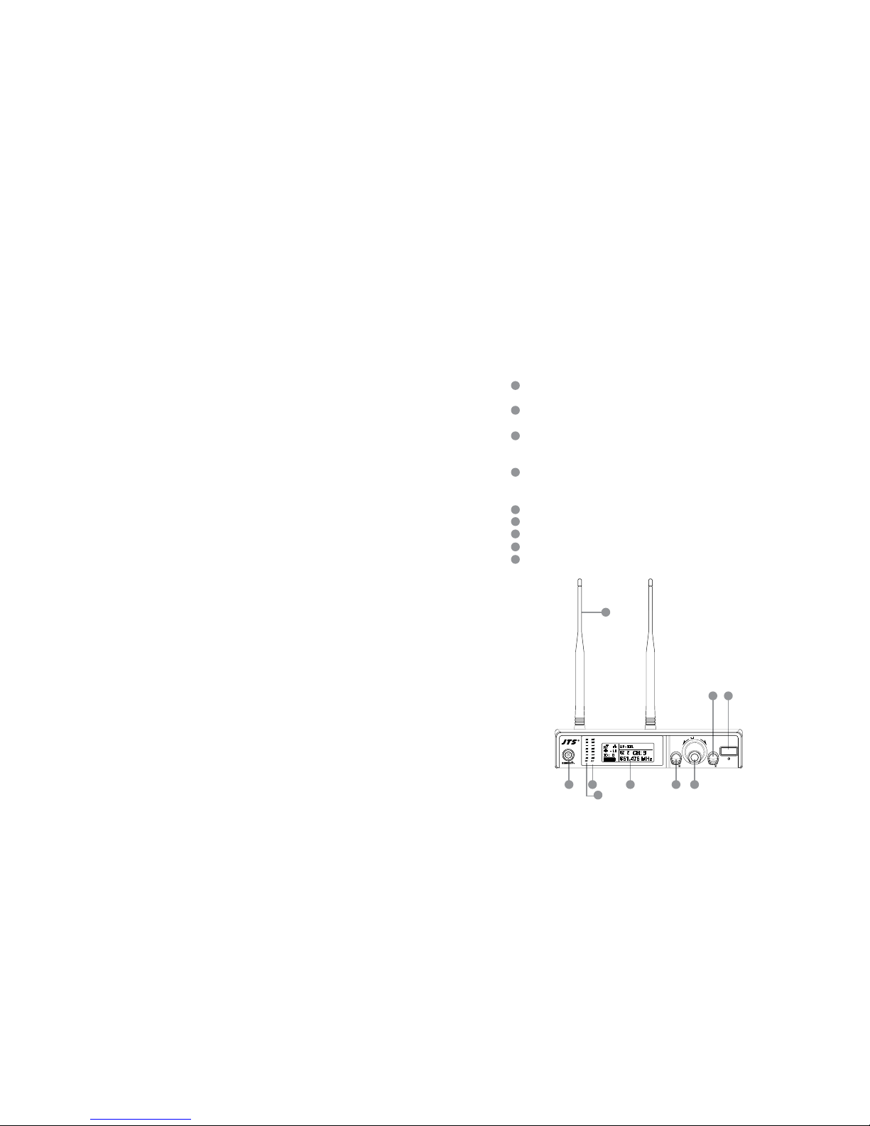
4-1 Broadband true diversity receiver key function and
LCD description//UF-10R
Power switch: press switch once to turn power on; press and hold for 2 seconds to shut
down.
EXIT key: when UF-10R is under “setup menu”, press EXIT to cancel selection or leave
menu.
Jog dial: when main menu is on screen, turn jog dial to adjust volume (MUTE,
-31~0dB); on “setup menu” screen, turn jog dial to select setup item, aer entering into the
selected item turn jog dial to adjust the value.
SETUP key: press and hold for 2 seconds to enter “setup menu”; press SETUP key to
enter into setup mode for jog dial; aer adjustment of value, press SETUP key to save the
seing.
REMOSET: Press REMOSET once to send frequency data to a microphone.
LCD: refer to “(2) Receiver LCD instruction”.
AF: indicate current audio signal strength.
RF: indicate current radio frequency signal strength.
Antenna: 1/2 wave length antenna.
1
4
7
2
5
8
3
6
9
12
3465 7
8
(1) Front panel
9
EXITSETUP
PUSH / CONTROL
UF-10R
wireless receiver
Professional Wideband (60~75MHz) True Diversity System
9
10
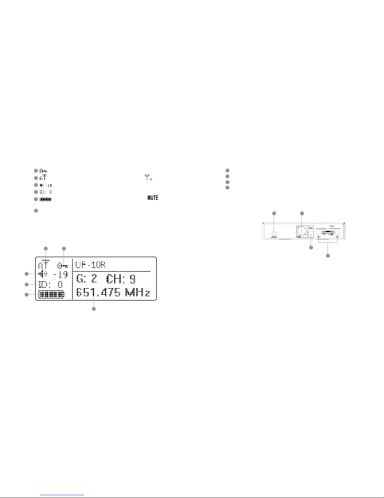
(2) Receiver LCD instruction
1011
12
13
14
15
15
11
12
13
14
10
: indicate key lock is set (Key lock on).
: show antenna A or B is receiving signal; signal is not received .
: indicate current receiver volume.
: indicate device ID seing: ID number 0~255.
: indicate transmier baery level; if no RF signal is received will show
up.
G: indicate current Group, 1~13
CH: indicate current Channel, CH1~63
Frequency indication: current operation frequency
(3) Rear panel
Power receptacle: connect to power supply (DC15V/1000mA)
Balanced XLR MIC output
φ 6.3mm balanced output
BNC antenna socket: ANT 1 and ANT 2, set antennas vertical or sloping for beer
reception.
18
17
16
19
16 17
18
19
CAUTION
Freq.Range:
1856
Made in Taiwan
Note: select MIC or LINE audio output dierence:
From setup menu, set “7. OUTPUT LEVEL”:
Set Line: Output level of XLR MIC output and Ø 6.3mm are identical
Set Mic: XLR MIC output level is lower than Ø 6.3mm output by “-20dB”

Professional Wideband (60~75MHz) True Diversity System
11
12
4-2 UHF PLL handheld transmitter key function and LCD description //
UF-10TH
LCD
Power key:
Turn on power: press power key once
Shut down power: press and hold power key for 2 seconds
Mute mode: during use, press power key once to mute the microphone, press it again to
release
, : up and down keys, select setup item
SET: set up and save data
Mute/REMOSET indicator lamp:
Mute mode: red light ashes
REMOSET successful: blue light on for 5 seconds
Baery compartment
20
21
22
23
24
25
20
25
21
22
22
23
24
For screen display and operation please refer to “6-2. System operation setup for
handheld transmier”.
4-3 UHF PLL Body-Pack Transmitter // UF-10TB
LCD
Baery
Low Baery Indicator: when baery lever is low this red LED will light on constantly.
Note: when switch on the unit the red LED will light on for 1 second and turn o.
AF Peak and Mute Indicator
AF PEAK : Orange
Mute mode: Red light ashes
Power Key
(1) Turn on power: press power key once
(2) Shut down power: press and hold Power Key for 2 seconds
(3) Mute mode: during use, press Power Key once to mute the microphone, press it
again to release.
(4) Leave the seing window: press the power key once the LCD display will return to
the main window.
, : up and down keys, select setup item
SET : set up and save data
User Name
Indicate current Group and current Channel
Current operation frequency
Baery status: display baery status
Microphone sensitivity
26
27
28
29
30
31
32
33
34
35
36
26
27 30
31
28
29
32
33
34
36
For screen display and operation please refer to “6-3. System operation setup for
Body-Pack transmier”.
 Loading...