

JTS UC-900RX Instruction Manual
59010-531-03
UC-900RX ACTIVE ANTENNA COMBINER
Operation
To enter the setting mode, press and hold the antenna setting key for 2 seconds until the input channel’s status
indicator
Selection Indicator
parameters in the third setting mode(RF Input), press the Antenna Setting Key
flashes. Use the Antenna setting key to cycle through the 3 settings menus as indicated by the Function
. Use the Up/Down keys to change the parameters in each settings mode. After setting your
a final time to save and exit the settings.
Parameter setting:
RF input attenuation
Press the up / down key
0dB: no attenuation
-31dB: attenuation of 31dB
to adjust the attenuation with interved of 1dB.
-10
Attenuation of 10dB
RF ATT
ANT Powering
RF Input
Antenna power supply
On: Provide + 12Vdc / 200mA to antenna inputs for active antenna or antenna booster.
OFF: OFF
ANT Powering
RF ATT
ANT Powering
RF Input
RF Input
En: Input Enable (Enable)
dis: input disabled (Disable); signal isolation: about 80dB
Default setting
1. Turn off the power
2. Press and hold the lock key
3. Turn on the power until the display show rSt
RF Input Enable
RF ATT
ANT Powering
RF Input
RF ATT
ANT Powering
RF Input
Precautions
•This product is used as the antenna integrator of the receiver, which is not recommended to be used with a transmitter.
• For the coaxial cable with antenna and UC-900RX, standard 50Ω coaxial cable must be used.
• When the antenna is connected to the unit with the coaxial cable, it is recommended to use Booster to compen sate for
cable loss or use 5D-FB coaxial cable.
• It is not advisable to place the antenna in the same space or where there are too much reflecting planes as they cause
multipath interference of the signal and affect the reception quality.
• When the antenna input signal is too large, it may cause distortion of the unit or receiver signal. If this is the case, try
adjusting the antenna input attenuation.
• When the power supply is abnormal, the panel light will flash and the machine will force to shut down all the corresponding
functions. Please turn off the power switch immediately.
Caution : To reduce the risk of fire or shock hazard, do not expose this appliance to heat or moisture.
Warning : To prevent electric shock, do not remove the cover. Refer all servicing to qualified service personnel or distributors.
1.
Read this instruction manual before using.
2. Keep this instruction manual.
3. Use the device in a well ventilated area. Do not block any ventilation openings.
4. Do not install the device near heat sources, Ex : Oven, furnaces or any other
apparatus that produce heat to prevent fire.
5. Do not place the device in humid or dusty environment to prevent short circuit.
6. Choose proper place to place the device to avoid product failure or personal
injury caused by accidental drops.
7. Do not use the device under lighting to avoid personal injury or equipment
damage caused by strikes.
8. Stop using and turn off the power when encounter abnormal situation. Contact
qualified service personnel or distributors.
> Machine has smoke or burning smell
> Water or any liquid has been spilled
9. Keep the machine outlet or plug clean. Dust gathering may result in bad
connection or electric fire.
10. Pay attention to the cable usage
> Hold the plug when unplugging. Breaking the wire may result in electric fire.
> Do not cut or twist the wire. Place the wire in a well ventilated area without
inflammable objects.
Instruction Manual
The UC-900RX is designed for receivers. It provides 2 x 4 antenna inputs to minimize RF dead zone on a stage or any
venue. It also feature RF input ON/OFF, input attenuation from -31 to 0 dB and input signal ON/OFF control. The
UC-900RX makes RF engineers’ job easy.
Accessories
• AC Power Cable x1
• BNC to BNC coaxial Cable x2
Operating Controls
UC-900RX
RX Antenna Combiner
4
Specifications
• Carrier Frequency Range: 470~960MHz
• Full System Gain: 3dB(±3dB)
• Input/Output Impedance: 50 Ω
• A/B Antenna Input:4+4
• OIP3: 35dBm(typ.) @ 2-tone;Pi=-15dBm/tone
• RF Input Attenuation: -31~0dB (Step:1dB)
• Input/Output Connectors: BNC(F):Input x8 / Output x2
• Functions:
1. Antenna Booster Powering ON/OFF Control
2. RF Input Attenuation Control
3. RF input Signal ON/OFF Control
• Antenna Booster Power: 12V/200mA*8
• Power Supply: 100~240VAC; MAX 2A 50/60Hz
• Dimension(mm): 480mm(W)*45mm(H)*260mm(D)
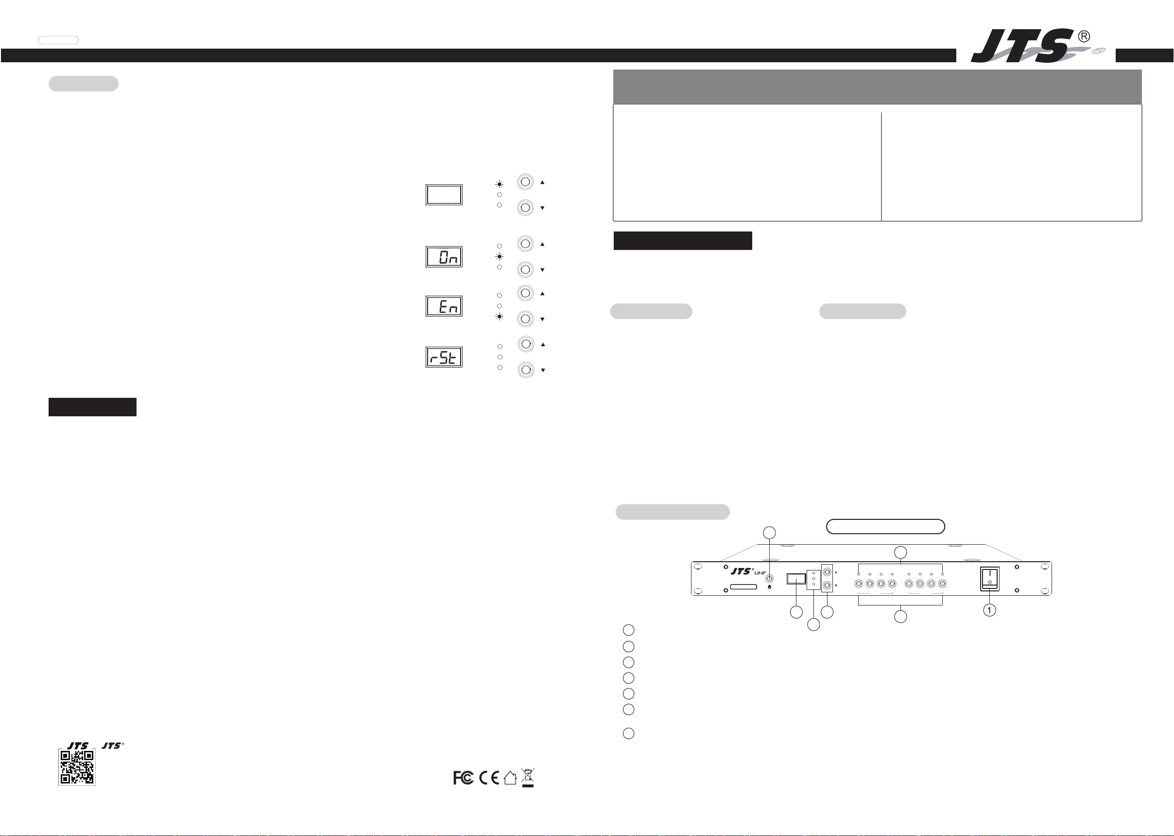
UC-900RX Front Panel
7
RF ATT
ANT Powering
RF Input
A1 A2 A3 A4 B1 B2 B3 B4
SET SET
PROFESSIONAL CO., LTD.
No. 148, 9th Industry Road, Ta-Li Industrial Park,
Taichung City, Taiwan, R.O.C.
Tel: 886-4-24938803 Fax: 886-4-24914890
E-mail: jts@jts.com.tw
www.jts.com.tw
35
1
Power switch
Antenna setting key: Select the CH to be set, press and hold for 2 seconds to enter the setting mode.
2
Up / Down key: In the setting mode, press the up / down key to select the parameter.
3
Key lock: long press 2 seconds to lock or unlock the panel key function.
4
3-digit seven-segment display: Displays the current setting.
5
Function selection indicator: In the setup mode, the indicator flashes in this order:
6
6
2
RF input attenuation, antenna Booster power on / off, RF input enable / disable.
7
Status indicator: Indicates the current antenna status,
a. Red: RF input enabled and antenna booster power on.
b. Green: RF input enabled and antenna booster power off.
c. Off: The antenna input is disabled.
d. All 8 channels flashing at the same time: Power supply is abnormal. Please shut down immediately.
14
11
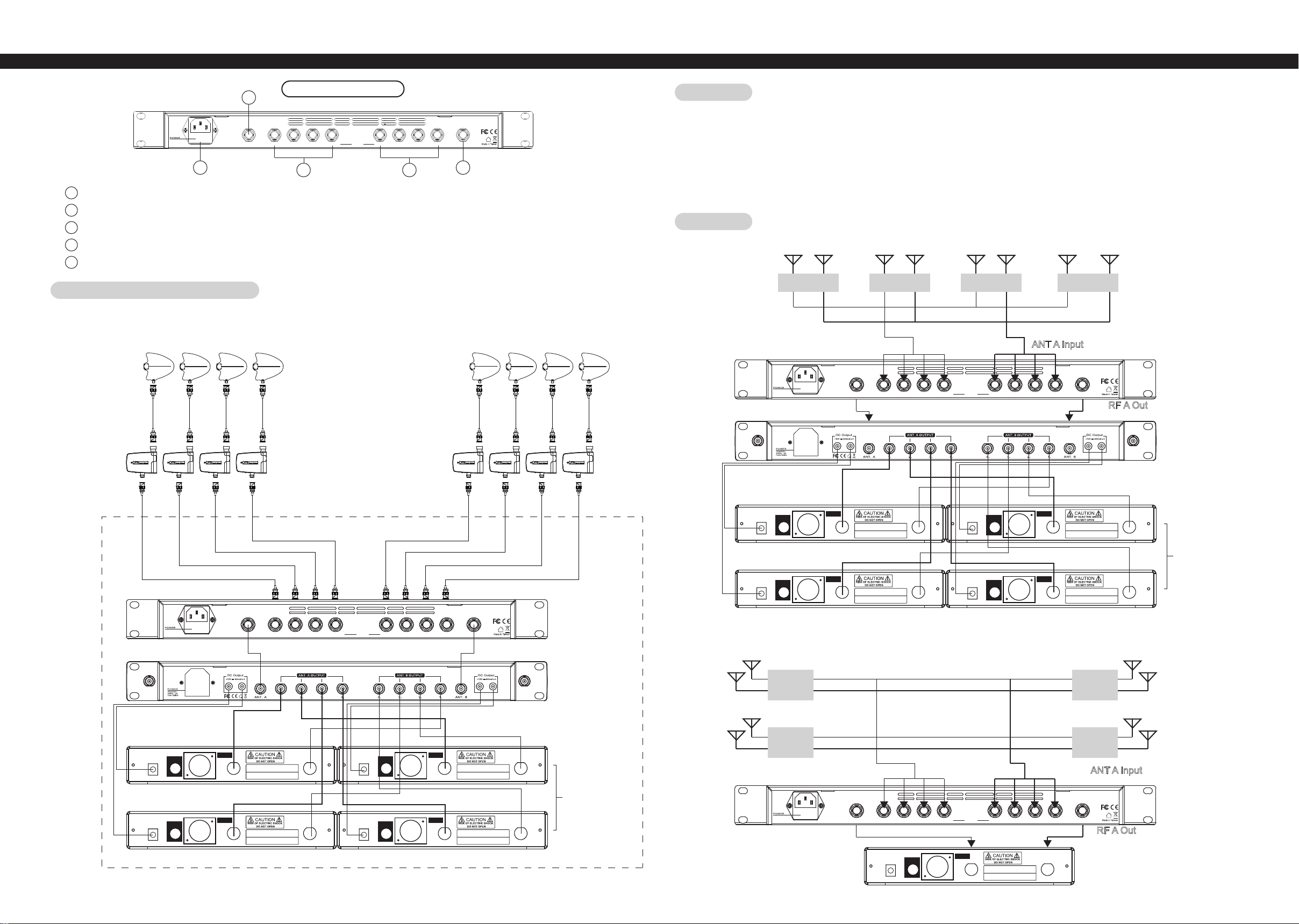
UC-900RX Rear Panel
100-240VAC~
50/60Hz, 2A
FUSE: T3.15A/250V
8 9
8
AC power supply: AC power input: 100 ~ 240VAC, MAX 2A, 50 / 60Hz.
9
Antenna A output
10
Antenna A inputs
11
Antenna B output
Antenna B inputs
12
RF OUT B RF OUT AB4 B3 B2 B1 A4 A2 A1A3
RF INPUT
12 10
Installation
• Connect the antenna through the coaxial cable to the antenna input. If the cable length is long, add the antenna booster or use
active antenna.
• Connect the antenna A / B output to the receiver or antenna distributor with coaxial cables.
• When the installation is complete, turn on the power. Depending on the situation, the user can set the relevant parameters
according to the operating instructions.
• When not in use, turn off the UC-900RX power.
Application
A1
EX 1.
B1 A2 B2 A3 B3 A4 B4
UC-900RX Antenna Configuration
UDA-49A
/ UDA-49P
UB-900i
DCV INPUT
12-18V/500mA
DCV INPUT
12-18V/500mA
STUDIO 1 STUDIO 2 STUDIO 3 STUDIO 4
100-240VAC~
50/60Hz, 2A
FUSE: T3.15A/250V
ANT B Input
RF OUT B RF OUT AB4 B3 B2 B1 A4 A2 A1A3RF INPUT
ANT A Input
RF B Out
AF OUTPUT
UNBAL .
AF OUTPUT
UNBAL .
AF OUTPUT
BALANCED
Freq. Range:
A1 B1 A2 B2
Serial No.:
AF OUTPUT
BALANCED
Freq. Range:
A3 B3 A4 B4
Serial No.:
ANT. 1ANT. 2
ANT. 1ANT. 2
DCV INPUT
12-18V/500mA
DCV INPUT
12-18V/500mA
AF OUTPUT
UNBAL .
AF OUTPUT
UNBAL .
AF OUTPUT
BALANCED
AF OUTPUT
BALANCED
Freq. Range:
Serial No.:
Freq. Range:
Serial No.:
UC-900RX
RF A Out
Antenna distributor
UA-948
ANT. 1ANT. 2
Receivers
ANT. 1ANT. 2
DCV INPUT
12-18V/500mA
DCV INPUT
12-18V/500mA
100-240VAC~
50/60Hz, 2A
FUSE: T3.15A/250V
AF OUTPUT
UNBAL .
AF OUTPUT
UNBAL .
RF OUT B RF OUT AB4 B3 B2 B1 A4 A2 A1A3RF INPUT
AF OUTPUT
BALANCED
Freq. Range:
A1 B1 A2 B2
Serial No.:
AF OUTPUT
BALANCED
Freq. Range:
A3 B3 A4 B4
Serial No.:
ANT. 1ANT. 2
ANT. 1ANT. 2
DCV INPUT
12-18V/500mA
DCV INPUT
12-18V/500mA
AF OUTPUT
UNBAL .
AF OUTPUT
UNBAL .
AF OUTPUT
BALANCED
AF OUTPUT
BALANCED
Freq. Range:
Serial No.:
Freq. Range:
Serial No.:
UC-900RX
EX 2.
A1
B1
Antenna distributor
UA-948
AREA 1
AREA 2
A3
B3
AREA 3
ANT. 1ANT. 2
ANT B Input
AREA 4
ANT A Input
Receivers
100-240VAC~
50/60Hz, 2A
FUSE: T3.15A/250V
RF OUT B RF OUT AB4 B3 B2 B1 A4 A2 A1A3RF INPUT
RF B Out
ANT. 1ANT. 2
AF OUTPUT
DCV INPUT
12-18V/500mA
AF OUTPUT
UNBAL .
BALANCED
Freq. Range:
A B
Serial No.:
ANT. 1ANT. 2
Receiver
A2
B2
A4
B3
UC-900RX
RF A Out
32
 Loading...