

JTS UC-900 Instruction Manual
THE UC-900 ACTIVE ANTENNA COMBINER
The UC-900 UHF antenna combiner actively combine antenna outputs from wireless transmitter such as SIEM-111T or
TG-10STX onto a single transmitting antenna,improving RF performance by reducing signal interference and saving further
antenna system investments. A wide-band operation frequency range from 470MHz - 970MHz. Equipped with 4 DC power
outlets that can be used for transmitters, without adding external power supplies.
Instruction Manual
Specifications
Accessories
Operating Controls
• AC Power Cable x 1
• DC Power Cable x 4
• BNC to BNC Cable x 4
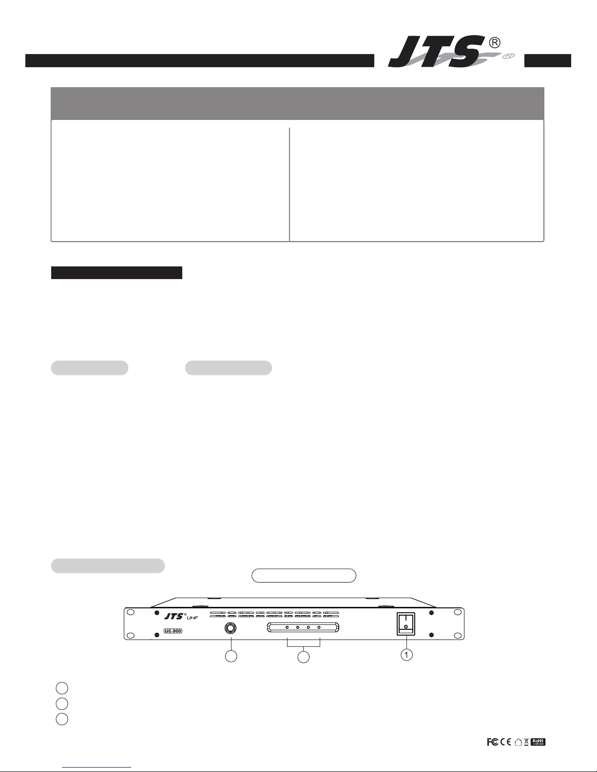
1 POWER SWITCH : The indicator will light up when power is on.
2 SIGNAL INDICATOR : When the input power signal is greater than +5dBm, the corresponding channel will light up.
3 BNC socket antenna output : Signal will be transmitted once combined.
Antenna Output CH1 CH2 CH3 CH4Antenna Combiner
UC-900 Front Panel
2
3
Caution : To reduce the risk of fire or shock hazard, do not expose this appliance to heat or moisture.
Warning : To prevent electric shock, do not remove the cover. Refer all servicing to qualified service personnel or distributors.
1.
Read this instruction manual before using.
2. Keep this instruction manual.
3. Use the device in a well ventilated area. Do not block any ventilation openings.
4. Do not install the device near heat sources, Ex : Oven, furnaces or any other
apparatus that produce heat to prevent fire.
5. Do not place the device in humid or dusty environment to prevent short circuit.
6. Choose proper place to place the device to avoid product failure or personal
injury caused by accidental drops.
7. Do not use the device under lighting to avoid personal injury or equipment
damage caused by strikes.
8. Stop using and turn off the power when encounter abnormal situation. Contact
qualified service personnel or distributors.
> Machine has smoke or burning smell
> Water or any liquid has been spilled
9. Keep the machine outlet or plug clean. Dust gathering may result in bad
connection or electric fire.
10. Pay attention to the cable usage
> Hold the plug when unplugging. Breaking the wire may result in electric fire.
> Do not cut or twist the wire. Place the wire in a well ventilated area without
inflammable objects.
• Frequency Range : 470 - 970MHz
• Input Connectors : Up to 4 transmitters
• Full System Gain : 0dB(±2dB)
• Maximum RF Input Power : +20dBm (100mW) /CH
• LED Indicator (Input signal Threshold) : >+5dBm (Threshold Power)
• Power Consumption : 6W
• Input / Output Connectors : BNC@50Ω : 4 Antenna Input at back, 1 Antenna Output at front.
DC Output Jacks : 4 at back.
• DC Output : DC12V/1A Max (4 outputs, total of 48W)
• Input Voltage : 100-240 VAC, 50/602Hz, MAX 2A
• Dimensions (m/m) : W480 * H45 * D260 mm
• Weight : 2.3kg
Note
Installation and Operation
• UC-900 provides 4 RF input with operation frequency range of 470~970MHz. For optimum performance, please use same frequency
range for all transmitters. ( UDA-49P directional antenna not restricted. )
• Please use standard 50Ω BNC cable when connecting to the UC-900.
• Turn off the power of transmitters and UC-900 before installing or disconnecting.
59010-512-01
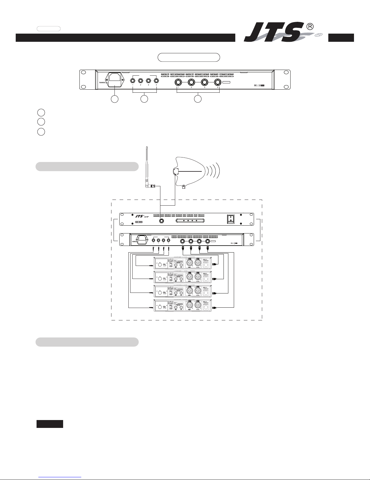
UC-900 Antenna Configuration
DC Output
12Vx4A(MAX)
RF Input
DC Output
12Vx4A(MAX)
100-240V
50/60Hz
FUSE: T3.15A/250V
4 BNC socket antenna input : Can be connected to 4 transmitters. For best performance, please do not input more than +20dBm.
5 DC output jacks : Provides DC 12V at max. 1A from each jack. (Total of 48W)
6 AC power input : Power input 100~140VAC / 2A Max, 50/60Hz.
UC-900 Rear Panel
6
5 4
• Use 1/2 wave antenna or UDA-49P directional antenna to connect to the UC-900 Antenna Output. To avoid losing of transmitting
output power, if possible, please use shortest BNC –BNC cable when connect UDA-49P directional antenna to the UC-900
Antenna Output.
• Use the supplied BNC-BNC cables to connect the antenna outputs of each transmitter to the antenna inputs of the antenna combiner.
• If needed, connect the DC OUTPUT of combiner to the DC INPUT of each transmitter.
• Turn on the power and setup the frequencies of all transmitters. (All transmitters must be in the same frequency range.)
• Please turn off the power when not use or before disconnecting the cables or antenna.
Wireless Transmitter
UDA-49P
UC-900 Front Panel
UC-900 Rear Panel
DC Output
12Vx4A(MAX)
RF Input
DC Output
12Vx4A(MAX)
100-240V
50/60Hz
FUSE: T3.15A/250V
Antenna Output CH1 CH2 CH3 CH4Antenna Combiner
OR
1/2 wave antenna
 Loading...